2000 HONDA CR-V key ignition switch
[x] Cancel search: key ignition switchPage 56 of 1395
Starting System
Starter Test (cont'dl
Check lor Wear and D8mage
The starter should crank the engine smoothly and
steadily. lf the staner engages, but cranks the engine
erratically, remove it, and inspect the starter drive gear
and torque converter ring gear or flywheel ring gear for
oamage.
Check the drive gear overrunning clutch for binding or
slipping when the armature is rotated with the drive
gear held. lf damaged, replace the gears.
Check Cranking Voltage and Current Draw
Cranking voltage should be no less than 8.7 volts on Ay'T
models, and 8.0 volts on M/T moders.
Current draw should be no more than 230 amperes on
A,/T models, and 200 amperes on M/T models.
lf cranking voltage is too low, or current draw too high,
check for:
. dead or low battery.
a open circuit in starter armature commutator seg,
ments.
. starter armature dragging.
. shorted armature winding.
. excessive drag in engine.
Check Cranking rpm
Engine speed during cranking should be above 100 rpm.
lf speed is too low, check for:
a loose baftery or starter terminals.
. excesslvely worn staner brushes
. open circuit in commutator segments.
. dirty or damaged helical splines or drive gear.
a defective drive gear overrunning clutch.
Check Starter Disengagement
With the shift lever in @ or @ position (A,iT) or with the
clutch pedal depressed {M/T). turn the ignition switch to
START (lll). and release to ON (ll).
The starter drive gear should disengage from the torque
converter ring gear or flywheel ring gear when you
release the key.
lf the drive gear hangs up on the torque converter ring
gear or flywheel ring gear, check for
. solenoid plunger and switch malfunction.
. dirty drive gear assembly or damaged overrunning
clutch.
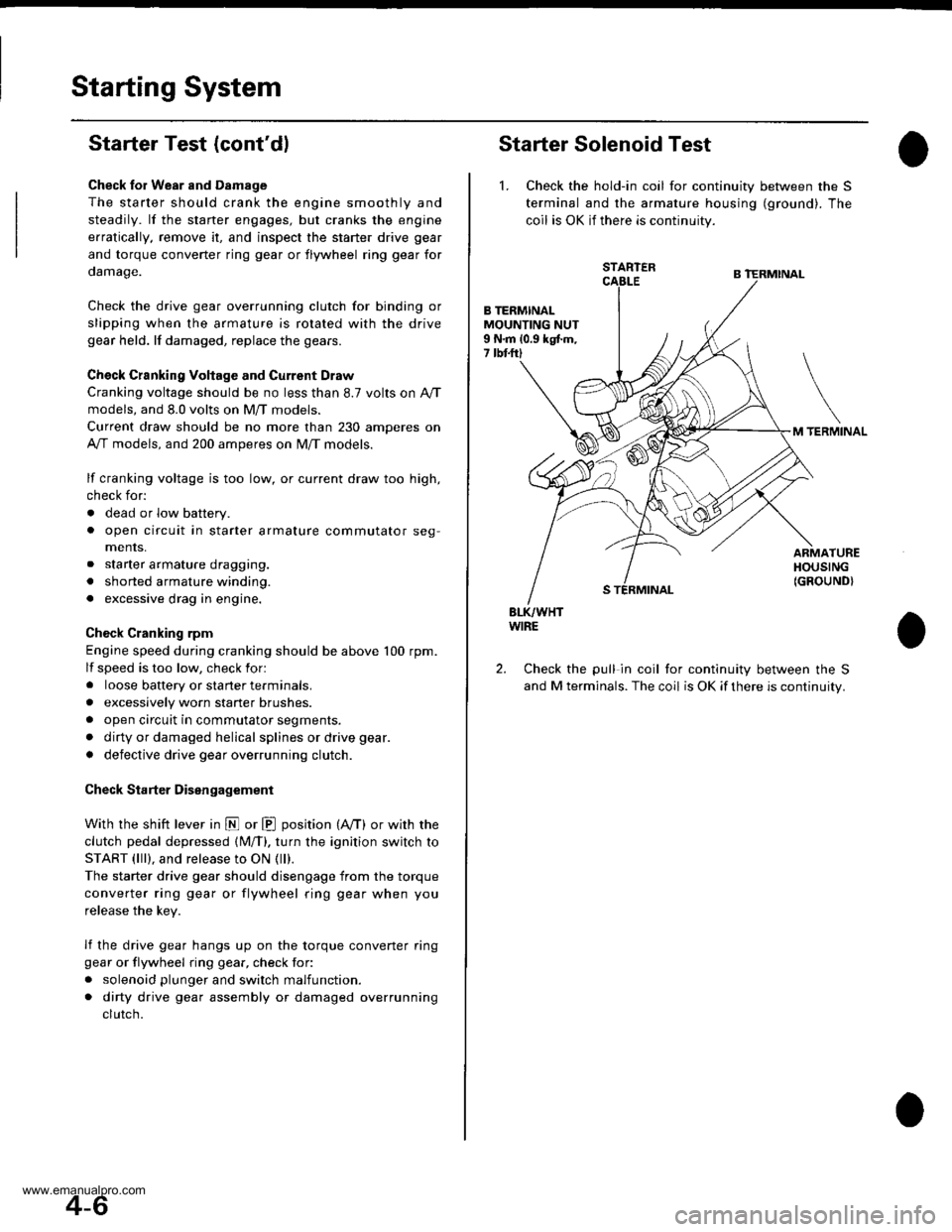
Starter Solenoid Test
1. Check the hold-in coil for continuity between the S
terminal and lhe armature housing (ground). The
coil is OK if there is continuity.
STARTER
B TERMINALMOUNTING NUT9 N.m 10.9 kgtm,7 tbtftl
TERMINAL
ARMATUREHOUSING(GROUND}
BLK/WHTWIRE
Check the pull in coil for continuity between the S
and M terminals. The coil is OK if there is continuity.
2.
4-6
www.emanualpro.com
Page 577 of 1395
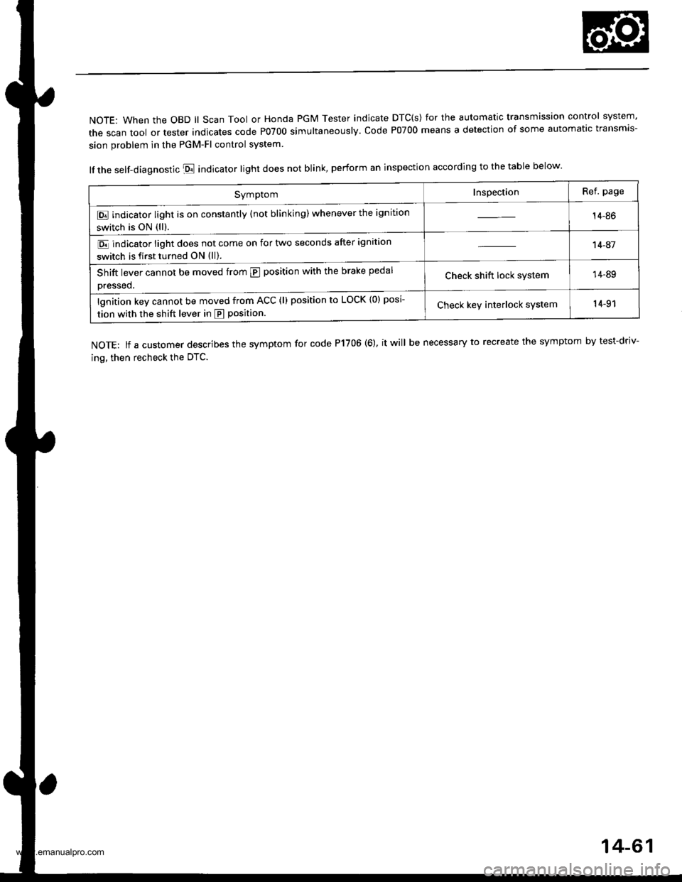
NOTE: When the OBD ll Scan Tool or Honda PGM Tester indicate DTC(s) for the automatic transmission control system'
the scan tool or tester indicates code P0700 simultaneously. code P07oo means a detection of some automatic transmis-
sion problem in the PGM-Fl control system
lf the self-diagnostic E indicator light does not blink, perform an inspection according to the table below.
NOTE: lf a customer describes the symptom for code P1706 (6), it will be necessary to recreate the symptom by test-driv-
ing, then recheck the OTC.
SymptomInspectionRef. page
E indicator light is on constantly (not blinking) whenever the ignition
switch is ON (ll).14-86
E indicator light does not come on for two seconds after ignition
switch is first turned ON (ll).
't 4-41
Shift lever cannot be moved from @ position with the brake pedal
Dressed,Check shift lock system14-89
lgnition key cannot be moved from ACC (l) position to LOCK {0) posi
tion with the shift lever in E position.Check keY interlock system14-91
14-61
www.emanualpro.com
Page 579 of 1395
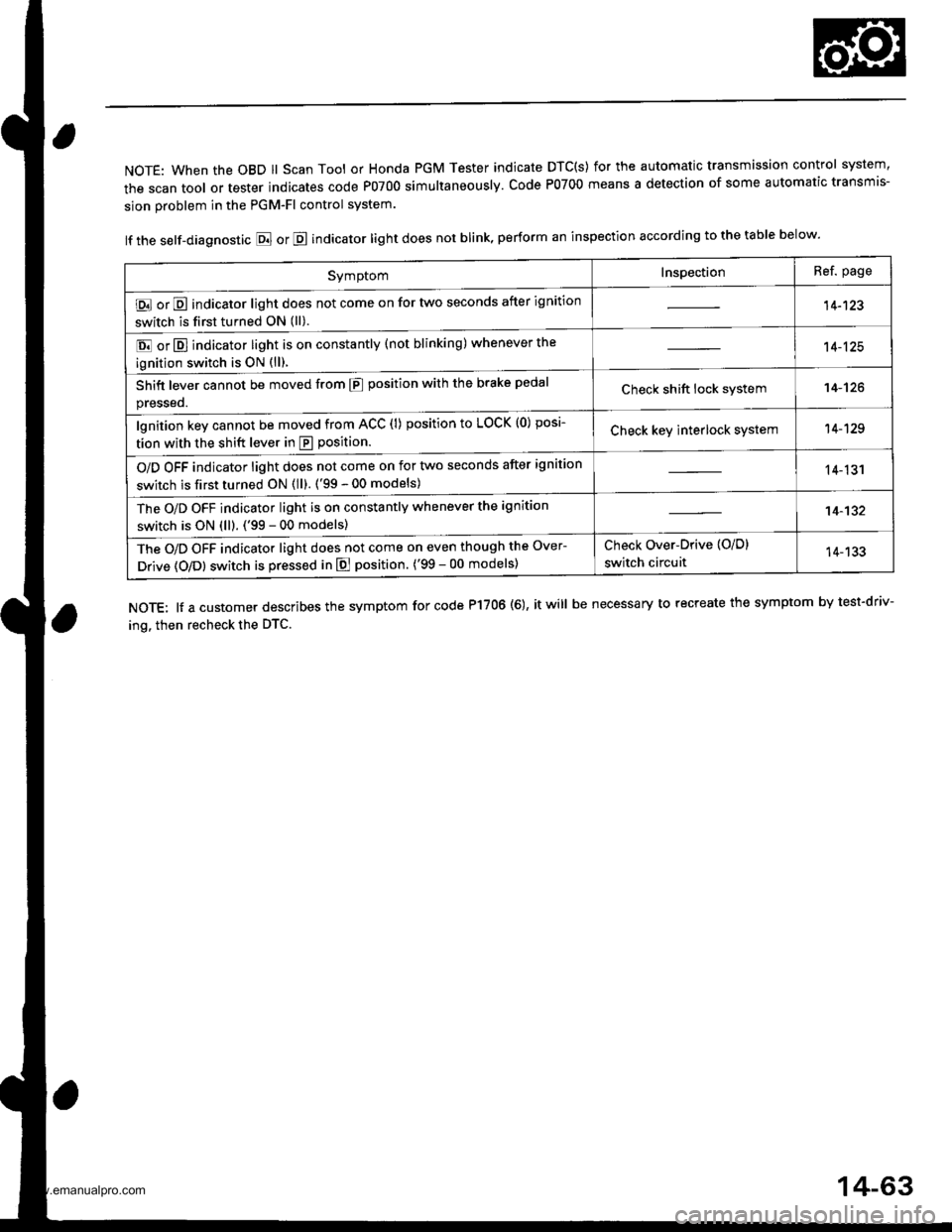
NOTE: When the OBD ll Scan Tool or Honda PGM Tester indicate DTC(S) for the automatic transmission control system,
the scan tool or tester indicates code P0700 simultaneously. Code P0700 means a detection of some automatic transmis-
sion problem in the PGM-Fl control system.
lf the self-diagnostic E or E indicator light does not blink, perform an inspection according to the table below.
NOTE: lf a customer describes the symptom for code P17OO (6), it will be necessary to recreate the symptom by test-driv-
ing. then recheck the DTC.
SymptomInspectionRef. page
E or E indicator light does not come on for two seconds after ignition
switch is first turned ON (ll).14-123
E or E] indicator light is on constantly (not blinking) whenever the
ignition switch is oN {ll).
14-125
Shift lever cannot be moved from E position with the brake pedal
presseo.Check shift lock system14-'t26
lgnition key cannot be moved from ACC (l) position to LOCK (0) posi-
tion with the shift lever in E position.Check key interlock system14-129
O/D OFF indicator light does not come on for two seconds after ignition
switch is first turned ON (ll). ('99 - 00 models)14-131
The O/D OFF indicator light is on constantly whenever the ignition
switch is ON (ll). ('99 - 00 models)14-132
The O/D OFF indicator light does not come on even though the Over-
Drive (O/Dl switch is pressed in E position. ('99 - 00 models)
Check Over-Drive {O/D}
switch circuit14-133
14-63
www.emanualpro.com
Page 607 of 1395
![HONDA CR-V 2000 RD1-RD3 / 1.G Workshop Manual
Troubleshooting Flowchart - Interlock system - Key Interlock system
IGNITION SW]TCH 6P CONNECTOR
KEY LOCK SOL
{WHT/BLU)
ACC PUSH SW (WHT/YELI
Wire side oI female terminals
KEY LOCK SOL(WHT/BLUI
(cont HONDA CR-V 2000 RD1-RD3 / 1.G Workshop Manual
Troubleshooting Flowchart - Interlock system - Key Interlock system
IGNITION SW]TCH 6P CONNECTOR
KEY LOCK SOL
{WHT/BLU)
ACC PUSH SW (WHT/YELI
Wire side oI female terminals
KEY LOCK SOL(WHT/BLUI
(cont](/manual-img/13/5778/w960_5778-606.png)
Troubleshooting Flowchart - Interlock system - Key Interlock system
IGNITION SW]TCH 6P CONNECTOR
KEY LOCK SOL
{WHT/BLU)
ACC PUSH SW (WHT/YELI
Wire side oI female terminals
KEY LOCK SOL(WHT/BLUI
(cont'd)
lgnition key cannot be moved
Irom ACC (l) pGition to LOCK (0)
position while Pushing the igni-
tion kev with the shift lever in lllposifio;, and the shift lever but-
ton rcleased.
Check Key Interlock Solenoid
Op€ration:1. Disconnect the ignition switch
connector (6P).
2. Connect the No. 4 terminal of
the ignition switch 6P connec-
tor to the battery Positive ter
minal, and connect the No. 3
terminal to the battery nega
tive terminal.3. Check the key interlock sole
noid operation A clicking
so!nd sho!ld be heard.
Faulty koy interlock solenoid.
Replace the ignition key cylinder/
steedng lock as36mbly
Does the key interlock
solenoid operate properly?
Check Key Interlock Switch OPer'
adon:1. Connect the No. 5 terminal of
the ignition switch connector
to the battery Positive termi
nal, and connect the No 3 ter
minal to the baftery negative
termrnal,2. Turn the ignition switch to
ACC (l), then push rt.
3. Check the key interlock sole'
noid operation. A clicking
sound should be heard whilepushing the ignition key.
Faulty key inte.lock switch
Replaco the ignition key cylindor/
stoering lock a3r.mblY.
Does the key interlocksolenoid operate ProPerlY?
To page 14 92
14-91
www.emanualpro.com
Page 608 of 1395
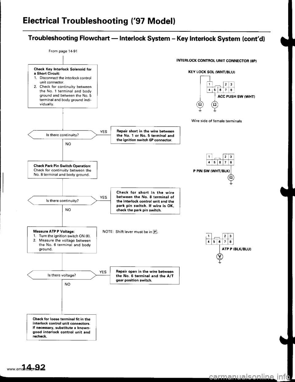
Electrical Troubleshooting {'97 Model)
Troubleshooting Flowchart - Interlock System - Key Interlock System lcont'dl
INTERLOCK CONTROL UNIT CONNECIOR {8PI
KEY LOCK SOL {WHT/8I-UI
ACC PUSH SW IWHTI
Wire side of female terminals
ATP P (BLK/BLU)
Check Key Interlock Solenoid fora Short Circuit:1. Disconnect the interlock controlunit connector.2. Check for continuity betweenthe No. l terminal and bodyground and between the No.5terminaland body ground indi-vidually.
Repair short in the wire betweenthe No. 1 or No. 5 terminal andthe ignition switch 6P connector.
ls there continuity?
Check Park Pin Switch ODeration:Check for continuity between theNo. I terminal and body ground.
Check tor shori in the wirebetwo€n the No. 8 terminal otthe interlock control unit and thepark pin switch. lf wire is OK,ch6ck the park pin switch.
ls there continuity?
Measu16 ATP P Voltage:1. Turn the ignition switch ON lll).2. Measure the vohage betweenthe No.6 terminal and bodyground.
R6pei. open in the wire betweenthe No. 6 i€rminal and the A/Tgea. position switch.
Check for loose terminalfit in theinterlock control unil connectors.lf necessery, substitute a known-good interlock control unit andr6check.
From page 14-91
Shift lever must be in E.
14-92
www.emanualpro.com
Page 645 of 1395
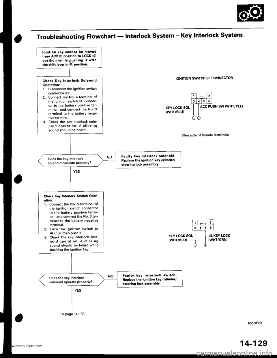
Troubleshooting Flowchart - Interlock system - Key Interlock system
IGNITION SWITCH 6P CONNECTOR
KEY LOCK SOL
IWHT/BLU)
ACC PUSH SW (WHT/YEL}
Wire side ot female terminals
KEY LOCK SOL
IWHT/BLUI
+B KEY LOCK(WHT/GRN)
(cont'd)
lgnition ksy cannot be moved
from ACC (l) pGition to LOCK (01
position while Pushing it with
the shift lever in E PGition.
Check Key lntorlock Solenoid
Operation:1. Disconnect the ignition switch
connector (6P).
2. Connect the No. 4 terminal of
the ignition switch 6P connec-tor to the battery Posative ter_minal, and connect the No. 3
terminal to the battery nega
tive terminal.3. Check the key interlock sole-no id operation. A clicking
sound should be heard.
F.ulty key interlock solenoid.
Replace tho ignition key cylinder/
steering lock asembly.
Does the key interlocksolenoid operate ProPerlY?
Ch€ck Key |motlock Switch OPer'etion:1. Connect the No. 5 terminal of
th€ ignition switch connectorto the battery Positive termi-nal, and connectthe No.3 teF
minal to the baftery negativetermrnal,2. TLrrn the ignition switch toACC (l), then PUsh it.3. Check the key interlock sole-noid operation. A clickingsound should be heard whilepushing the ignition kev.
Faulty key interlock 3witch.
Roplaco the ignidon key cylinder/
steoring lock tssamblY.
Does the key interlocksolenoid operate Properly?
To page 14-130
14-129
www.emanualpro.com
Page 646 of 1395
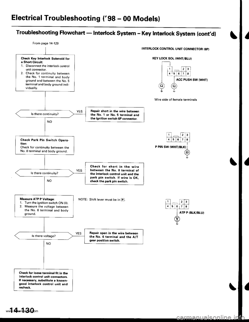
Electrical Troubleshooting ('98 - 00 Models)
Troubleshooting Flowchart - Interlock System - Key Interlock System (cont,dl
INTERLOCK CONTROL UNIT CONNECTOR {8PI
KEY LOCK SOL (WHT/BI-U}
ACC PUSH SW {WHT)
Wire side of female terminals
ATP P IBLK/BLUI
From page 14'129
Shift lever must be in E.
Check Key Intorlock Solonoid tola Short Circuit:1. Disconnect the interlock controlunit connector,2. Check for continuity betweenthe No. l terminal and bodyground and between the No.5terminal and body ground individually.
Repair shon in thc wire betweonthe No. 1 or No. 5 terminal andth€ ignhion switch 6P connector.
ls there continuity?
Check Park Pin Switch Opera-tion:Check for continuity between theNo. I terminal and body ground.
Check for short in the wir6between the No. 8 terminal ofthe int€rlock control unit and thopark pin switch. ll wire is OK,ch6ck the park pin switch.
ls there continujty?
Moasure ATP P Voftegel1. Turn the ignition switch ON (lli.2. Measure the voltage betweenthe No. 6 terminal and bodyground.
Repair open in the wiro betweenthe No. 6 termin.l and the A/Tgear position 3witch.
Check for looseterminal fit in th€interlock control unit connoctors.lf necosssry, substitute t known-good interlock control unit andrecheck.
14-130
www.emanualpro.com
Page 661 of 1395
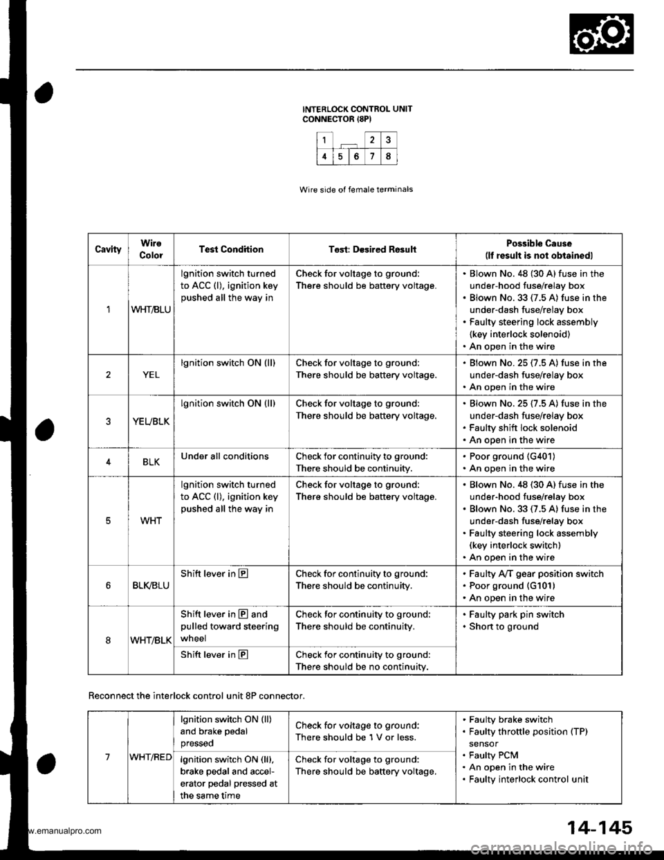
1?
4678
CavityWire
ColorTest CondhionTost: Desired RosultPossible Cause(lf result is not obtainedl
1WHT/BLU
lgnition switch turned
to ACC (l), ignition key
pushed all the way in
Check for voltage to ground:
There should be battery voltage.
Blown No. 48 {30 A} fuse in the
under-hood fuse/relay box
Blown No.33 (7.5 A) fuse in the
under-dash fuse/relay box
Faulty steering lock assembly
{key interlock solenoid)
An open in the wire
YEL
lgnition switch ON (ll)Check for voltage to ground:
There should be battery voltage.
Blown No.25 (7.5 A) fuse in the
under-dash fuse/relay box
An open in the wire
YEUBLK
lgnition switch ON (ll)Check for voltage to ground:
There should be baftery voltage.
Blown No. 25 (7.5 A) fuse in the
under-dash fuse/relay box
Faulty shift lock solenoid
An open in the wire
4BLKUnder all conditionsCheck for continuity to ground:
There should be continuity.
. Poor ground (G401)
. An open in the wire
5WHT
lgnition switch turned
to ACC (l), ignition key
pushed all the way in
Check for voltage to ground:
There should be battery voltage.
Blown No.48 (30 A) fuse in the
under-hood fuse/relay box
Blown No. 33 (7.5 A) fuse in the
under-dash fuse/relay box
Faulty steering lock assembly(key interlock switch)
An open in the wire
BLI(BLU
Shift lever in ECheck for continuity to ground:
There should be continuity,
Faulty Ay'T gear position switch
Poor ground (G101)
An open in the wire
8WHT/BLK
Shift lever in @ and
pulled toward steering
wneel
Check for continuity to ground:
There should be continuity.
Faulty park pin switch
Shon to ground
Shift lever in ECheck for continuity to ground:
There should be no continuity.
Wire side of female terminals
Reconnect the interlock control unit 8P connector.
14-145
7WHT/RED
lgnition switch ON (ll)
and brake pedal
presseo
Check for voltage to ground:
There should be 1 V or less.
Faulty brake switch
Faulty throttle position (TP)
sensor
Faulty PCM
An open in the wire
Faulty interlock control unit
lgnition switch ON (lll,
brake pedal and accel-
erator pedal pressed at
the same time
Check for voltage to ground:
There should be baftery voltage,
www.emanualpro.com