Page 1206 of 1395

Ground Distribution
Ground-to-Component(sl Index
GroundWire Color
G2
G3
G 10'l
G201
G202
G351
BLIVRED
BRN
BLK
BLK
BRN/BLK
BLK
BLK
BLK
23-46
Component or Circuits Grounded
Battery
Valve Cover
Transmission housing
A,/T gear position switch
ECM (PG1, PG2) ('98 - 00 models: M/T)
PCM (PG1, PG2l (Avrr)
PGM-FI main relay
Power steering pressure (PSP) switch
Radiator fan switch
VSS
Data link connector
ECM (1G1, LG2) ('98 - 00 models: M/T)
PCM (LGI, LG2) (IVT)
Shielding:
between ECM ('98 - 00 models: M/T) or PCM (Ay'T) and CKF sensorbetween ECM {'98 - 00 modets: M/T} or pCM (Ay'T) and CKp sensorbetween ECM ('98 - 00 models: M/T) or PCM (rVT) and CYP sensorbetween ECM ('98 - 00 models: M/T) or PCM (Ay'T) and TDC sensorbetween ECM {'98 - 00 models: M/T) or PCM (ly'T) and countershaft speed sensor (Ay'T)
between ECM ('98 - 00 models: M/T) or PCM {A,,/T) and mainshaft sp€ed sensor {!VT)between ECM ('98 - 00 models: M/T) or PCM (A,/T) and primary HO2Sbetween ECM ('98 - 00 models: M/T) or PCM (Ay'T) and secondary HO2SHorn (High)
Horn {Low}
Radiator fan motor
Right headlight
Right front parking light
Right front side marker light
Right front turn signal light
Condenser fan motor
Cruise actuator
Left front parking light
Left front side marker light
Left front turn signal light
Left headlight
Rear window washer motor
Windshield washer motor
ABS pump motor
www.emanualpro.com
Page 1214 of 1395

lgnition Switch
Test
SRS components are located in this area. Review the
SRS component locations, precautions, and procedures
in the SRS section {24} before performing repairs or ser
vtce.
L lMake sure you have the anti-theft code for the
radio, then write down the frequencies for theradio's preset buttons (wilh anti-theft feature).
2. Disconnect the battery negative cable.
3. Remove the driver's dashboard lower cover and the
knee bolster {see section 20).
4. Disconnect the 5P connector from the under-dash
fuse/relay box and the 3P connector from the main
wtre narness,
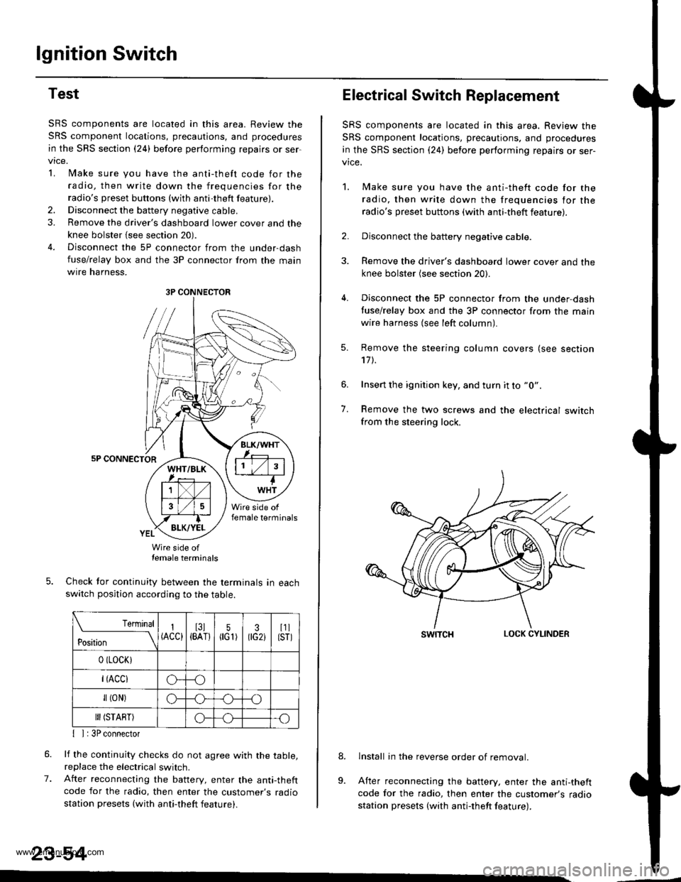
5P CONNECTOR
Wire side oftemale terminals
Check tor continuity between the terminals in eachswitch position according to the table.
rernrnal
ros[ron \
I(ACC)I3l{BAT}5flG1)30G2iI1llsrl
0 (LocK)
r(Acclo--o
fl (oN)G_o
III (START)o--.o
7.
{ I | 3P connector
lf the continuity checks do not agree with the table,replace the electrical switch.
After reconnecting the battery, enter the anti-theftcode for the radio, then enter the customer's radio
station presets (with anti-theft feature).
23-54
3P CONNECTOR
Electrical Switch Replacement
SRS components are located in this area. Review the
SRS component locations, precautions, and procedures
in the SRS section {24) before performing repairs or ser-vice.
1. Make sure you have the anti-thett code for the
radio, then write down the frequencies for the
radio's preset buttons (with anti-theft feature).
2. Disconnect the battery negative cable.
3. Remove the driver's dashboard lower cover and the
knee bolster (see section 20).
4. Disconnect the 5P connector from the under,dash
tuse/relay box and the 3P connector f.om the main
wire harness {see left column).
7.
Remove the steering column covers (see section'17 t.
Insert the ignition key, and turn it to "0".
Remove the two screws and the electrical switchfrom the steering lock,
swrTcHLOCK CYLINDER
lnstall in the reverse order of removal.
After reconnecting the battery, enter the anti-theftcode for the radio, then enter the customer's radiostation presets (with antj-theft feature).
9.
www.emanualpro.com
Page 1221 of 1395
Removal
'1. Remove the two screws from the instrument panel.
2. Remove the instrument panel carefully to avoid damaging the clips.
3. Tilt the steering wheel down with the tilt adjustment lever.
4, Spread a protective cloth over the steering column.
5. Remove the four mounting screws from the gauge assembly.
6. Pullthe gauge assembly out, and disconnect all connectors from it.
7, Remove the gauge assembly.
GAUGE ASSEMELY
INSTRUMENT PANEL
23-61
www.emanualpro.com
Page 1238 of 1395
Lighting System
Combination Light Switch Test
'1. Remove the driver's dashboard lower cover and the knee bolster (see section 20).
2. Remove the steering column covers (see section '17).
3. Disconnect the 4P and 7P connector from the switch.
4. Remove the screws, and slide the switch toward the driver,s door,
5. Inspect the connector and socket terminals to be sure they are all making good contact.
r : Canada
23-78
4P CONNECTOR
23I
56
Position
Terminal12356
Headlight switch
OFF
:m:o_----o
=DL0wo------oo-----o
HIGHo_----oo-_--_o_----o
Passing switchOFF
ONo_---o
www.emanualpro.com
Page 1247 of 1395
Turn Signal Switch Test
1.
4.
Remove the driver's dashboard lower cover and the
knee bolster (see section 20).
Remove the steering column covers {see section
17]-.
Disconnect the 4P and 7P connectors from the
switch.
Remove the screws, and slide the switch toward the
driver's door.
Check for continuity between the terminals in each
switch position according to the table.
Position
Terminal12
RIGHTo-
Neutral
LEFTo---o
q
tl-
swtTcH
Hazard Warning Switch Test
1. Remove the center panel {see section 20).
2. Remove the two screws, then remove the switch
from the center air vent.
HAZARD
Check for continuitv between the terminals in each
switch position according to the table.
Terminal
t**--\
2357810
OFF(9U(_)
ONo@oooo
lNol us€d)
23-87
www.emanualpro.com
Page 1266 of 1395

Horns
Switch Test
Disconnect the battery negative cable, then disconnect
the positive cable, and wait at ieastthree minutes.
Disconnect the driver's airbag and front passenger's
airbag connectors (see section 24).
Remove the drive.'s dashboard lower cover and the
knee bolster (see section 20).
Disconnect the cable reel sub-harness 3P or 6P con-
nector from the main wire harness.
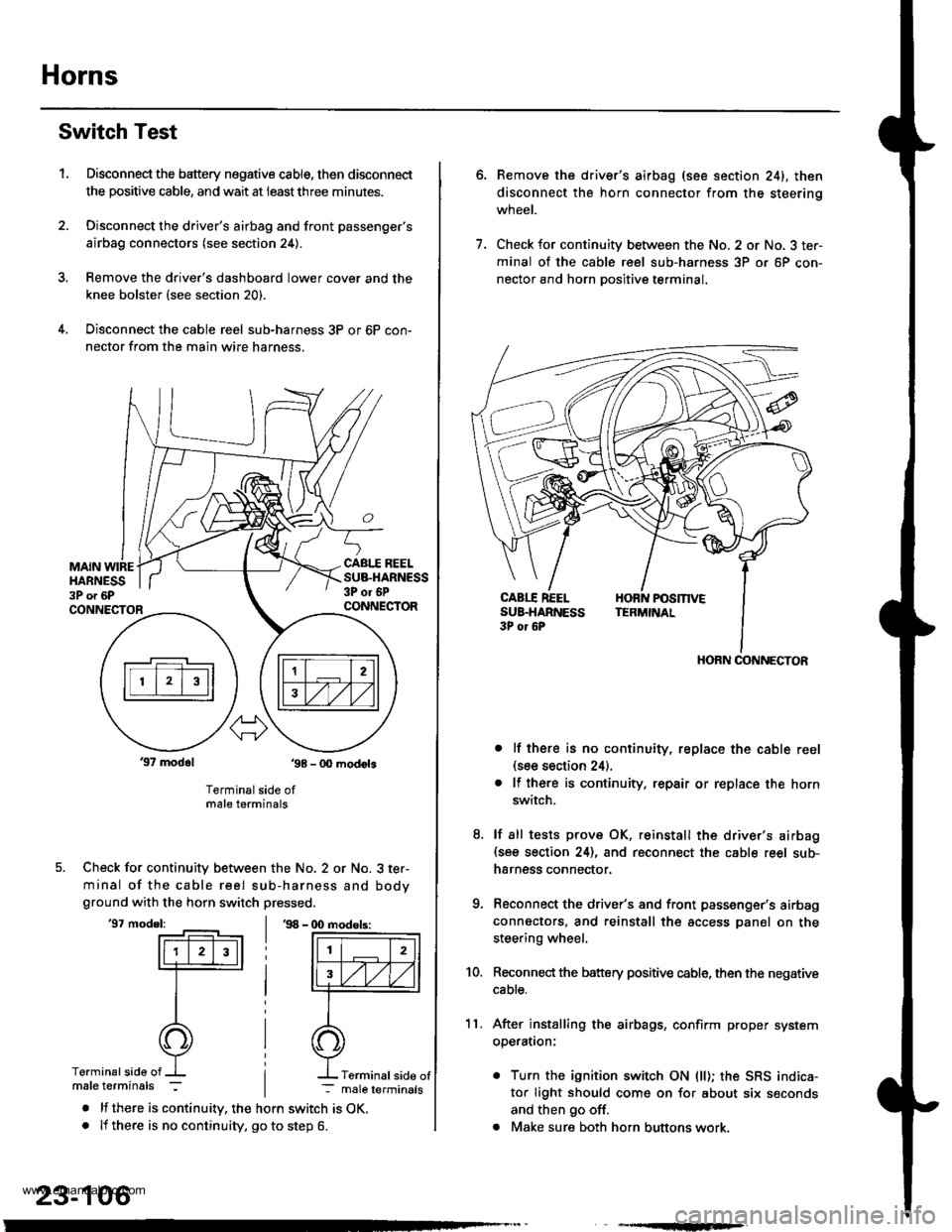
1.
MAIN WIREHARNESS3P o. 6P
CABI.I REELSUB.HARNESS3P or 6PCONNECTORCONNECTOR
37 modol ,98 - 0O modots
Terminal side ofmale terminals
Check for continuity between the No. 2 or No. 3 ter-
minal of the cable reel sub-harness and bodyground with the horn switch pressed.
'97 model:'98 - (X) modols:
Terminalside of
. lf there is continuity. the horn switch is OK.. lf there is no continuity, go to step 6.
23-106
Terminal side of
6.Remove the driver's airbag (see section 241, then
disconnect the horn connector from the steerinq
wneet.
Check for continuity between the No. 2 or No. 3 ter-
minal of the cable reel sub-harness 3P or 6P con-
nector and horn Dositive terminal.
lf there is no continuity, replace the cable reel(see section 24).
lf there is continuity. repair or replace the horn
switch.
lf sll tests prove OK, reinstall the driver's airbag(see section 24), and reconnect the cable reel sub-
harness connector.
Reconnect the driver's and front passenger's airbag
connectors, and reinstall the access panel on the
steering wheel.
Reconnect the battery positive cable, then the negative
cable.
After installing the airbags, confirm proper system
operatron:
. Turn the ignition switch ON (ll); the SRS indica-
tor light should come on for about six seconds
and then go off.
. Make sure both horn buttons work.
7.
11.
8.
9.
10.
HORN CONNECTOR
www.emanualpro.com
Page 1279 of 1395

Wiper/Washer Switch Test
Windshield/ReEr Window Wiper/Washer Switch:
1. Remove the driver's dashboard lower cover and the
knee bolster (see section 20).
2. Remove the steering column covers {see section 17)
3. Disconnect the 8P and 6P connectors from the
switch, remove the two screws, and pull out the
switch.
J-
lind3hi.ld:
tilt-rltl
IEZIA
Raar Window:
11 2 3
I t-7 al
ll -
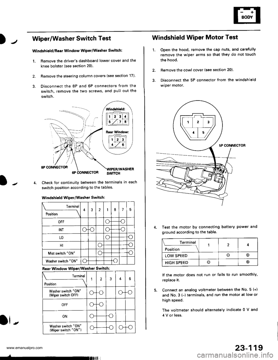
Check for continuity betlveen the termlnals in each
switch position according to the tables.
Windshield Wiper/Washer Switch:
Terminal
P*t-
---__\432175
OFFoo
INToooo
LOoo
HIoo
Mist swhch "0N"oo
Washer switch "0N"oo
Rear Window Wipsr/Washer Switch
Teminal
ti'"
---\12346
Washer switch '0N'
(wiper switch oFFlG-oG-o
OFFG-o
ONGo
Washer switch "ON'
(Wiper switch "0N"1G-oG-o
-rmxft
23-119
1.
Windshield Wiper Motor Test
Open the hood, remove the cap nuts, and caretully
remove the wiper arms so that they do not touch
the hood.
Remove the cowl cover (see section 201.
Disconnect the 5P connector trom the windshield
wiper motor.
Test the motor by connecting battery power and
ground according to the table.
lf the motor does not tun or fails to run smoothly,
replace it.
Connect an analog voltmeter between the No. 5 (+)
and No. 3 (-) terminals, and run the motor at low or
high speed.
The voltmeter should alternately indicate 0 V 8nd
4 V or less.
Terminal
;fi;"
-l4
LOW SPEED@
HIGH SPEED@
www.emanualpro.com
Page 1310 of 1395

)
Supplemental Restraint System (SRS)
Special Tools .."....."" 24-14
Component/Wring Location
lndex - '97 model ..........'.." '.....""" 24-15
Component/Wiring Location
lndex - '98 - 00 models ..............." 24-16
Description .'.........."'.24'17
Circuit Diagram .........24'14
Precautions/Procedures
General Precautions ......".."'........... 24-19
Airbag/Seat Belt Tensioner
Handling and Stolage ....''........... 24-19
SRS Unit Precautions ...............'...... 24-20
lnspeciion After Deployment .......'.24'20
)
SpringJoaded Lock Connector
with Built-in Short Contact '...'....24-21
Spring-loaded Lock Connectors .."' 24-22
BackProbing SPring-loaded Lock
Conneetors ,.......24-22
Disconnecting the Airbag Connectors and
the Seat Beh Tensioner
Connectors ....'....24-23
Steering-lelated Precautions .......... 24-25
Troubleshooting
Self -diagnostic Procedures ............. 24-26
Reading the DTC .................. .....".."' 24'26
Erasing the DTC Memory ................24-28
Troubleshooting lntermittent
Faifures "'...........24'24
Diagnostic Trouble Gode {DTC}
Chart -'97 model ....""....... "......24-29
Diagnostic Trouble Gode (DTCI
Chart -'98 - 00 models ............. 24-31
SRS Indicator Light Wire
Connections ','," 24'33
Ff owcharts ....-........24'34
Driver's Airbag
Repf acement ..'......21'87
Front Passenger's Airbag
Repfacement .....'.',24'AS
Gable Reel
Replacement .......'.24-91
SRS Unit
Replacement .........24-95
Airbag/Seat Belt Tensioner
Disposaf .................24'97
)-e
www.emanualpro.com