Page 724 of 1395

Countershaft
Inspection (cont'd)
3.
4.
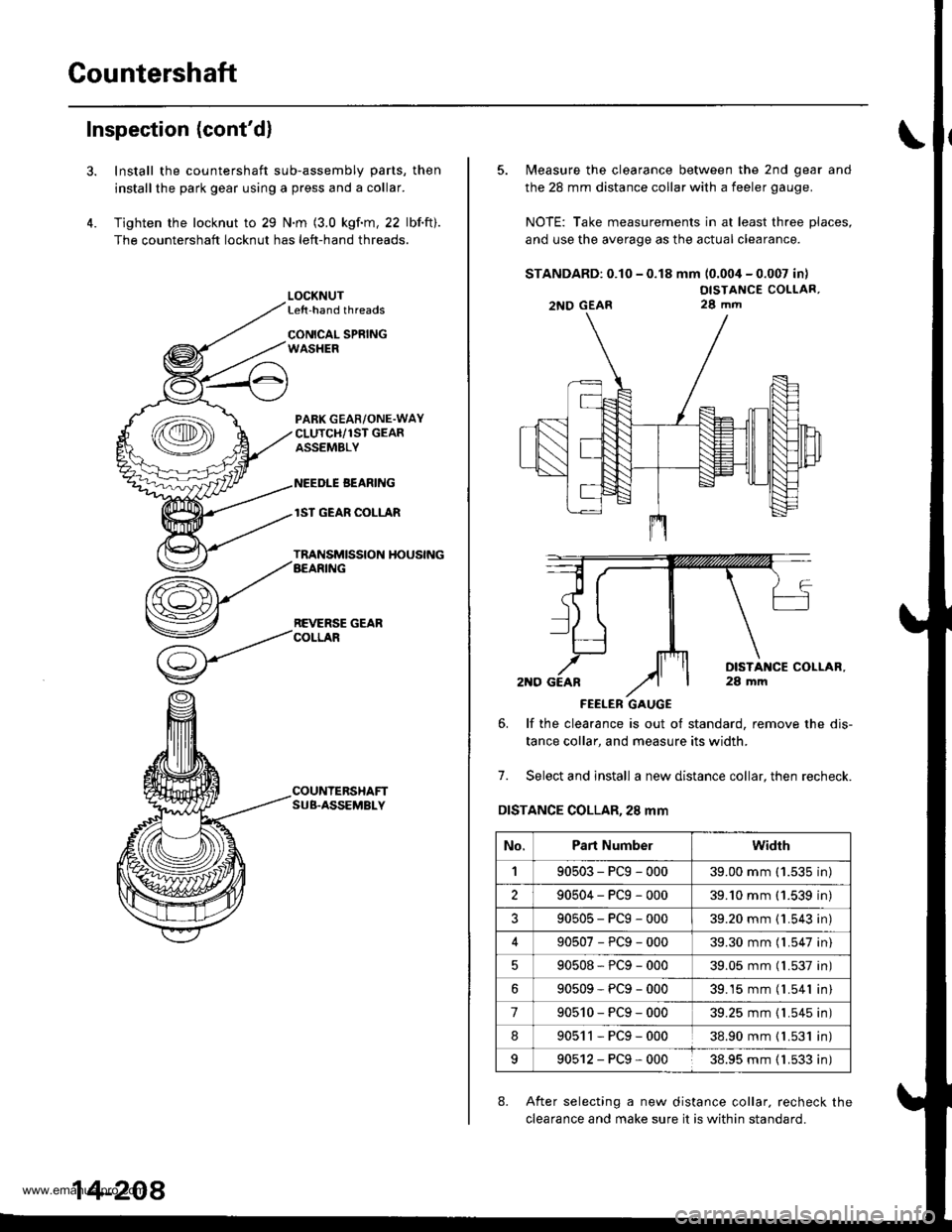
Install the countershaft sub-assembly parts, then
installthe park gear using a press and a collar.
Tighten the locknut to 29 N.m (3.0 kgf.m, 22 lbf.ft).
The countershaft locknut has left-hand threads.
LOCKNUTLe{t-hand threads
CONICAL SPRINGWASHER
PABK GEAR/ONE.WAYCLUTCH/1ST GEARASSEMBLY
NEEDLE BEANING
lST GEAR COLLAR
TRANSMISSION HOUSINGAEARING
REVERSE GEARCOLLAR
COUNTERSHAFTSUB.ASSEMBLY
14-208
5. Measure the clearance between the 2nd gear and
the 28 mm distance collar with a feeler gauge.
NOTE: Take measurements in at least three places,
and use the average as the actual clearance.
STANDARD: 0.10 - 0.18 mm (0.004 - 0.007 in)
OISTANCE COLLAR,28 mm
FEELER GAUGE
6. lf the clearance is out ot standard, remove the dis-
tance collar, and measure its width.
7. Select and install a new distance collar, then recheck.
DISTANCE COLLAR,28 mm
8. After selecting a new distance collar. recheck the
clearance and make sure it is within standard.
2NO GEAR
No.Part Numberwidrh
190503-PCg-00039.00 mm ('1.535 in)
290504-PCg-00039.'10 mm (1.539 in)
?90505-PCg-00039.20 mm {1.543 in)
90507-PCg-00039.30 mm (l.547 in)
90508*PCg-00039.05 mm (l.537 in)
90509-PCg-00039.15 mm (l.541 in)
790510-PCg-00039.25 mm {1.545 in)
890511-PCg-00038.90 mm { L531 in)
990512-PCg-00038.95 mm ( 1.533 in)
www.emanualpro.com
Page 727 of 1395
Disassembly/Reassembly
1.Remove the ATF guide cap by pushing the sub-shaft
inside the transmission housing.
Remove the 1st-hold clutch assembly by pulling,
then removing the sub-shaft.
Install new O-rings on the sub-shaft.
NOTE: Wrap the shaft splines with tape to prevent
damaging the O-rings.
Place the sub-shaft in the transmission housing,
and install the'lst-hold clutch assembly,
Install the new ATF guide cap using the special
tools. Install it in the direction shown.
ATTACHMENT,32x35mm07746 - 0010t00
14-211
www.emanualpro.com
Page 728 of 1395

Sub-shaft Bearings
Replacement
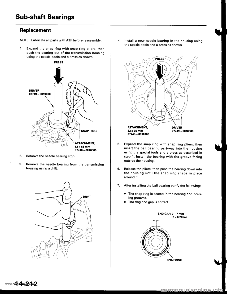
NOTE: Lubricate all parts with ATF before reassembly.
1. Expand the snap ring with snap ring pliers. thenpush the bearing out of the transmission housing
using the special tools and a press as shown.
Remove the needle bearing stop.
Remove the needle bearing from the transmission
housing using a drift.
ATTACHMENT,ai:l x 68 mm07746 - 00105q)
14-212
SNAP RING
4. Install a new needle bearing in the housing using
the sOecial tools and a oress as shown.
7.
cI
32x35mm077/46 - qt10t(x,
Expand the snap ring with snap ring pliers, then
insert the ball bearing part-way into the housing
using the special tools and a press as described in
step 1. Install the bearing with the groove facing
outside the housing.
Release the pliers, then push the bearing down into
the housing until the snap ring snaps in place
around it.
After installing the ball bearing verify the fottowing:
. The snap ring is seated in the bearing and hous-
Ing grooves.
. The ring end gap is correct.
ENDGAP:0-7mml0 - 0.28 inl
www.emanualpro.com
Page 741 of 1395
Oil Seal Replacement
1. Remove the oil seal from the transmission housing.
OIL SEALReplace.
Remove the oil seal from the torque converter
housing.
OIL SEALReplace.TOROUE CONVERTERHOUSING
-.].
3. lnstall the oil seal in the transmission housing using
the special tools as shown.
DRIVER077a9 - 0010000
ATTACHMEMT079r? - slx[ax)
4.Install the oil seal in the torque converter housing
using the specialtools as shown.
14-225
www.emanualpro.com
Page 742 of 1395

Differential
Side Clearance Inspection
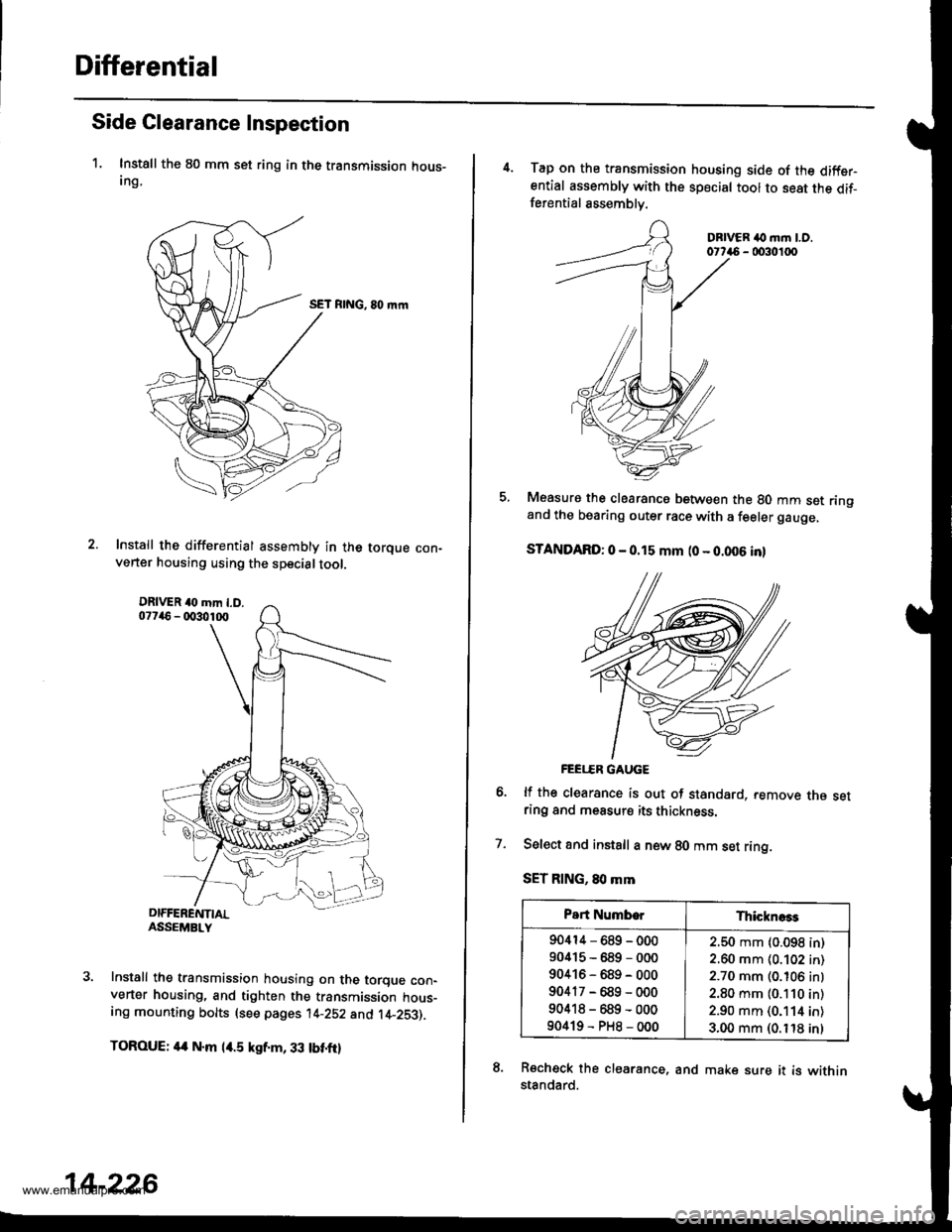
1. Instsll the 80 mm set ring in the transmission hous-Ing,
SET RING, 80 mrn
Install the differential assembly in the torque con-verter housing using the specialtool.
Install the transmission housing on the torque con-verter housing, and tighten the transmission hous-ing mounting bolts (see pages 14-252 and t4-253).
TOROUE: 4a N.m l/r.5 kgf.m, 33 tbt.ftl
14-226
4. Tap on the transmission housing side of the diffsrential assembly with the special tool to seat the dif-ferential assemblv.
DBIVER ilo m.n LO.0t746 - 0030100
Measure the clearancs between the 80 mm set ringand the bearing outer race with a feeler gauge,
STANDARD: 0 - 0.15 mm (0 - 0.006 inl
FEEI..ER GAUGE
lf the clearance is out of standard, remove rne setring and measurs its thickness.
Select and instsll a new 80 mm set ring.
SET RING, 80 mm
Recheck the clearance, and make sure it is withinstandard.
7.
Part NumborThicknoss
90414-689-000
90415-689-000
90416-689-000
90417-689-000
90418-689-000
90419-PH8-000
2.50 mm (0.098 in)
2.60 mm (0.102 in)
2.70 mm (0.106 inl
2.80 mm (0.110 in)
2.90 mm (0.114 in)
3.00 mm (0. t'18 inl
www.emanualpro.com
Page 743 of 1395

Transmission Housing Bearings
Mainshaft/Countershaft Bearings Replacement
1. Expand each snap ring with snap ring pliers, then
push the bearings out of the transmission housing
using the special tools and a press as shown.
Do not remove the snap rings unless it's necessary
to clean the grooves in the housing.
DFIVER077a9 - 001(xx)o
ATTACHMENT
ATTACHMENT
. Mainshaft Bearing Romoval:
ATTACHMENT, 72 x 75 mm
077/16 - 0010600
. Countqrshaft Bearing Removal:
ATTACHMENT, 62 x 68 mm
07746 - 0010500
MAINSHAFT BEARING
4.
Expand each snap ring with snap ring pliers, then
coat the new bearings with ATF and insert them
part-way into the housing using the special tools
and a press as shown. Install the bearings with the
groove facing outside the housing.
Release the pliers, then push the bearings down
into the housing until the rings snap in place
around them.
077/49 - 0010000
ATTACHMENT
. Mainshaft Bearing Installation:
ATTACHMENT,72 x 75 mm
07746 - 0010600
. Countershaft Bearing Instsllation:
ATTACHMENT, 52 x 68 mm
077'16 - 0010500
After installing the bearings, verify the following:
. The snap rings are seated in the bearing and
housrng grooves.
. The snap rings do not bind.
. The ring end gaps are correct,
l0 - 0.28 in)
SNAP RING
ENDGAP:0-7rnm
14-227
www.emanualpro.com
Page 744 of 1395

Transmission Housing Bearings
Sub-shaft Bearing Replacement
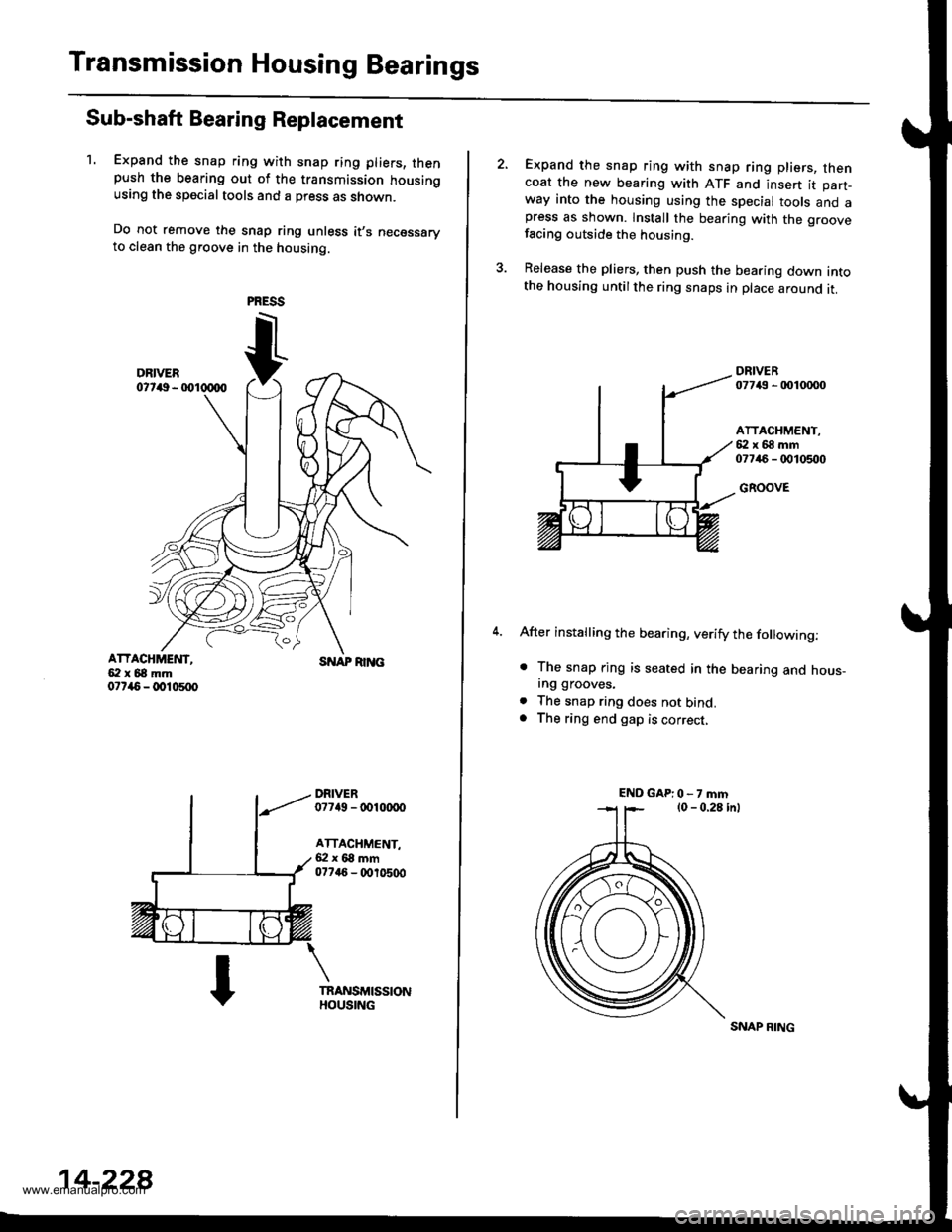
1. Expand the snap ring with snap ring pliers, thenpush the bearing out of the transmission housingusing the special tools and a press as shown.
Do not remove the snap ring unless it,s necessaryto clean the groove in the housing.
ATTACHMEI{T,5:l x 68 mm07r{5 - @10500
SNAP RI]TG
DRIVER07749 - tDl(xx)o
ATTACHMENT,6:l x 68 mm077a6 - (X,r0500
14-228
SNAP RING
Expand the snap ring with snap ring pliers, thencoat the new bearing with ATF and insert it part-way into the housing using the special tools and apress as shown. lnstall the bearing with the groovefacing outside the housing.
Release the pliers, then push the bearing down intothe housing untilthe ring snaps in place around it.
DRIVER07743 - 0010mo
ATTACHMENT,{i:l x 68 mm07746 - 0010500
GROOVE
After installing the bearing, verify the following:
. The snap rjng is seated in the bearing and hous_ing grooves.
. The snap ring does not bind.. The ring end gap is correct,
ENDGAP:0-7mm
www.emanualpro.com
Page 745 of 1395
Torque Gonverter Housing Bearings
Mainshaft Bearing/Oil Seal Replacement
1. Remove the mainshaft bearing and oil seal using
the soecial tool.
SLIDE HAMMER,3/8" - 16(Commercially available)
ADJUSTABLE EEARINGPULLER,25 - 40 mm07736 - A010008 or07736 - A01000A
ATTACHMENT,62x68mm07746 - 0010500
Install a new mainshaft bearing until it bottoms in
the torque converter housing.
3. Install a new oil seal flush with the torque converter
housing.
ATTACHMENT,
07?46 - 0010m0
07749 - 0010000
14-229
www.emanualpro.com