Page 1268 of 1395

Power Mirrors
Function Test
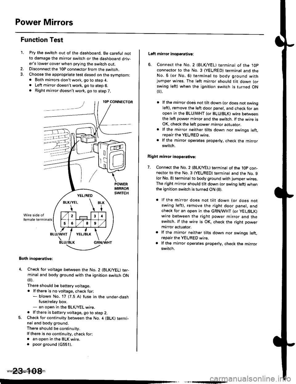
1.Pry the switch out of the dashboard. Be careful notto damage the mirror switch or the dashboard driv-er's lower cover when prying the switch out.Disconnect the 10P connector from the switch.Choose the appropriate test dased on the symptom:. Both mirrors don't work, go to step 4.. Left mirror doesn't work, go to step 6.. Right mirror doesn't work, go to step 7.
Both inoperative:
4. Check for voltage between the No. 2 (BLVYEL) ter-minal and body ground with the ignition switch ON
fl r).
There should be baftery voltage,. lf there is no voltage, check for:- blown No. 17 (7.5 A) fuse in the under-dashfuse/relay box.- an open in the BLK,/YEL wire.. lf there is battery voltage, go to step 2.5. Check for continuity between the No. 4 {BLK) termi-nal and body ground.
There should be continuity.
lf there is no continuity, check for;. an open in the BLK wire.. poor ground (c551).
,
-.t-..------'-
23-108
Left mirror inoperative:
6. Connect the No. 2 {BLKI/EL) terminal of the ,l0p
connector to the No. 3 (YEUREDI terminal and theNo.5 (or No.6) terminal to body ground withjumper wires. The left mirror should tilt down (or
swing left) when the ignition switch is turned ON t).
lf the mirror doei not tilt down (or does not swingleft), remove the left door panel, and check for anopen in the BLUMHT (or BLU/BLK) wire betweenthe left power mirror and the switch. lf the wire isOK, check the left power mirror actuator,
lf the mirror neither tilts down nor swings left,repair the YEURED wire.
lf the mirror operates properly, check the mirrorswitch.
Right mirror inoperaiiva:
7. Connect the No. 2 {BLVYEL) terminat of the 1Op con-nector to the No. 3 (YEURED) terminal and the No. 9(or No. 8) terminal to body ground with jumper wires.The right mirror should tilt down (or swing left) whenthe ignition switch is turned ON l).
. lf the mirror does not tilt down (or does notswing left), remove the right door panel, andcheck for an open in the GRN,4TVHT (or yEUBLK)
wire between the right power mirror and theswitch. lf the wire is OK, check the right power
mtrror actuator.
. lf the mirror neither tilts down nor swings left.repair the YEURED wire.. lf the mirror operates properly, check the mirrorswitch.
www.emanualpro.com
Page 1270 of 1395
Rear Window Defogger
Gomponent Location Index
FUSE/RELAY BOX
REAB WINDOW DEFOGGER SWTTCHInput Test, p89e 23-113
REAR WINDOW DEFOGGERFunction Test. page 23-112DetoggerWre Repair, page 23-112
rr^ja} aia al Irl
!
23-110
www.emanualpro.com
Page 1274 of 1395
Wipers/Washers
Component Location Index
SRS components are located in this area. Review the SRs component locations, precautions, and procedures in the s6ssection (24) before performing repairs or service.
REAB WINDOW WIPER MOTOBT€st, page 23-120WPSR/WASHER SWITCHTest. page 23- l't9
REAR WINDOW WIPERCONTROL UNlT 137 mod.llInput test. page 23-118
WINDSHIELD WIPER MOTORTost, page 23-119
UNDER.DASH FUSE/RELA
INTERMITTENT W|PEN RELAYCIBCUIT, REAR WINDOW INTERMTNENTwlPER RELAY CIBCUIT l'98 - 0O mod.t.lBOX (ln the integrated control unit)Input test, page 23-68
23-114
-
n
tff
www.emanualpro.com
Page 1278 of 1395

Wipers/Washers
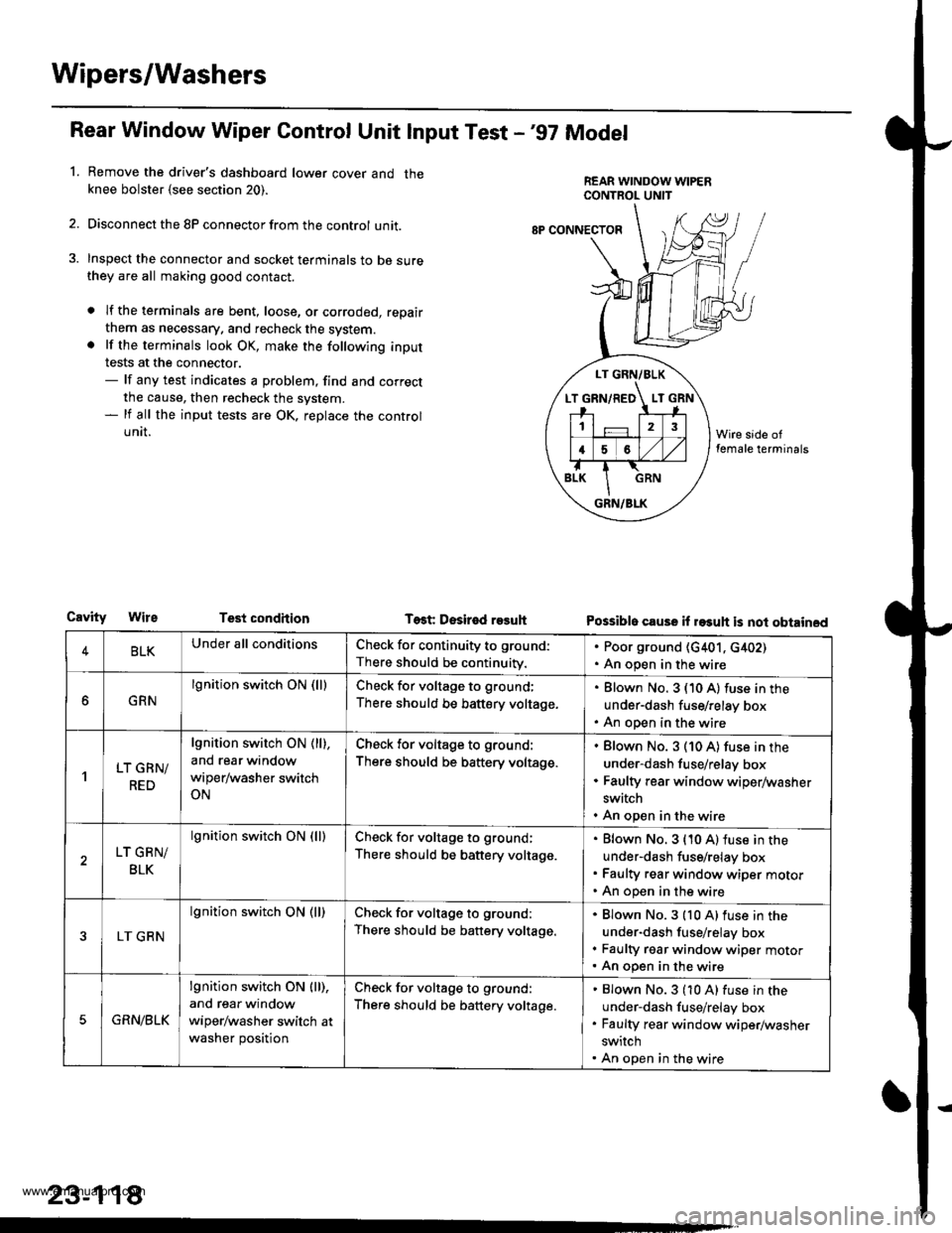
Rear Window Wiper Gontrol Unit lnput Test -'97 Model
Remove the driver's dashboard lower cover and theknee bolster {see section 20).
Disconnect the 8P connector from the control unit.
Inspect the connector and socket terminals to be surethey are all making good contact.
a lf the terminals are bent, loose, or corroded, repair
them as necessary. and recheck the system.. lf the terminals look OK, make the following input
tests at the connector.- lf any test indicates a problem, find and correct
the cause, then recheck the system.- lf all the input tests are OK, replace the control
UNII.
1.
LT GRN/BLK
T GRN/RED LT
12
16
GRN/BLK
8P CONNECTOF
CavityTest condhion Test Desir€d r93uhPossible cause il rasuh is not obtained
4BLKUnder all conditionsCheck for continuity to ground:
There should be continuity.
. Poor ground (G401, c402). An open in the wire
GRN
lgnition switch ON (lllCheck for voltage to ground;
There should be battery voltage.
Blown No. 3 (10 A) fuse in the
under-dash fuse/relay box
An open in the wire
'lLT GRN/
RED
lgnition switch ON ( ll),
and rear window
wiper/washer switch
ON
Check for voltage to ground:
There should be battery voltage.
Blown No. 3 (10 A) fuse in the
under-dash fuse/relay box
Faulty rear window wiper/washer
switch
An open in the wire
LT GRN/
BLK
lgnition switch ON (lllCheck for voltage to ground;
There should be battery voltage.
Blown No. 3 {10 A) fuse in the
under-dash fuse/relay box
Faulty rear window wiper motor
An open in the wire
LT GRN
lgnition switch ON (ll)Check for voltage to ground:
There should be battery voltage.
Blown No.3 {10 A)fuse in the
under-dash fuse/relay box
Faulty rgar window wiper motorAn open in the wire
5GRN/BLK
lgnition switch ON lll),
and rear window
wiper/washer switch at
washer position
Check for voltage to ground:
There should be battery voltage.
Blown No.3 (10 A) fuse in the
under-dash fuse/relay box
Faulty rear window wiper/washer
switch
An open in the wire
23-118
www.emanualpro.com
Page 1312 of 1395
Component/Wiring Locations Index -'97 model
SRS INDICATOR LIGHT (ln the gauge assembly)Troubleshooting, page 24-27Gauge assembly, section 23
DASHBOABD w|RE HARNESS
to SBS INDICATOR LIGHT in
DRIVER'S AIBMGReplacement,page 21-87Disposal, page 24-97
To CRUISE CONTROLSET
To DRIVERS AnBAG
ANBAG2P
sBsitAr[ ] nNEssto FROI|T PASSEiIGEB.S
FRONT PASSEITGER'S AIRBAGReplacement, pago 24{9Disposal, page 24-97
sns ut{fTGROUND
SES MAIN HAR]GSStosns U nItP OOIIITECTOR
MAIN WIRE HABNESSto DASHBOABD wlRE21P
SRS MAIN HABNESSto UNOEB-DASHFUSE/BELAY BOX2P CONNECTOR
GOf$ECrOn PPIlBLr( 8R t
MEMORY ERASE SIGNALIMES) CONNECTOR I2PI[GRY. GRYI or twHT, BLr.l
GAUGE ASSEMBLY5P
HARNESS
SRS MAIN HARNESSto MAINWIRE HARNESS3P OONNECTOR
24-15
www.emanualpro.com
Page 1313 of 1395

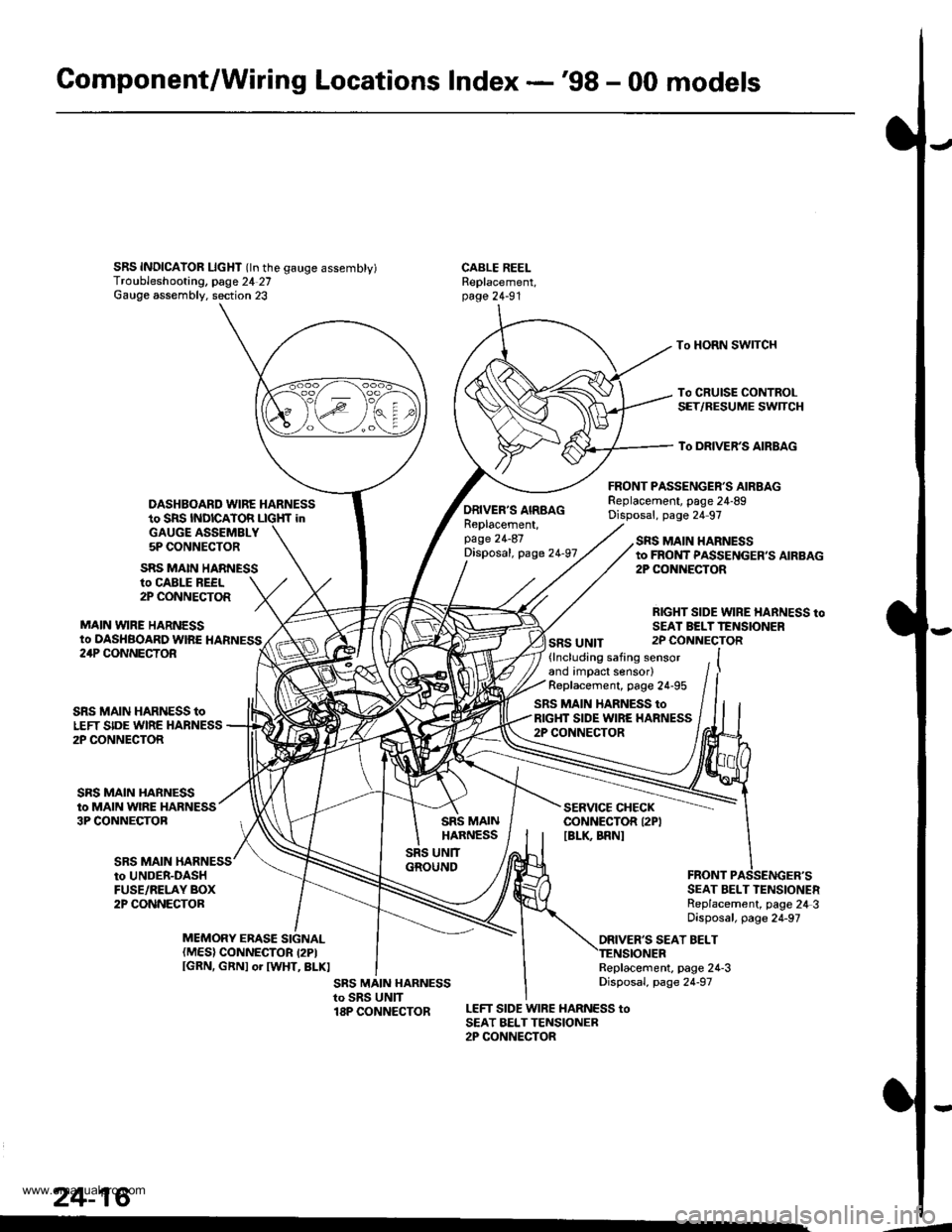
Gomponent/Wiring Locations Index -'98 - 00 models
SRS INDICAIOR LIcHT (ln the gauge assembty)Troubleshooting, page 24 27Gauge assembly. section 23
DASHBOARD WIRE HARNESSto SRS INDICATOR LIGHf inGAUGE ASSEMBLY5P CONNECTOR
FRONT PASSENGER'S AIRBAGReplacement, page 24-89Disposal, page 24 97
CABLE REELReplacement,page 24-91
To HORN SWITCH
To CRUISE CONTROLSET/RESUME SWTCH
To DRIVER'S AIRBAG
ro CABLE REEL2P CONNECTOR
MAIN VYIRE HARNESSto DASHBOARD WIRE HARNESS
SRS MAIN HARNESS
ORIVER'S AIRBAGReplacement,page 24-87Disposal, page 24-97
SRS UNIT
SRS MAIN HARNESSto FROI{T PASSENGER,S AIRBAG2P CONiIECTOR
RIGHT SIDE WIRE HARNESS toSEAI BELTTENSIONER2P CONNECTOR24P CONNECTOR
SRS MAIN
SRS MAIN HARNESS toLEFT SIDE WIRE HARNESS2P CONNECTOR
SRS MAIN HARNESSto MAIN WIRE HARNESS3P CONNECTOB
(lncluding safing sensorand impact sensor)Replacement, page 24-95
SRS MAIN HARNESS toRIGHT SIDE WIRE HARNESS2P CONNECTOR
SERVICE CHECKCONNECTOR I2PIIBLK BRNI
to UNDER-DASHFUSE/RELAY BOX2P CONNECTORSEAT BELT TENSIONERReplacement, page 24 3Disposal, page 24-97
ORIVER'S SEAT BELTMEMORY ERASE SIGNAL(MES) CONNECTOR I2PIIGRN, GRNI or IWHT, BLKIReplacement, page 24-3Disposal, page 24-97
LEFT SIDE WIRE HARNESS toSEAT BELTTENSIONER2P CONNECTOR
24-16
.4
www.emanualpro.com
Page 1315 of 1395
Circuit Diagram
UNDER.DASHFUSE/RELAYBOX
NOTE: The SRS main harness uses all GRY('97 model) or GRN ('98 - 00 models) wires.
WHT/BLK -'- WHT
DRIVEB'SAIRBAGNFLATOR
A
#+
tt tll./ d I
GRY GRY(GRN) (GRN)
FRONTPASSENGER'SALRBAGINFLAlOR
tlGRY GFY(GFN) (GRN)
DRIVER'SSEAT EELTTENSIONER
FRONTPASSENGERSSEAT BELTTENSIONEF
GRN(BLU/PNK)
BLK
G401
24-18
PCM/ECM SERVICE MEMORY ERASECHECK S GNAL (MES)CONNECTOB CONNECTOR(2P)
DATA LINXCONNECTOR(Drc) (r6P)
Models)('98 - 00
IGNITION SWITCHUNDEF,HOOD FUSE/RELAY BOX
YEUGRN
+
PGM FImam relay
SFS INDICATOR CIRCUIT(ln lhe gauge assembly)
Shill loc* so enoid
BLU
GR\
GNY GRY
H
GFY GRYlcFNt (GlN)
??
I r-?LT BLU BRN BRN
tttr?F?F
VVV
SRS NDICATORL GHT {r.4W)
5 12 4 11 | 16 17 15 I 18 I
10 14 113
U
S8S UN T TERMINALS
3567I
101114151718
Terminal side of male terminals
-4
www.emanualpro.com
Page 1322 of 1395

)Steering-related Precautions
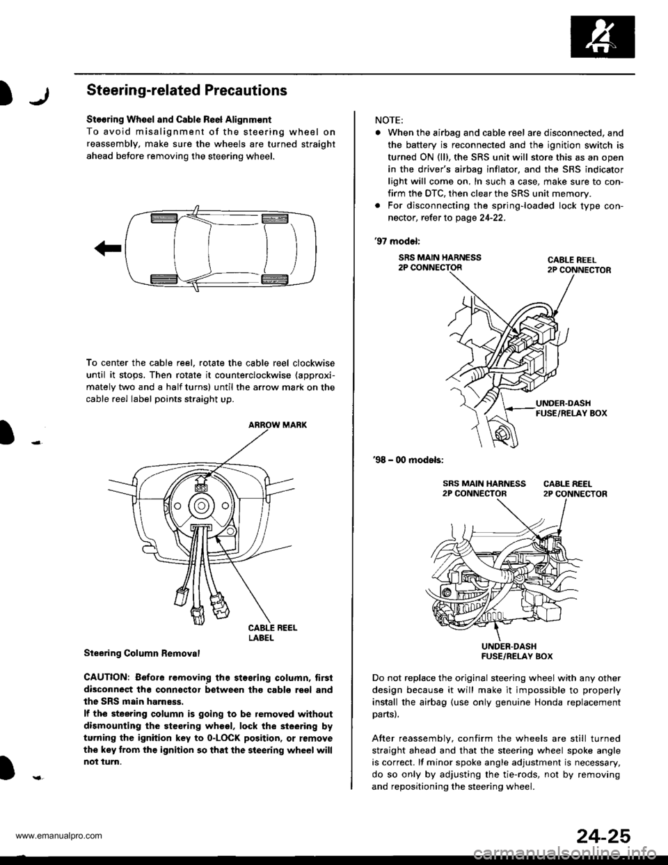
Stooring Wh€el and Csble Re6l Alignm€nt
To avoid misalignment of the steering wheel on
reassembly, make sure the wheels are turned straight
ahead beJore removing the steering wheel.
To center the cable reel, rotate the cable reel clockwise
until it stops, Then rotate it counterclockwise (approxi-
mately two and a half turns) until the arrow mark on the
cable reel label points straight up.
Steering Column Bemoval
CAUTION: Before removing the stosring column, tirsi
disconneqt tha connsctor between tho cabls roel and
the SRS main harness.
lf the steering column is going to be removed without
dismounting the steering wheel, lock the sieering by
turning the ignition key to o-LOCK position, or remove
the key trom the ignition so that the steering wheel will
not turn.
LABEL
NOTE:
. When the airbag and cable r6el are disconnected, and
the battery is reconnected and the ignition switch is
turned ON (ll), the SRS unit will store this as an open
in the driver's airbag inflator, and the SRS indicator
light will come on, In such a case, make sure to con-
firm the DTC, then clear the SRS unit memory.
. For disconnecting the spring-loaded lock type con-
nector, refer to page 24-22.
'97 model:
SRS MAIN HARNESS2P CONNECTORCABLE REEL2P CONNECTOR
'98 - 00 models:
UNDER-DASHFUSE/RELAY BOX
Do not replace the original steering wheel with any other
design because it will make it impossible to properly
install the airbag (use only genuine Honda replacement
partsl.
After reassemblv, confirm the wheels are still turned
straight ahead and that the steering wheel spoke angle
is correct. lf minor spoke angle adjustment is necessary,
do so only by adjusting the tie-rods, not by removing
and repositioning the steering whee .
24-25
www.emanualpro.com