2000 HONDA CIVIC Top
[x] Cancel search: TopPage 2 of 2189

INTRODUCTION
How to Use This Manual
This manual contains information for the 1996 - 2000 ClVlC. lt is
divided into 24 sections. The first page of each section is marked
with a black tab that lines up with its corresponding thumb index
tab on this page and the back cover. You can quicklY find the first
page of each section without looking through a tull table ol con_
tents. The symbols printed at the top corner of each page can also
be used as a quick reference system.
Each section includesl
1. A table of contents, or an exploded view index showing:
. Parts disassemblY sequence.
. Bolt torques and thread sizes.
. Page references to descriptaons in text
2. Disassembly/assembly procedures and tools.
3. Inspection.
4. Testing/troubleshooting.
5. Repair.
6. Adjustments.
Special Information
!@ Indicates a sttong possibility of sover. perconal iniurY
or loss ol lite if in3tructions are not follow€d.
GAUTION: Indicaiqs a possibility ot p€lsonal injury or 6quipm.nt
damage il instiuc'tions are not followod
t Noncali-. pu.po.. ot thes6 messages is to help provent demage lo lhe
vehicle, other property, or the €nvironment.
NOTE: Gives helpful information.
CAUTfON: Detaifed descriptions ol standard workshop p.oceduro3.
safoty principles and servico operations are not included. Pleaso
note that this manual contain3 wetnings and cautions against
some sp6cific sGrvic€ methods which could cause PERSONAL
INJURY, damage a vohicle or make il unsafe. Ploase undorstand
that these warnings cannot covsr all conceivable weys in which
service. whelher or not iocommgndod bY HONDA. mighi bo done,
or ol tho possiblG hazardou3 consgquonces of ev€aY conceivablg
way, nor could HONDA invqstigato all 3uch way3. AnYono using
sgrvice procedures or lools, whethei or nol rGcommendod bY
HONDA, must srtisty hifisetf thoroughlylhat nohher pefsonal sefety
nor vehiclc satsty will be reopardi2ed.
All intormation contained in this manual is based on the latest prod
uct information available at the time oI printing We reserve the
right to make changes at any time without notice No part of this
publication may be reproduced, stored in retrieval system, or trans'
mitted, in any form by any means, electronic, mechanical, photo
copying, recording, or otherwise, without the prior written permis-
sion of the publisher. This includes text, figures and tables.
*Transaxle
ds
First Edition 8/99 1848 PagesAll Right Reserved
HONOA MOTOR CO., LTD.
Sorvico Publication Offico
As sections with * include SRS components;
sDecial precautions are lequired when servlclng
*Electrical't
*SRSSRS
Page 49 of 2189
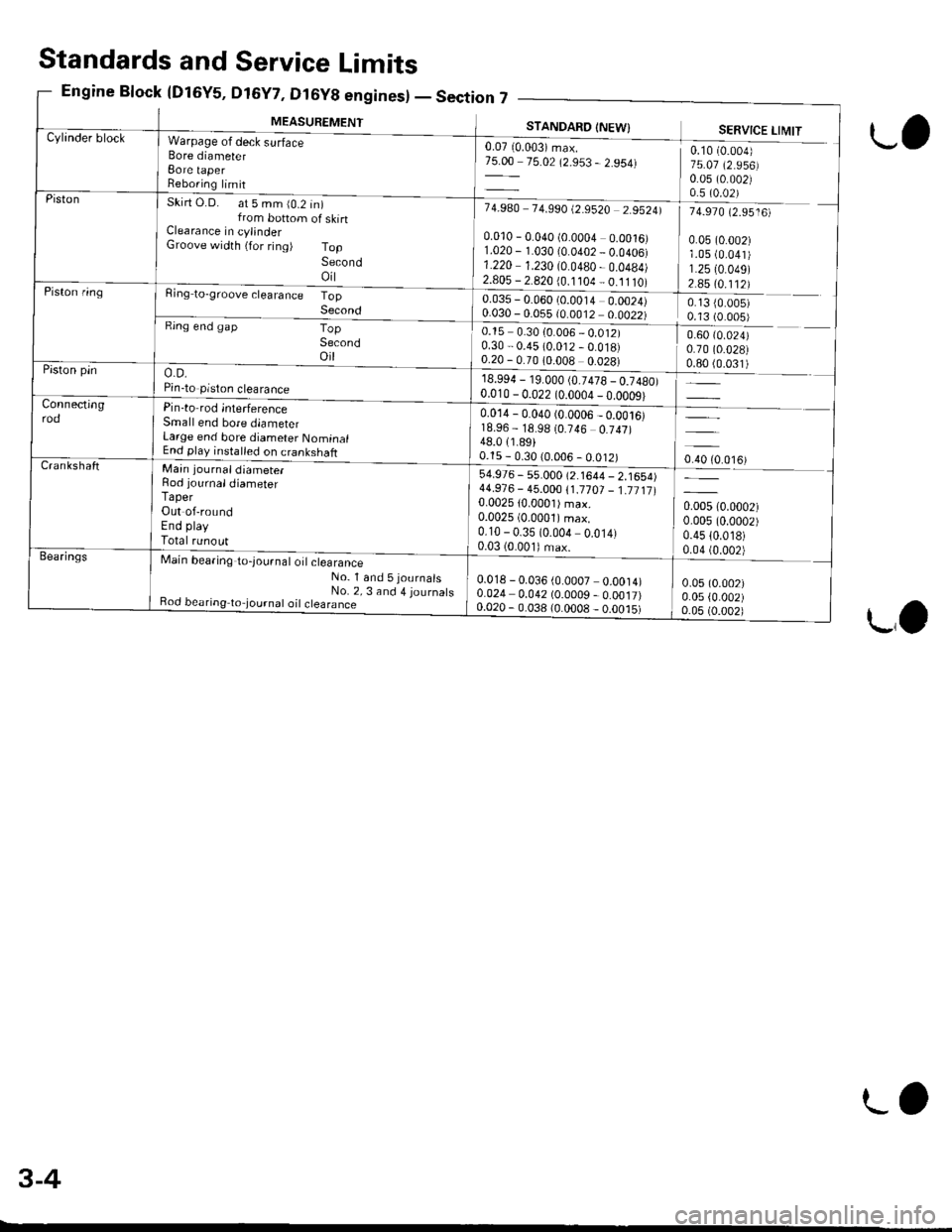
MEASUREMENT
,n7 _--
STANDAFO INEW}
0.07 10.003) max.75.00 75.02 (2.953 - 2.954)
7 4.9A0 7 4.990 t2.9520 2.95241
0.010 - 0.040 (0.0004 0.0016)1.020 - 1.030 10.0402 _ 0.0406)1.220 1.230 (0.0480 - 0.0484)2.805 - 2.820 {0.1 104 _ 0.11 tO)
0.035 - 0.060 (0.0014 0.0024)0.030 - 0.055 {0.0012 0.0022)_
0.15 0.30 {0.006 _ 0.012)0.30 - 0.45 (0.012 - 0.018)0.20 - 0.70 10.008 0.028)
18.994 - 19.000 (0.7478 _ 0.7480)0.010 - 0 0?2 lo oona -n dn^ol
SERVICE LIMIT
0.10 (0.004)
75.07 (2.956)0.05 (0.002)0.5 (0.02)
74.970 (2.9516)
0.05 (0.002)1.05 (0.041)
1.2510.049)2.85 (0.112)
0.13 {0.005)0.13 (0.005)
0.60 (0.024)
0.70 (0.028)
ljqql) _
oro to.o',ur
0.005 (0.0002)
0.005 (0.0002)
0.4510.018)0.04 (0.002)
0.05 (0.002)
0.05 {0.002)0.05 (0.002)
Cylinder blockWarpage of deck surfaceBore diameterBore taperReboring limit
Skirt O.D. at 5 mm (0.2 in)from bottom of skinClearance in cylinderGroove width {for ring) TopSecondoil
Ring to-groove clearance TopSecondRing end gapTopSecondoil
o.D.Pin-to piston clearance
Pin-to rod interferenceSmall end bore diameterLarge end bore diameter NominalEnd play installed on crankshaft
Piston
Piston ring
Piston pin
Connectingrod0.014 - 0.040 (0.0006 _ 0.ool6)18.96 - 18.98 (0.746 0.747)48.011.89)0.15 - 0.30 (0.006 - 0.012)CrankshaftMain journaldiameter
Rod iournaldiameterTaperOut of-roundEnd playTotal runout
Main bearing to-lournal o't clearance-No_ l and 5journals
_ No. 2, 3 and 4 journatsBod bearing to,journat oil ctearance
54.976 - s5.000 (2.1644 - 2.1654)44.91 6 - 45.000 1'1.17 01 _ 1.71 11 10.002510.0001) max.0.0025 (0.0001)max.
0.10 - 0.35 (0.004 0.014)0.03 (0.001) max.Bea.ings
0.018 - 0.036 (0.0007 0.0014)0.024 0.042 (0.0009 - 0.0017)0.020 - 0.038 (0.0008 _ o.oo.t5)
Standards and Service Limits
Engine Block {Dl6Y5, D16Y7, Dt6y8 enginesl - Section
L,
LO
3-4
LO
Page 50 of 2189
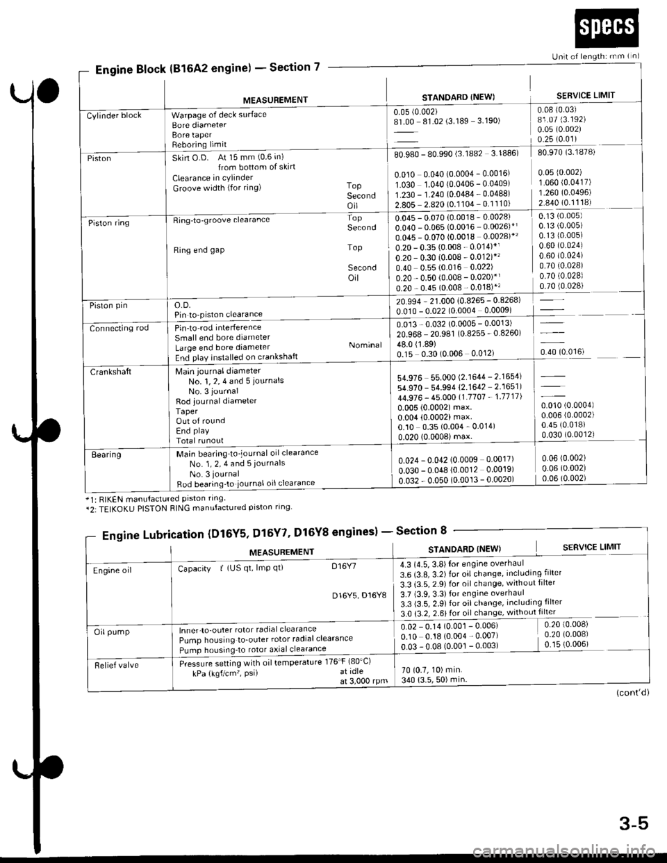
Section 7
Unlt of length: rnm ( n)
Engine Block(816A2 engine) -
MEASUREMENT
Warpage of deck surface
Bore diameterBore taperReboring limit
STANOARD {NEW)
0.05 (0.002)
8L00 81.02 (3.189 3.190)
SERVICE LIMIT
0.08 {0.03)81.07 (3.192)
0.05 (0.002)
0.25 (0.01)
Cylinder block
PistonSkin O D. At 15 mm (0.6 in)
{rom bottom of skirt
Clearance in cylinder
Groove width (for ring) ToPSecondoil
80.980 - 80.990 (3.lUUz 3. rUubl du Y/u lJ. ro/o,
I0.010 0.040 (o.ooo4 - 0.0016' 0 05 r0 002) II O3O 1.040 10.0406 - 0.04091 1 060 {0 0417) |1.230 - 1.?40 {0.0484 . 0.04881 1.260 10.04961 1'*: ?:::i?l:91'::ll:l I::::::= lPiston ringRing-to-groove clearance
Ring end gap
o.D.Pin to-piston clearance
Pin'to rod interference
Small end bore diameter
Large end bore diameterEnd play installed on crankshaft
Main journal diameterNo. 1, 2, 4 and 5 iournalsNo. 3 journal
Rod journal diameterTaperOut of roundEnd play
Total runout
Main bearing to_journal oil clearance
No. 1, 2, 4 and 5 journals
No. 3 journal
Bod bearing'to iournal oil clearance
Second
Top
Secondoil
Nominal
0.13 (0.005)
0.1310.005)0.60 (0.024)
0.60 t0.024)0.7010.028)0.70 (0.028)
,rr]q!4l
-l
u.u45 - u.u/u lu.uu ro
0.040 - 0.065 (0.0016 0.0026)*l
0.045 - 0.070 (0.0018 0.0028)*'
0.20 - 0.35 (0.008 - 0.014)*1
o.20 - 0.30 (0.008 - 0.012)*'�
0.40 0.55 (0.016 0.022)
0.20 - 0.50 (0.008 - 0.020)*'
0.20 - 0.45 (0.008 - 0.018)"
20.994 - 21.000 {0.8265 - 0.8268)
0.010 - 0.022 (0.0004 0.0009)
0.013 - 0.032 (0.0005 - 0.0013)
20.968 20.981 (0.8255 - 0.8260)
lliSlto?,o.oou o.o''r, o.rotoo'ut
Piston pin
Connecting rod
54.976 55.000 (2.1644 - 2.1654)
54.970 - 54.994 (2.1642 2.1651)
44.976 - 45.00011.'1707 - 1.1711|
0.005 (0.0002) max.0.004 (0.0002) max.0.10 0.35 (0.004 - 0.014)
0.020 (0.0008imax.
0.010 (0.0004)
0.006 (0.0002)
0.45 (0.018)
0.030 (0.0012)
Crankshaft
Eearing0.024 - 0.042 (0.0009 0.0017)
o.o3o - 0.048 {0.0012 0.0019)
0.032 - 0.050 (0.0013 - 0.0020)
0.06 (0.002)
0.06 (0.002)
0.06 (0.002)
*1: RIKEN manutactured prston rrng*2:TEIKOKU PISTON RING manufactured piston ring
gineslSection 8
(cont'd)
Engine Lubri,cation (Dl6Y5, Dl5Y7' Dl6Y8 enginesl -
MEASUREMENTSTANOARD (NEW) S€RVICE LIMIT
4.3 (4.5, 3.8)Ior engine overhaul
3.6 (3.8, 3.2) for oil change, including filter
3.3 (3.5, 2.9) for oil change, without filter
3.7 (3.9,3.3)for engine overhaul
3.3 (3.5, 2.9) for oil change, including filter
3.0 {3.2, 2.6} for oil change, without filter
0.02 - 0.14 (O.OO1 - 0.006) 0.20 {0 008)
0.10 0.18 (o.oo4 - 0.007) i 0.20 (0 008)
o 03 !.08 (qool!.oo3l _ (0 006) -
70 (0.7, 10) min.
340 (3.5,50) min
Engine oilCapacity | (US qt, lmp qt) D16Y7
D16Y5 D16Y8
lnner-to-outer rotor radial clearance
Pump housing to_outer rotor radialclearance
Pumo housrnq_to rotor a)rial clearance
Pressure setting with oil temperature 176'F (80'Ci
kPa (kgf/cm'�, PsiI at idleat 3,000 rpm
Oil pump
Relief valve
3-5
Page 110 of 2189

Engine Removal/lnstallation
Installation (cont'd)
Except CVT:
12 x 1.25 mm64 N.m (6.5 kgd.m,
Tighten the bolts/nut on the left front mount in thenumbered sequence shown {O - @).
(t 12 x 1.25 mm83 N'm (8.5 kgf.m,61 tbt.trl
/+4 N.m 14.5 kgf.m,33 lbt.trl
O 12 r 1.25 mm59 N.m 16.0 kgt.m,43 tbt.rtlSeplace.
5-16
\
7. Perform the following:
. Clean the areas where the driveshaft(s) and theintermediate shaft contact the transmission (dif_ferential) thoroughly with solvent or carburetorcteaner, and dry with compressed air.. Check that the set rings on the ends of the drive_shaft and intermediate shaft click into place.CAUTION: Use new set rings,. Adjust the shift cable (see section 14).. Adjust the throttle cable (see section 11).. Adjust the cruise control cable (see section 23).. Refill the engine with engine oil (see page 8-6).. Refill the transmission with fluid (see section 13,14).
. Refill the radiator with engine coolant (see page10-7).
. Bleed air from the cooling system with the heatervalve open (see page j0-7).
. Clean the battery posts and cable terminals withsandpaper, assemble them, then apply grease toprevent corrosaon.. Inspect for fuel leakage (see section j l).After assembling the fuel line, turn on l) the igni_tion switch (do not operate the starter) so that thefuel pump runs for approximately two secondsand the fuel line pressurizes. Repeat this opera_taon two or three times, then check for fuel leak_age at any point in the fuel line,
Page 113 of 2189

Special Tools
(
Ref. No. I Tool Number
o
o
@
@
oor@-1
andO-2
@
o
OTHAH _ PJTOl OB
07JAA - 001010A
07JAB - 0010204
OTLAJ _ PR3O2OB
07NAB - 0010404
07NAJ - P07010A
01406 - 0020201
OTMAJ - PY4O'114
07MAJ - PY40120
07406 - 0070300
07742 - 0010100
Valve Guide Reamer, 5.5 mm
Socket, 17 mm
Holder Handle
Air Stopper
Holder Attachment. 50 mm
Pressure Gauge Adapter
A/f Pressure Hose
A/T Pressure Hose,2,210 mmAy'T Pressure Adapter
A,/T Low Pressure Gauge WPanelValve Guide Driver, 5.5 mm
6-43
6-16
o- to
6-8, 10
6-16
6-4
6-4
6-4
6-4
6-4
6-4't, 42
-rE=-!fT----F
o@
@@
o
O-r
-A\
g
@El
ril
6l
A-2
a
6-2
Page 120 of 2189
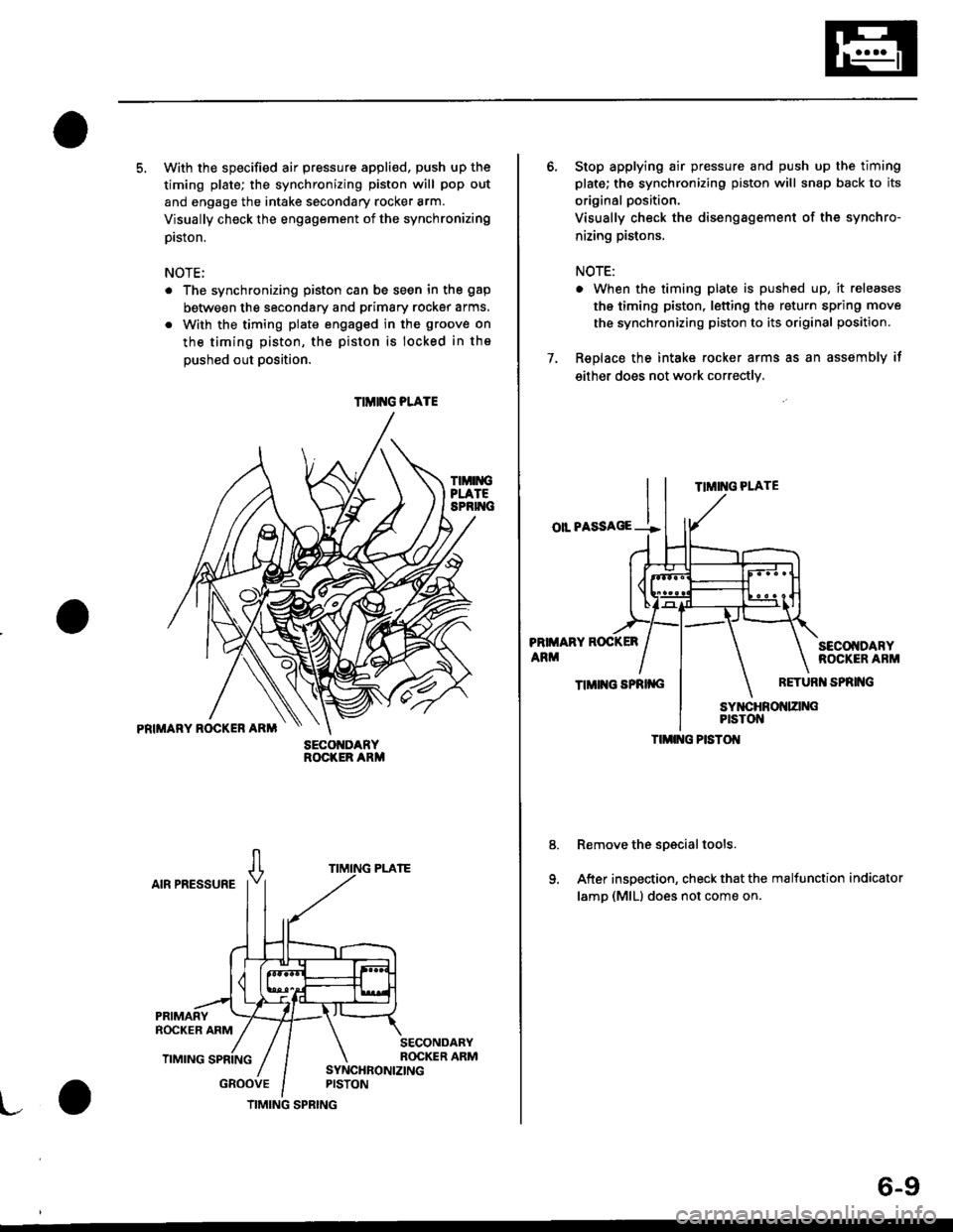
5. With the specified air pressure appli€d, push up the
timing plate; the synchronizing piston will pop out
and engage the intake secondary rocker arm.
Visually check the engagement of the synchronizing
prston.
NOTE;
The synchronizing piston can be seen in the gap
between the secondary and primary rocker arms,
With the timing plate engaged in the groove on
the timing piston, the piston is locked in the
oushed out Dosition.
TIMIiIGPLATESPRIT{C
PRIMARY ROCKER ARM
AIR PRESSURE
GROOVE
SECO DARYROCKER ARM
TIMIT{G PLATE
TIMING SPRING
6-9
6. Stop applying air pressure and push up the timing
plate; the synchronizing piston will snap back to its
original position.
Visually check the disengagement of the synchro-
nizing pistons.
NOTE:
. When the timing plate is pushed up, it releases
the timing piston, letting the return spring move
the synchronizing piston to its original position.
7. Replace the intake rocker arms as an assembly if
either does not work correctly,
TIMING PLATE
oll PASSAGE --!
PRIMARY ROCKER
ARMSECOI{DARYROCKER ARM
TIMII{G SPRII{GRETURI{ SPRING
Remove the spscial tools.
After inspection, check that the malfunction indicator
lamp (MlLl does not come on.
TIMI G PISTOI{
Page 123 of 2189
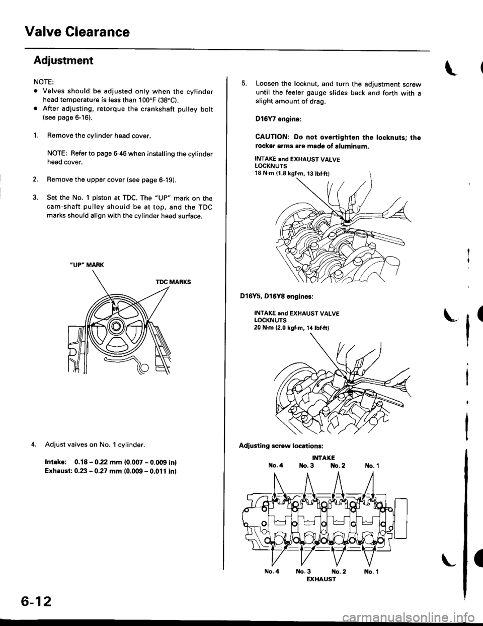
Valve Clearance
Adjustment
NOTE:
. Valves should be adjusted only when the cylindsrhead temperature is less than 100"F (38"C).
. After adjusting, retorque the crankshaft pulley bolt(see page 6-16).
1, Remove the cylinder head cover.
NOTE; Refer to page e46 when installing the cytinderhead cover.
2. Remove the upper cover (see page 6-19).
3. Set the No. 1 piston at TDC. The "UP" mark on the
cam-shaft pulley should be at top, and the TDC
marks should align with the cylinder head surface.
TDC MARKS
4. Adjust valves on No, 1 cylinder.
Intako: 0.18 - 0.22 mm {0.007 - 0.009 in}
Exhaust: 0.23 - 0.27 mm (0.009 - 0.011 inl
"UP" MARK
6-12
No.4
5. Loosen the locknut, and turn the adjustment screwuntil the feeler gauge slides back and forth with asliOht amount of drag,
D16Y7 engin.:
CAUTION: Do not oyertighlen the locknuts; thorockor arms are made of aluminum.
INTAKE end EXHAUST VALVELOCKNUTS
Dl6Y5, Dl6Y8 engin€3:
INTAKE .nd EXHAUST VALVELOCKNUTS20 N.m 12.0 kstm, 14lbtft)
Adiusting screw locations:
IMTAKEo.4 1{o. 3 No. 2
tr'
(
nb.3 No.2 No. 1EXHAUST
18 N.m (1.8 kgI.m, 13 tbl.ftl
Page 125 of 2189
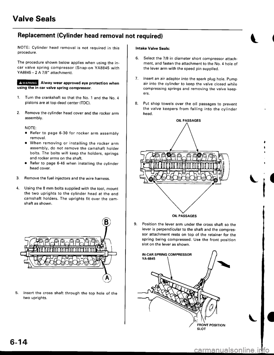
Valve Seals
Replacement (Cylinder head removal not requiredl
NOTE: Cylinder head removal is not required in thisprocedure.
The procedure shown below applies when using the in-
car valve spring compressor (Snap-on YA884S withY48845 - 2 A7/8" attachment).
!@@ Alway wear approved eye protection whenusing ihe in-cai valve spring compressor.
1. Turn the crankshaft so that the No. I and the No. 4pistons are at top dead center (TDC).
2. Remove the cylinder head cover and the rocker arm
assembly.
NOTE:
. Refer to page 6-30 for rocker arm assembly
removat.
. When removing or installing the rocker armassembly, do not remove the camshaft holder
bolts. The bolts will keep the holders, springs
and rocker arms on the shaft.
. Refer to page 6-46 when installing the cylinder
head cover.
Remove the fuel injectors and the wire harness.
Using the 8 mm bolts supplied with the tool. mount
the two uprights to the cylinder head at the end
camshaft holders. The uprights fit over the cam-
shaft as shown.
lnsert the cross shaft through the top hole of thetwo uprights.
3.
4.
6-14
Intake Valve Seals:
6. Select the 7/8 in diameter short compressor attach-ment, and fasten the attachment to the No. 4 hole of
the leve. arm with the speed pin supplied.
8.
7.lnsert an air adapto. into the spark plug hole. pump
air into the cylinder to keep the valve closed whilecompressing springs and removing the valve keepers.
Put shop towels over the oil passages to prevent
the valve keepers from falling into the cylinder
neao.
OIL PASSAGES
Position the lever arm under the cross shaft so thelever is perpendicular to the shaft and the compres-
sor attachment rests on top of the retainer for thespring being compressed. Use the front position
slot on the lever as shown.
,
I
i'
OIL PASSAGES
IN-CAR SPRING COMPRESSOR
SLOT