Page 956 of 2189

Troubleshooting Flowchart - Drive Pulley Speed Sensor
NOTE: Record allfreeze data before you troubleshoot'
Possible Cau3€
. Disconnected diive PulleYsoeed s6n3or connectol. Short or open in drive Pull.Ysooed sonsor wire. FaultY drive PulleY spo€d sen'
301
DRIVE PULEY SPEED
SENSOR @NNEfiOR
Terminal side of male terminals
PCM CONNECTOR D (16PI
NDR SG IGRNI
Wire side o{ Iemale terminals
(cont'd)
14-279
.OBD ll Scan Tool indicates
Code Pl885.. Selt-diagnosb E indicator light
indicatos Code 34
check the drive pulleY sPeed sen-
sor installation, and check it for
damage.
ls the drive PulleY speed sen-
sor installed properly, and not
damaged?
Rein3tall or roplace and techeck
Measuro Drive PulleY Speed Sen_
sor Ro3istanco at the Sonsol
Connector:1. Disconnect the 2P conneclor
from the drive Pulley speed
sensor,2. Measure drive Pulley speed
sensor resislance at the sen-
sor connecror.
ls the resistance 350 - 600 O?
Check Drivo PulleY SP6€d Sen3o.
lor . Short Circuit:1. Disconnect the D {16P) connec-
torlrom the PCM.
2. Check lor continuity between
body ground and the D11 ter
minal and D'l2 terminal indi
vidually.
Repai. short in the wiles
between the Dll lnd D12 termi-
nals and iho drive Pull.Y speed
To page 14-280
Page 957 of 2189
Electrical Troubleshooting ('gg - 00 Models)
Troubleshooting Flowchart - Drive pulley Speed Sensor (cont,d)
PCM CONNECTOR D {16P}
Wire side of temale terminals
From page 14-279
Measure Drivo Pulley Speed Sen-sor Circuit tor an Open:1. Connect the drive pulleyspeed sensor connector,2. lvleasu re the resistancebetween the Dl1 and Dl2 ter-minals.
R6pair loose tgrminal or opan inthe wiros betwo€n tho D1,l .ndOl2 tarminrl! .nd th. drivs pul-ley speed *n3or.
ls the resistance 350 - 600 O?
Ch6ck for loose lerminal tit in thePCM connectors, ll nece3saay,substituto a known-good PCM6nd r€check.
14-280
Page 958 of 2189

Troubleshooting Flowchart - Driven Pulley Speed Sensor
NOTE: Record all freeze data betore you troubleshoot'
Po3sible Caus€
' Oisconnected driven PulleYspeed s6nlor connoctor. Short or opon in d.iven Pulleysoeed sonsol wirc. Faulty driven Pulley speed sen_
sor
DRIVEN PULLEY SPEED
SENSOR CONNECTOR
Terminal side ol male terminals
FCM CONNECTOR D If6P)
NDN IWHTI
Wire side of female terminals
(cont'd)
'OBD lt Sc.n Tool indicates
Code Pl886.. Self-diagnosb E indicator light
indicrt€. Codo 35.
Check the driven Pulley speed
sensor installation, and check it
Ior damage.
lsthe driven pulleY speed sen'
sor installed ProPerly, and not
damaged?
Boin3tall or ropl.ca and recheck.
M..sure Drivon PulloY SPoed
Sonsor Rosblanco at the S6n3or
Conn6ctori1. Disconnect the 2P connector
trom the driven PUlley sPeed
sensor,2. lveasure driven Pulley speed
sensor resistance at the sen_
sor connector.
ls the resistance 350 - 600 0?
Check Dtivon Pulloy SP€ed Sen'
sor for a Short Circuit:
1. Disconnect the D (16P) connec-
torfrom the PCM.
2. Check tor continuity between
body ground and the D10 ter'
minal and Dl6 terminal indi-
vidually.
Raoair shott in tho wi.6s
betwoon th. Dlo end D16 tormi'
nak .nd the ddven Pulley spo€d
Fo page 14'282
14-2A1
Page 959 of 2189
Electrical Troubleshooting ['gg - 00 Models)
Troubleshooting Flowchart - Driven pulley Speed Sensor (cont,dl
NON SG IRED/WHTI
Wire side of female terminals
From page l4 281
M6asure Driven Pulley SpeedSensor Circuit Ior an Op€n:1. Connect the driven pulleyspeed sensor connector,2, Measure the resistancebetween the D10 and Dl6 ter-minals.
Rgpair loose terminal or open inthe wires botwosn the Dlo and016 torminab rnd the drivon Dul-ley speed 3ensoa,
ls the resistance 350 - 600 O?
Check tor loose terminal tit in thePCM connectors, lf necessary,sub3titute a lnown-good PCMand rech6ck.
14-282
Page 960 of 2189

Troubleshooting Flowchart - Secondary Gear Shaft Speed Sensor
NOTE: Record all freeze data before you troubleshoot
Po$ible Causo
. Oisconnectod secondarY gear
shaft speed sensor conn66or' short or open in secondary gear
shaft spe€d sensor wiro. Faulty secondarY gear 3haft
sPeed sensor
SECONDARY GEAR SHAFT
SPEEO SENSOR CONNECTOR
Terminal side of male terminals
PCM CONNECTOR D I15P)
VEL (WHT/REO) VEL SG IALK/WHTI
Wire side oI female terminals
(cont'd)
14-243
' OBD ll Scan Tool indicates
Code P1888.. Self-diagnosis E indicalor light
indicats Code 35.
Check the secondarY gear shaft
speed sensor installation, and
check it for damage.
ls the secondary gear shaft
speed sensor installedproperly, and not damaged?
Reinatall or replace and rocheck.
Measure SocondarY Gear Sh.ft
Speed Sen3or Resistance at the
Sensor Connector:1. Disconnect the 2P connector
trom the secondary gear shaft
speed sensor.2. Measure secondary gear shaft
speed sensor resistance at the
sensor connector.
ls the resistance 350 - 600 0?
Check SecondarY Gear Shaft
Speed Sensor lor a Short Circuit:
1. Disconned the D (16P) connec-
tor from the PCM.
2. Check for continuity between
body ground and the D1 ter-
minal and D7 terminal indi-
vidually.
Repair short in the wiros
b.tween the Dl and D7 termi_
ne13 and th€ secondarY geal
3haft lpeed sonsor.
To page 14-284
Page 961 of 2189
Electrical Troubleshooting ('gg - 00 Modelsl
Troubleshooting Flowchart - Secondary Gear Shaft Speed Sensor (cont'd)
Wi16 side of female t6rminals
From page 14 283
Moasu.€ Secondary Gaar ShaftSpo6d Sonsor Circuit tor anOpeni1. Connect the secondary gearshaft sp6ed sensor connector,2. M easu re the resistancebetween the Dl and D7 terminals,
Repair looao terminal or opon inthe wiraa batuvacn the Dl and D7t.rminrls snd the second!rygeer rhatt 3peod 3.nior.
ls the resistance 350 - 600 O?
Check for looso terminal lit in thePCM connectors. lf necessary,substilute a known-good PCM.nd recheck.
14-284
Page 963 of 2189

Electrical Troubleshootang ('gg - 00 Models)
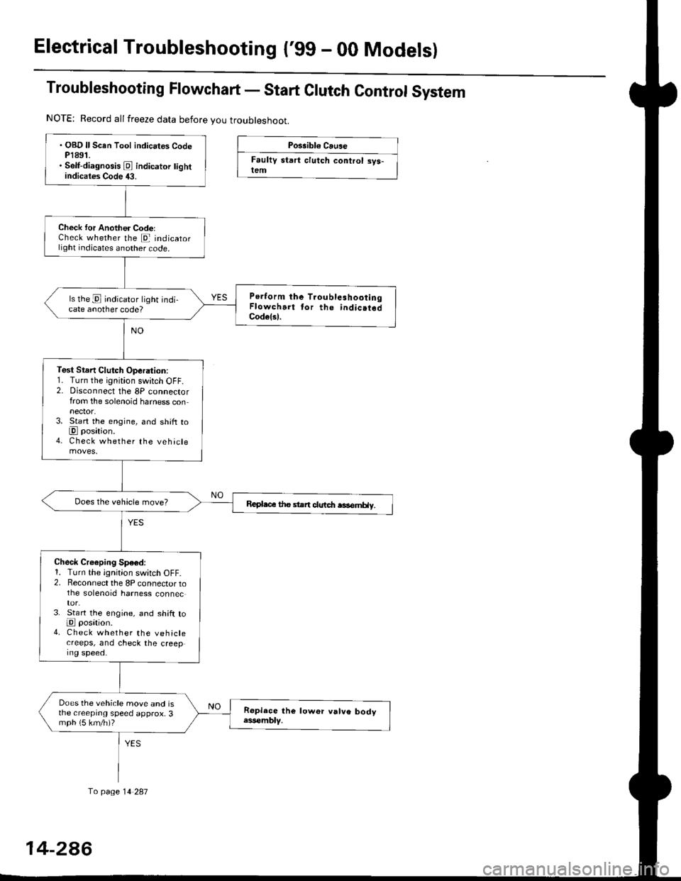
Troubleshooting Flowchart - Start Clutch Control System
Possibl€ Cause
Faultv start clutch control sys-lem
NOTE: Record allfreeze data before you troubleshoot.
fo page 14 287
. OBD ll Scan Tool indicates CodeP1891.. Self-diagnosis E indicator tightindicates Code 43.
Check for Another CodelCheck whether the E indicatorlight indicates another code.
Perform the TroubleshootingFlowchart tor the indic.tedCodelsl.
ls the E indicator light indi-cate another code?
Test Stsn Clutch Operation:1. Turn the ignition switch OFF.2. Disconnect the 8P connectorfrom the solenoid harness connector.3. Start the engine, and shift toE position.4. Check whether the vehiclemoves.
Repl.c€ the stan clutdt rasemHy.
Check Croeping Sp€6d:1. Turn the ignition switch OFF.2. Reconnect the 8P connector tothe solenoid harness connec
3. St€rt the engine, and shift toE posation.4. Check whether the vehiclecreeps, and check the creeping speed.
Does the vehicle move and isthe creeprng speed approx, 3mph (5 km/h)?
14-2A6
Page 965 of 2189

Electrical Troubleshooting ('99 - 00 Models)
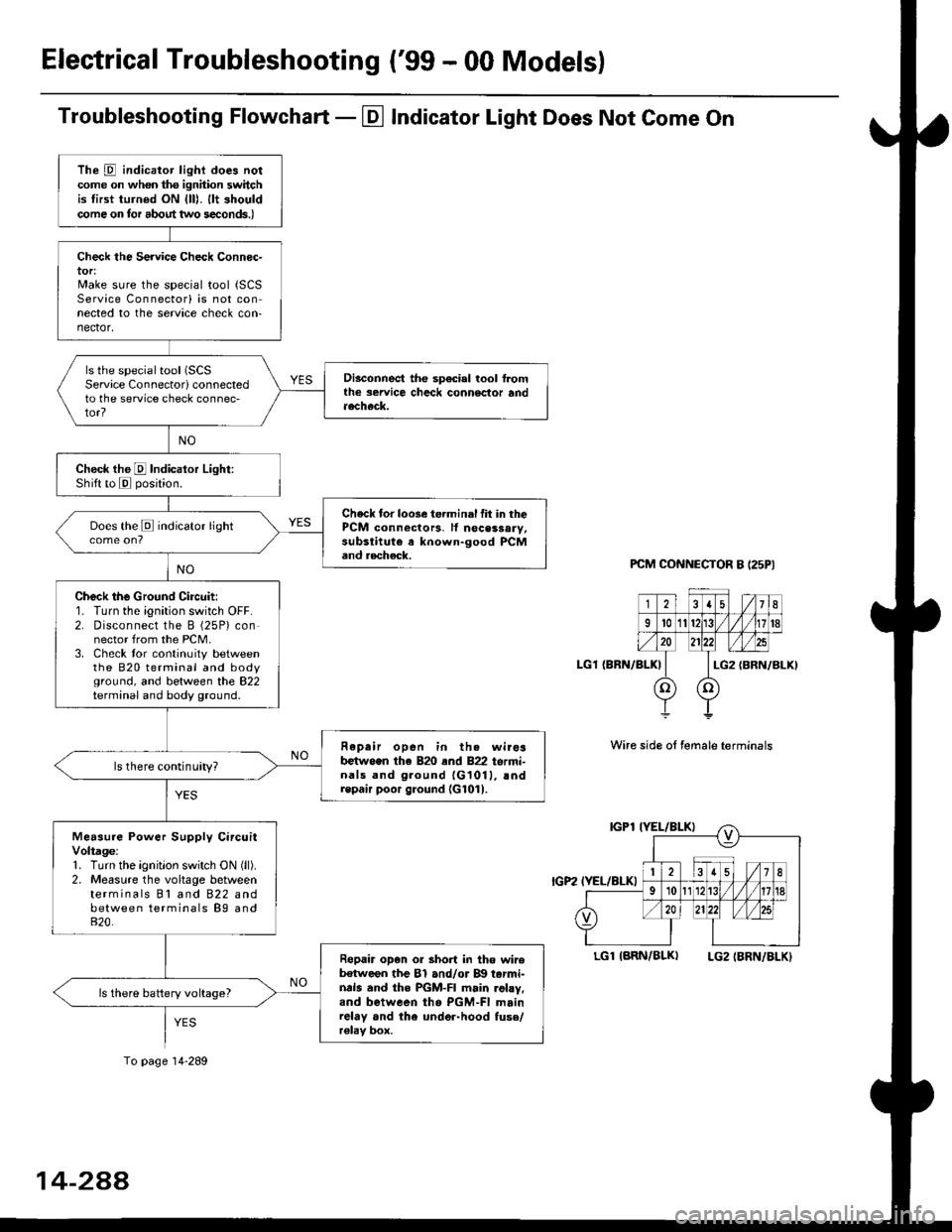
Troubleshooting Flowchart - El Indicator Light Does Not Come On
PCM CONNECTOR B I25PI
LGl {BRN/BLK)
Wire side ot female terminals
LGlIARN/BLK) LG2IBRN/BLKI
The D indicator light does notcome on whon ths ignhion switchis tirst turned ON {lll. llt shouldcome on tor about two s€conds.)
Check the Service Check Connec-tor:Make sure the special tool {SCSService Connectorl is not connected to the service check con-nector,
ls the special tool (SCS
Service Connectorl connectedto the service check connec-tor?
Disconnect the sp€cial tool f]omthe seruice chcck connoclor andaecheck.
Check the E Indicalor Light:Shift to E posjtion.
Check tor loose te.minal fit in thePCM connectors, lf nocessary,substitute a known-good PCMand aecheck.
Does the E indicator light
Check the Ground Circuit:1. Turn the ignition switch OFF.2. Disconnect the B (25P) connector from the PCM.3. Check tor continuity betweenthe 820 terminal and bodyground, and between the 822terminal and body ground.
Fepair open in th. wirosb€tw.en the 820 end 822 termi-nals and ground {G1011, !ndrepair poor ground {G1011.
ls there continuity?
Measure Power Supply CircuitVoltage:1. Turn the ignitlon switch ON (ll).
2. Measure the voltage betweenterminals Bl and 822 andbetween terminals B9 and820.
Ropair op€n or short in tho wireb€tween the Bl and/or B!| tarmi-nds and the PGM-FI main .ohy,and between tho PGM-FI mainrelay and the under-hood fuso/r€lav box.
ls there battery voltage?
To page 14-289
14-2AA