Page 807 of 2189

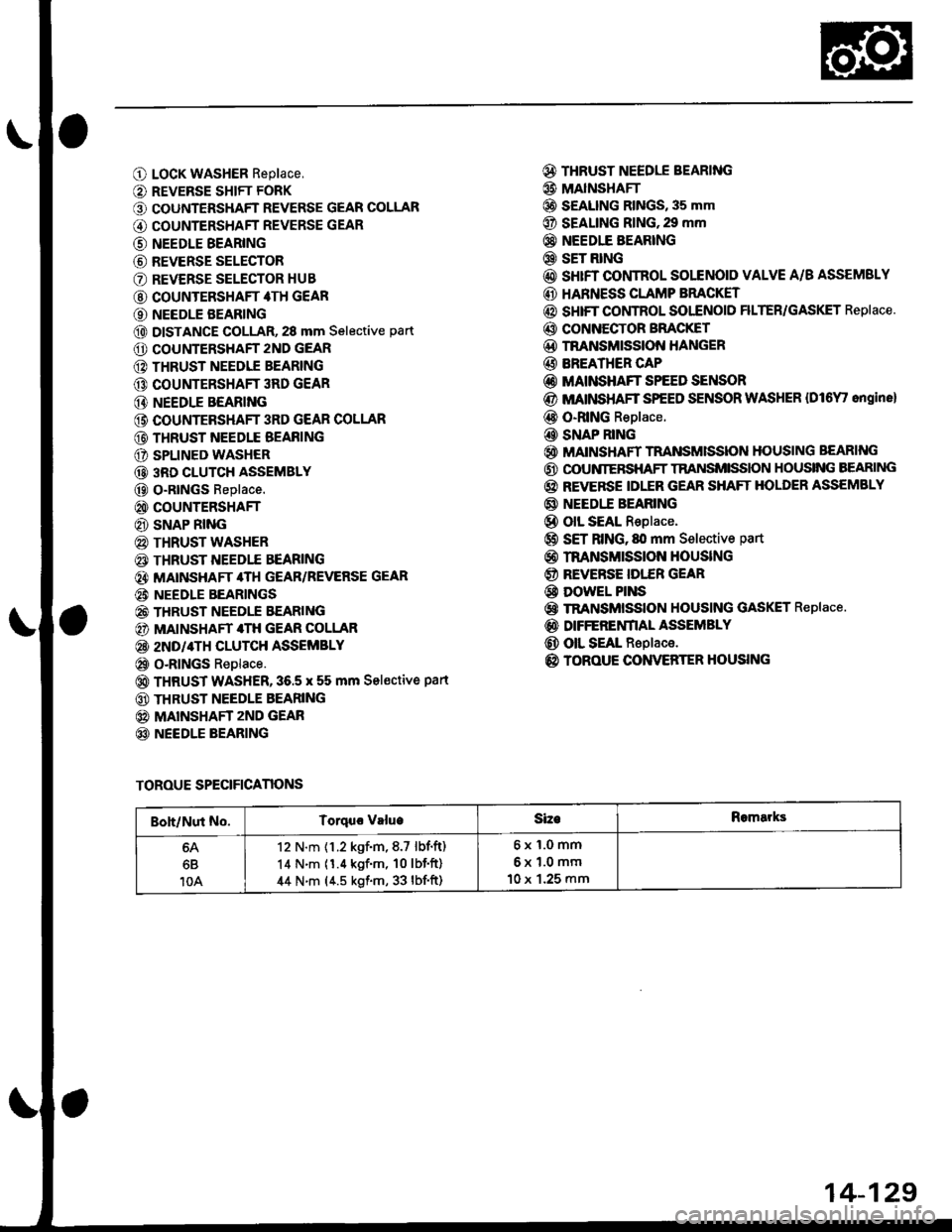
O LocK WASHER Replace,
O REVERSE SHIFT FORK
O COUNTERSHAFT REVERSE GEAR COLLAR
G) COUNTERSHAFT REVERSE GEAR
@ NEEDLE BEARING
@ REVERSE SELECTOR
O REVERSE SELECTOR HUB
@ COUNTERSHAFT 4TH GEAR
O NEEDLE BEARING
@ DISTANCE GOLLAR, 28 mm Selective part
O COUNTERSHAFT 2ND GEAR
@ THRUST NEEDIE BEARING
@ COUNTERSHAFT 3RD GEAR
@ NEEDLE BEARING
@ COUNTEBSHAFT 3RD GEAR COLLAR
@ THRUST NEEDLE BEAFING
O SPLINED WASHER
@ 3RD CLUTCH ASSEMBLY
@ O-RtNGs Replace.
@ COUNTERSHAFT
@ SNAP RING
@ THRUST WASHER
€) THRUST NEEDTE BEARING
@} MATNSHAFT 4TH GEAR/REVERSE GEAR
@i NEEDLE BEARINGS
@ THRUST NEEDLE EEARING
@) MAINSHAFT 4TH GEAR COLLAR
@ 2ND/4TH CLUTCH ASSEMBLY
@ o-RlNGs Replace.
@ THRUST WASHER,36.5 x 55 mm Sel€ctive part
@ THRUST NEEDLE BEARING
@ MAINSHAFT zND GEAR
@ NEEDLE BEARING
@ THRUST NEEDLE BEARING
@ MAINSHAFI
@ S€ALING RINGS, 35 mm
@ SEALING RING,29 mm
@} NEEDIE BEARING
@ SET RING
@ sHrFT CONTROL SOLENOID VALVE A/B ASSEMSLY
@ HARNESS CLAMP BRACKET
@ SHIFT COI,ITROL SOI"ENOID FILTER/GASKET Replace.
@ CONNECTOR BFACKET
@D TNANSMISSION HANGER
@ BREATHER CAP
@ MAINSHAFT SPEED SENSOR
@ MATNSHAFT SPEED SENSOR WASHER {Dl6Y' ongine}
@ O-RING Replace.
@ SNAP RING
@ MAINSHAFT TRANSMISSION HOUSING BEARING
@ OOUNIERSHAFT TRANSMISSION HOUSING BEARING
@ REVERSE IDLER GEAR SHAFT HOLDER ASSEMBLY
@ NEEDI.E BEARING
@ olL SEAL Replace.
@ SET RING, fll mm Selective part
@ rnANsMrssloN HouslNG
@ REVERSE IDI."ER GEAR
@ DowEL PINS
@ TRANSMISSION HOUSING GASKET Replace.
@ DIFFERENfIAL ASSEMBLY
@ OIL SEAL Replace.
@ TOROUE CONVERTER HOUSING
TOROUE SPECIFICANONS
Boh/Nut No.Torquo valueSizeRomarks
6B
10A
12 N.m {1.2 kgf.m,8.7 lbf.ft)
14 N.m (1.4 kgf'm, 10lbf'ft)
44 N.m (4.5 kgf.m, 33 lbf'ft)
6x1.0mm
6x1.0mm
10 x 1.25 mm
14-129
Page 809 of 2189

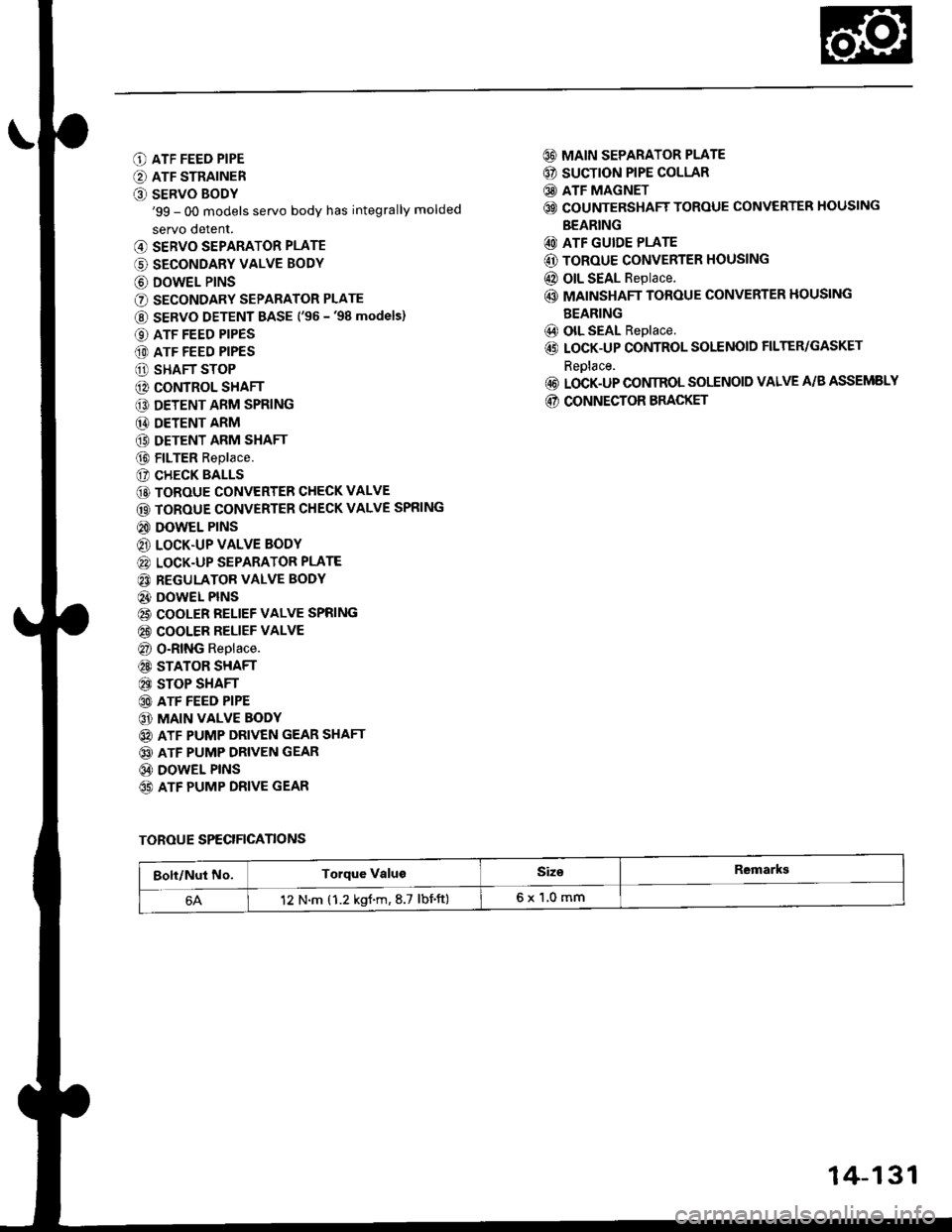
O ATF FEED PIPE
O ATF STRAINER
O SERVO BODY'99 - 00 models servo body has integrally molded
servo detent.
@ SERVO SEPARATOR PLATE
(' SECONDARY VALVE BODY
@ DOWEL P|NS
O SECONDARY SEPARATOR PLATE
@ SERVO DETENT BASE ('�96 -'98 models)
O ATF FEED PIPES
(D ATF FEED PIPES
O SHAFT STOP
@ CONTROL SHAFT
€D DETENT ARM SPRING
@ DETENT ARM
(9 DETENT ARM SHAFT
@ FILTER Replace.
(? CHECK BALLS
@ TOROUE CONVERTER CHECK VALVE
@ TOROUE CONVERTER CHECK VALVE SPRING
@ DOWEL PINS
@ LOCK.UP VALVE BODY
@ LOCK-UP SEPARATOR PLATE
@ REGULATOR VALVE BODY
@} DOWEL PINS
@ COOLER RELIEF VALVE SPRING
@ COOLER RELIEF VALVE
@ O-RING Replace.
@ STATOR SHAFT
@ STOP SHAFT
@ ATF FEED PIPE
@ MAIN VALVE BODY
@ ATF PUMP DRIVEN GEAR SHAFT
@ ATF PUMP DRIVEN GEAR
@ DOWEL PINS
65) ATF PUMP DRIVE GEAR
@ MAIN SEPARATOR PLATE
@ SUCTION PIPE COLLAR
@ ATF MAGNET
@ COUNTERSHAFT TOROUE CONVERTER HOUSING
BEARING
@ ATF GUIDE PLATE
@ ToRoUE CONVERTER HOUSING
@ OIL SEAL Replace.
@ MAINSHAFT TOROUE CONVERTER HOUSING
BEARING
@) olL SEAL Replace.
@ LOCK-UP CONTROL SOLENOID FILTER/GASKET
Reolace.
@ LOCK-UP CONIROL SOLENOID VALVE A/B ASSEMELY
@ CONNECTOR BRACKET
TOROUE SPECIFICANONS
Bolt/Nut No.Torque ValugSiz€Remarkg
12 N.m (1.2 kgf.m,8.7 lbnft)6x1,0mm
14-131
Page 816 of 2189

Valve Caps
Description
Caps with one projected tip and one flat end are
installed with the flat end toward the inside of the
valve body.
Caps with a projected tip on each end are installed
with the smaller tip toward the inside of the valve
body. The small tip is a spring guide.
Toward outside of valvo body.
Toward insido ot valvo body.
Caps with one projected tip and hollow end are
installed with the tip toward the inside of the valve
body. The tip is a spring guide.
Towa.d outside o, valv6 bodv.
I
14-138
Toward insid€ of valv6 bodv.
Caps with hollow ends are installed with the hollow
end away from the inside ofthe valve body.
Caps with notched ends are installed with the notch
toward the inside of the valve body.
Caps with flat ends and a hole through the center are
installed with the smaller hole toward the inside of
the valve bodv.
Toward outsido of valve bodv.
Efla
Toward inlido ot valve bodv,
Caps with flat ends and a groove around the cap are
installed with the grooved side toward the outside of
the valve body.
Toward oulsido of valv6 body.
"-\"h
,A
\za9
Sectional view.
Toward insido ol valvo body.
Page 817 of 2189

Valve Body
2.
Repair
NOTE: This repair is only necessary if one or more of
the valves in a valve body do not slide smoothly in their
bores. You may use this procedure to free the valves in
the valve bodies.
1. Soak a sheet of #600 abrasive paper in ATF for
about 30 minutes.
Carefully tap the valve body so the sticking valve
drops out of its bore.
CAUTION: lt may b€ necessary to use a small
screwdriver to pry the valve free. Be careful not to
scratch the bore whh the screwdriver.
Inspect the valve for any scuff marks. Use the ATF-
soaked #600 paper to polish off any burrs that are
on the valve, then wash the valve in solvent and dry
it with compressed a ir.
Roll up half a sheet of ATF-soaked paper, and insert
it in the valve bore of the sticking valve.
Twist the paper slightly, so that it unrolls and fits the
bore tightly, then polish the bore by twisting the
paper as you push it in and out.
CAUTION: The valve body is aluminum and doesn't
require much polishing to remove any burrs,
3.
4.
ATF-soaked#600 abrasive Paper
5.
7.
Remove the #600 paper and thoroughly wash the
entire valve body in solvent. then dry it with com-
pressed air.
Coat the valve with ATF, then drop ir into its bore.
It should drop to the bonom of the bore under its
own weight. lf not, repeat step 4, then retest.
VALVE BODY
Remove the valve. then thoroughly clean it and the
valve body with solvent. Dry all parts with com-
pressed air. then reassemble using ATF as a lubri
cant.
W
-M
14-139
Page 819 of 2189
ATF Pump
Inspection
1. Install the ATF pump gears and ATF pump driven
gear shaft in the main valve body
NOTE:
. Lubricate all parts with ATF during inspection.
. Install the ATF pump driven gear with its grooved
and chamfered side facing up as shown.
MAIN VALVE BODY
ATF PUMP ORIVEN GEAR
Grooved and chamfe.ed side
2. Measure the side clearance of the ATF pump drave
and driven gears.
ATF Pump Gears Side {Radial) Clearance:
Standard (New):
ATF Pump Drive Gear
0.105 - 0.1325 mm {0.004 - 0.q)5 in}
ATF Pump Drivsn Gear
0.035 - 0.0625 mm (0.0014 - 0.0025 inl
MAIN VALVE SOOY
YZ]
o?
ATF PUMPDRIVE GEAR
ATF PUMPDRIVEN GEARInspect teeth for wear and damage
lnspect teeth for wear and damage.
3. Remove the ATF pump driven gear shaft. Measure
the thrust clearance of the ATF pump driven gear-
to-valve bodY.
ATF Pump Drive/Drivon Gear Thrust {Axial} Cloarance:
Standard (Now): 0.03 - 0.05 mm 10'001 - 0.002 inl
Sorvice Limit: 0.07 mm (0.003 in)
1+141
Page 820 of 2189
Main Valve Body
Disassembly/lnspection/Reassembly
NOTE:
. Cleanall parts thoroughly in solvent or carburetor cleaner, and drywith compressed air. Blowoutall passages.. Replace the valve body as an assembly if any pans are worn or damaged.. Check all valves for free movement. lf anyfail toslidefreely, see Valve Body Repairon page,l4-139.. Coat all parts with ATF during assembly.
CAUTION: Do not use a magnet to removs tha check balls; it may magnetizo the balls.
CPB VALVEVALVE CAP CLIP
ORIFICE CONTROL VALVE
BALLS, 8
lST ACCUMULATOR CHOKE
MODULATORVALVE
RELIEF VALVEVALVE
MAIN VALVE EODYInspect for wear, scratchesand scoring.
SEBVO CONTROL VAL
I.2 SHIFT VALVE
14-142
VALVE CAP
Page 821 of 2189
CHECK BALL
w
MAIN VALVE BODY(Sectional viewl
SPRING SPECIFICATIONS
CHECK BALLS
CHECK BALLS
Unit: mm (in)
No.Springs
Standard (New)
Wire Dia.o.D.Free LengthNo. ot Coils
o
@
@
@
@
@
Relief valve spring
Modulator valve spring
CPB valve spring
1-2 shift valve spring
2nd orifice control valve spring
Servo control valve spring
1.1 (0.043)'1.4 (0.055)
0.9 (0.035)
0.9 (0.035)
0.7 (0.028)
1.0 (0.039)
8.6 (0.342)
9.4 (0.374)
8.1 t0.3221
7.6 {0.302)
6.6 (0.262)
8.'t to.322l
37.1 (1.461)
35.0 (1.378)
47.2 (1.8s8)
41.3 (1.6261
34.8 (1.370)
52.1 t2.O51l
13.4
10.91C ?'15.3
22.0
20.8
1+143
Page 822 of 2189

Secondary Valve Body
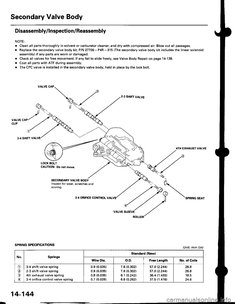
Disassembly/lnspection/Reassembly
NOTE:
. Cleanall parts thoroughly in solvent or carburetor cleaner. and drywith compressed air, Blowoutall passages.
. Replace the secondary valve body kit. P/N 27700 - P4R - 315 (The secondary valve body kit includes the linear solenoid
assembly) if any parts are worn or damaged.
. Checkall valves for free movement. lf anyfailto slide freely, seeValveBody Repairon page 14-139,
. Coat all parts with ATF during assembly.
. The CPC valve is installed in the secondary valve body, held in place by the lock bolt.
2.3 SHIFT VALVE
3.4 SHIFT VAL
.TH EXHAUST VALVE
LOCK BOLTCAUTION: Do not move.
SECONDARY VALVE BODYInspect for wear, scratches 6ndscoring.
3-'l ORIFICE CONTROL VAL
VALVE
SPRING SPECIFICATIONSUnit: mm (in)
No.SpringsStandard {New)
Wire Dia.o.D.Free LongthNo. of Coils
ora,.n
3-4 shift valve spring
2-3 sh ift valve spring
4th exhaust valve spring
3-4 orifice control valve spring
0.910.035)
0.9 {0.035)
0.9 {0.035)
0.7 {0.028)
7.6 (0.302)
7.6 (0.302)
6.1 10.2421
6.6 (0.262)
57 .O 12.2441
57 .O 12.2441
36.4 (1.433)
37.5 (1.476)
26.8
26.8
24.6
14-144