Page 512 of 2189
Intake Air System
\JSystem DescriPtion
The system supp|ies air for a|| engine needs' |t consists of the intake air pipe' Air C|eaner (ACL}, intake air duct, Thrott|e
Body (TB), ldle Air control (lAc) valve and intake manifold. A resonator in the intake air pipe provides additional silencing
as air is drawn into the system.
D16Y5, D16Y8, 816A2 engine {M/Tl
YEL/ - From PGM-FIaLK - MA|N RELAY
BLK/BLU
-- ORN
INTAKEAIRDUCT
IROTARYIIAC VALVE
Iaru
ENGINECOOLANT
BLK/
INTAKEAIR DUCT
I
D16Y5 engine (CVT), D16Y8 engine (A/T)' f'ttlxr ,tla"tpoto
D16Y7 engine:
{ROTARY)IAC VALVE
VARIOUSSENSORS
INTAKEAIRPIPE
tr
RESONATOR
!r,
IAC VALVE
BLK
11-243
Page 691 of 2189
Electronic Control SYstem
The electronac controt system consrsts of a Powertrain control Module (PcM), sensors, a Iinear solenoid and four solenoid
valves, shifting and lock-up are electronically controlled for comfortable driving under all conditions The PCM is located
below the dashboard, under the front lower panel on the passenger's side
PGM-FIControl Sy3tem
A/T Control SYstom
Shift Control
Lock-uD Control
14-13
Page 730 of 2189

Symptom-to-Component Ghart
Electrical System -'gG - 98 Models
*1: The DTC in the parentheses is the code E indicator light indicates when the Data Link connector is connected to theHonda PGM Tester.*2: Whenever the Honda PGM Tester or Scan Tool detects an automatic transmission control system DTC, p07OO will beset in the PGM-FI control svstem.
DTCIIE Indicaior
LightMILDotection ltemPage
P1753
fl)BlinksONLock-up control solenoid valve A14-56
P1758
\21BlinksONLock-up control solenoid valve B14-58
P1705
(51BlinksONAy'T gear position switch (short to groundl14-60
P1706
(6)OFFONA,/T gear position switch (open)14-62
P0753
l7lBlinksONShift control solenoid valve A14-64
P0758
{8)ElinksONShift control solenoid valve B14-66
POl20
(9)BlinksONCountershaft speed sensor14-68
P0715
{15)
'96 - 97
models:
OFF'98 model:
Blinks
ON
Mainshaft speed sensor
14-70
P1768
{16)BlinksONLinear solenoid't 4-72
P0740
(40)OFFONLock-up control system14-7 4
P0730
(41)OFFONShift control system14-75
P0700*,
(none)Automatic transmission control svstem in the pGM-Fl
control svstem
14-52
Page 732 of 2189

Symptom-to-Component Chart
Electrical System -'99 - 00 Models
*1: The DTc in the parentheses is the code E indicator tight indicates when the Data Link connector is connected to theHonda PGM Tester.*2: Whenever the Honda PGM Tester or scan Tool detects an automatic transmission control system DTc, p07oo will beset in the PGM-FI control svstem
DTC*IE Indicator
LightMILDotostion ltemPage
P1753
fi)BlinksONLock-up control solenoid valve A'14-80
P1758
t2lBlinksONLock-up control solenoid valve B14-82
P1705
{5}BlinksONAy'T gear position switch {short to ground)14-84
P1706
(6)OFFONy'VT gear position switch {open)14-81
P0753
\71BlinksONShift control solenoid valve A14-89
P0758
(8)BlinksONShift control solenoid valve B14-9r
P0720
(9)BlinksONCountershaft speed sensorr4-93
P0715
(15)B linksONMainshaft speed sensor14-95
P1768
(16)BlinksONLinear solenoid't 4-97
PO7 40(40)OFFONLock-up control system14-99
P0730
(41)OFFONShift control svstem14- 100
P0700*,
(none)OFFAutomatic transmission control system in the pGM_Fl
controt svstem
14-54
Page 780 of 2189

Electrical Troubleshooting ('99 - 00 Models)
Troubleshooting Flowchart - E Indicator Light Does Not Come On
FCM CONNECTOR B (25P}
LGl {8RN/ALKI{BRN/8LK}
Wire side ol temale terminals
LGl IBNN/BLK} LG2 {BRN/BLK)
i2t5 6q
910t7
LG2
o) (o
The Pll indicator light does notcome on when the ignitionswitch is fi.st turned ON (ll). lltshould come on for about twoseconda.l
Check the Service Check Con-nector:Make sure the special tool (SCS
Service Connector) is not connect-ed to the service check connector?
ls the specialtool {SCS ServiceConnector) is not connected tothe seNice check connector.
Disconnect the special tool fromthe service check connector andr6check.
Check the Dll lndicator LightiShift to d position.
Check for loose terminal fit in thePCM connecto13. It necessary.sub3titute a known-good PCMand recheck.
Does the @ indicator lightcome on?
Check the Ground Circuit:1. Turn the ignition switch OFF.2. Disconnect the B (25P) con-nector from the PCM.3. Check for continuity betweenthe 820 terminal and bodyground, and between the 822terminal and body ground.
Repair open in the wiresbetween the B20 rnd 822 termi-nals and ground (G101), andrep.ir poor ground (G1011.
Measure Power Supply CircuitVoltage:1. Turn the ignition switch ON {ll}.2. Measure the voltage betweenterminals B1 and 822 andbetween terminals Bg and820.
Repair open or short in the wi.obetween th6 81 and/or 89 termi-nals and the PGM-FI main relav,and between th€ PGM-FI mainr€ley rnd the under-hood tus€/relay box.
To page 14''103
14-102
Page 911 of 2189

Troubleshooting Procedures
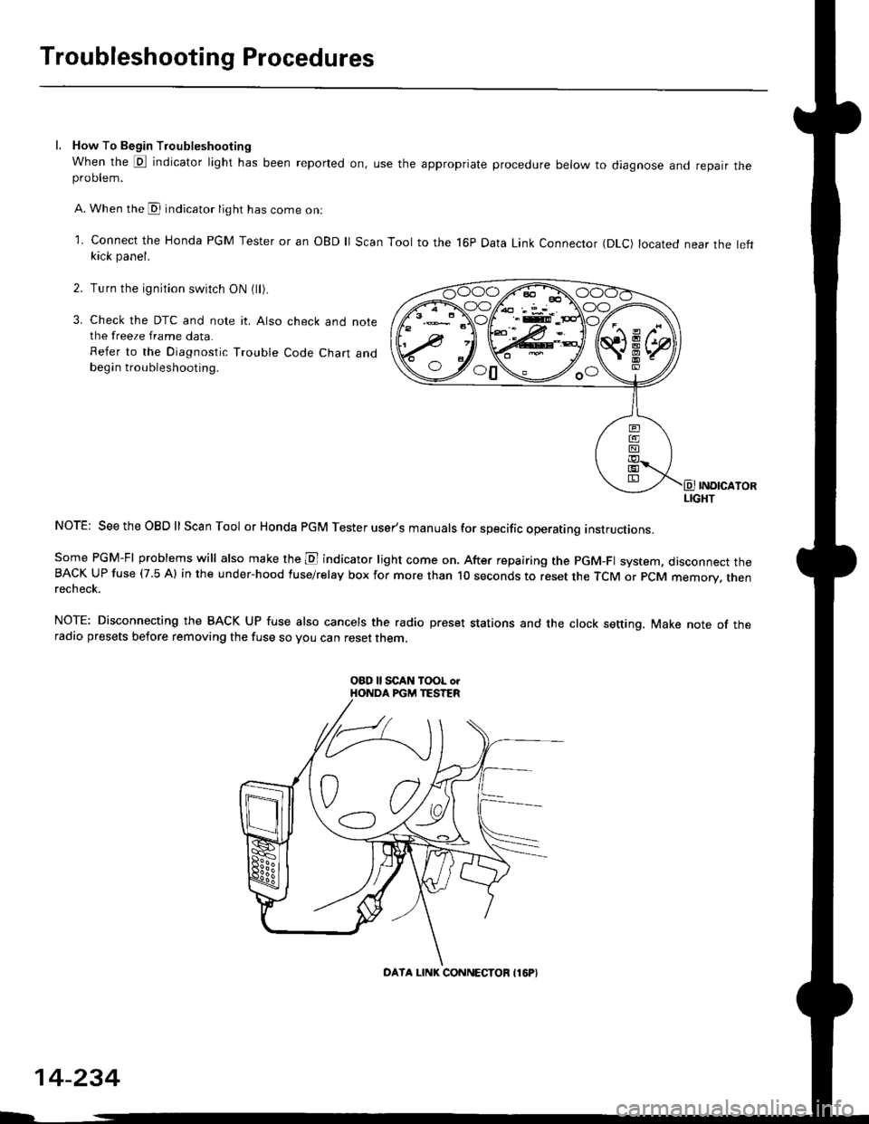
l. How To Begin Troubleshooting
When the E indicator light has been reported on, use the appropriate procedure below to diagnose and repatr theproDlem.
A. When the @ indicator light has come on:
l connect the Honda PGM Tester or an oBD ll Scan Tool to the 16P Data Link Connector (DLc) located near the leftkick panel.
Turn the ignition switch ON (ll).
Check the DTC and note it. Also check and notethe freeze frame data.
Refer to the Diagnostic Trouble Code Chart andbegin troubleshooting.
INOICATORLIGHT
NOTE: SeetheOBDll Scan Tool or Honda PGM Tester user's manuals for specific operating instructions.
Some PGM-FI problems will also make the E indicator light come on. After repairing the pGM-Fl system, disconnect theBACK UP fuse (7.5 Al in the under-hood fuse/relay box for more than l0 seconds to reset the TCM or PCM memory, rnenrecheck.
NOTE: Disconnecting the BACK UP fuse also cancels the radio preset stations and the clock setting. Make note of theradio presets before removing the fuse so you can reset them,
2.
3.
o0\e--loo
OATA LINK CONNECTOB I16P}
14-234
Page 912 of 2189

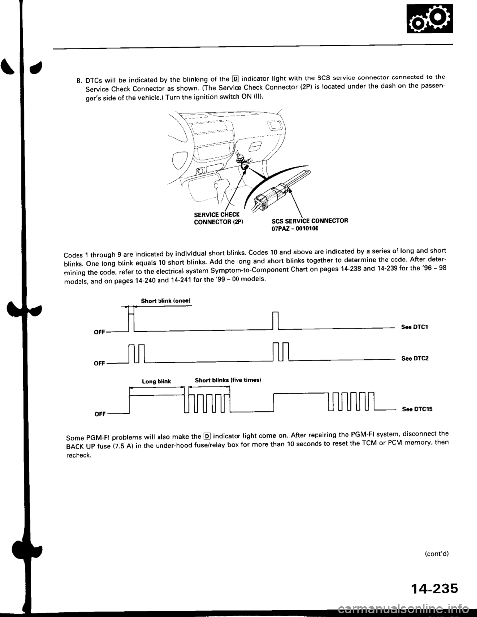
B. DTCS will be indicated by the blinking of the E indicator light with the SCS service connector connected to the
Service Check Connector as shown. (The Service Check Connector (2P) is located under the dash on the passen
ger's side of the vehicle.) Turn the ignition switch ON (ll).
CONNECTOR07PAZ - 00101(x)
codes 1 through 9 are indicated by individual shon btinks. codes 10 and above are indicated by a series of long and short
b|inks.one|ongblinkequa|sloshortb|inks.Addthe|ongandshortb|inkstogethertodeterminethecode.Afterdeter
miningthecode,refertothee|ectrica|systemsymptom-to-componentchartonpagesl4-238and14.239forthe,96_98
models, and on pages 14-240 and 14'241 for the '99 - 00 models
Soc DTCI
Sor DTC2
Long blinkShort blinks |tive tim€sl
some pGM-Ft problems wi
atso make the E indicator light come on. After repairing the PGM-FI system, disconnect the
BACKUPfuse(7.5A)intheUnder.hoodfuse/re|ayboxformorethanl0secondstoresettheTcMorPcMmemory,then
recheck.
Scc DTCI5
(cont'd)
14-235
iii:j
,,,/
CONNECTOR {2PI
Shorl blink (oncc)
Page 919 of 2189

Electrical Troubleshooting ('96 - 98 Modelsl
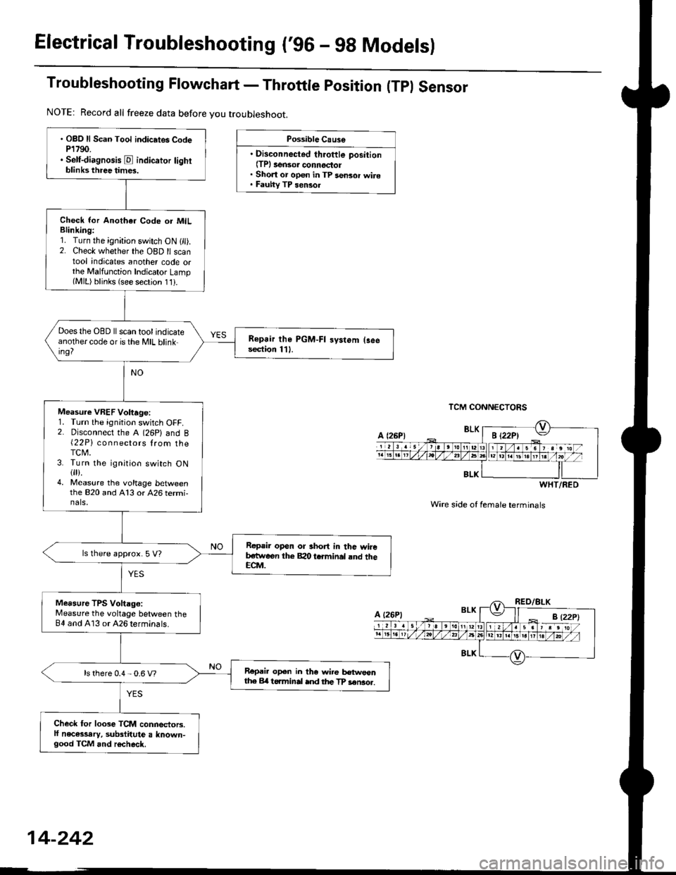
Troubleshooting Flowchart - Throttle position (Tpl Sensor
Possible Cause
. Disconnected throftle position(TPl 3ensor connoctol. Short or open in TP sensor wire. Fauhy TP sensol
TCM CONNECTORS
Wire s;de of female terminals
. OBO ll Scan Tool indic.tes CodeP1790.. Self-diagnosis E indicator lightblinks three times.
Check lor Anothar Code or MILBlinking:1. Turn the ignition switch ON 1 ).2. Check whether the OBD ll scantool indicates another code orthe Malfunction Indicator Lamp(MlL) blinks (see secrion 11).
Does the OBD ll scan tool indicateanothercode oristhe MIL blink-ing?
Repair the PGM-FI systom (3eesection 111.
Measure VREF Voltage:1. Turn the ignition switch OFF.2. Disconnect the A (26P) and B{22P} connectors lrom theTCM.3. Turn the ignition switch ON{fl).4. Measure the voltage bet\iveenthe 820 and A13 or 426 termi-nals,
Repair open or short in thc wireb,stween the Bao tcrminal rnd theECM.
ls lhere approx. 5 V?
Measure TPS Voltago:Measure the voltage between theB4 and A13 or 426 terminals.
Repail open in the wire tr€tweonthe Erl t6.minal ind the TP sen3o..ls there 0.4 - 0.6 V?
Check for loose TCM connectors.lf necessary, substitute a known-good TCM and r6check.
NOTE: Record all freeze data before you troubleshoot.
BLK
WHT/RED
A {26P1