Page 1969 of 2189
Brake System Indicator Light (cont'd)
- How the Circuit Works
The brake system indicator light comes on to alert
the driver that the parking brake is applied, or that
the brake fluid level is low. lt also comes on as a
bulb test when the engine is cranked.
Parking Brake
With the ignition switch in ON (ll) or START (lll),
voltage is applied through fuse 25 to the brake
system light. When you apply the parking brake, the
switch closes and provides a ground for the light.
The light then comes on to remind you that the
parking brake is applied.
Brake Fluid Level
With the ignition switch in ON (ll) or START (lll),
voltage is applied through fuse 25 to the brake
system light. lf the brake fluid level is low, the brake
fluid level switch closes, providing ground to the
circuit. The brake system light then comes on,
alerting the d verto a low brake fluid level in the
brake master cylinder. (Check brake pad wear
before you add fluid).
Bulb Check
With the ignition switch in START (lll) and clutch
pedal depressed or A'lT gear selector in PARK (P)
or NEUTRAL (N), voltage is applied through fuse 31
to the brake bulb check circuit. The brake bulb
check circuit closes, allowing current to flow through
the brake system light and bulb check circuit to
ground. The brake system light then comes on to
test the bulb.
Refer to the Service Manual (Section 23, Electrical)
for specific tests or troubleshooting procedures.
71-2
a
\fa
Page 1990 of 2189
100-2
Headlight Switch (cont'd)
-.I UNDER.DASHRom UderdashFur€/Bslay 8ox orprevrous prge.
- - -ri-Y c421 13 Y C5s1'- ll PHoro 63 ll esoro6J
neoialx I u/EW 50 BEDelfi i v'Edu7
'f ---- Hatchback l, Coupe and Sedan
c2o1 : I !'--'l Itlt5i:^- :i"'oYizt i i Iri"Je'tl
i l3pfif.l-"o."-i ".o,".*l =,a,e.Fema,e, ll L--J pe6161ja , ll terminals reversed
: tr_ _ _ _ _ _ _ _ _ _Y::_ _ _ _ _:
c202PNO|O 23ytEw 1
LEFTBRAKELIGHT/TAILLIGHTPage 110-5
9('99100 models 18)
FED/BLK
RIGHTTAILLIGHTPage 110-5
c562 .
vtEw42
c605
wEw a
RIGHTBRAKELIGHT/TAILLIGHTPage 110-5
LEFTLICENSEPLATELIGHTPage ! 10-5
for '99-'00 models
FUSE/RELAYBOX
1(cruise 3)c604 5
FEO/BLK
"ao,"a* |
I
/---lI \---t
LEFTTAILLIGHTPage 110-5
\;,,
LEFT FRONTPARKING/TURNSIGNALLIGHTPage 110-2
RIGHTLICENSEPLATELIGHTPage 110-5
,rUrOO ro.",. ?, I
r-\\_,
".,"-[TI
RIGHT FRONTPARKING/TURN SIGNALLIGHTPage 1l0-2
Page 1996 of 2189
License Lights, Parking Lights, and Taillights (cont'd)
From page 110-2.
CBtl^lvl{t
3
- '99-'00 Sedans
c562
vtEw 42
FEO/BLK
18(GX 5)
REO/BLK
See BrakeLights
RIGHTBRAKELIGHT/OUTERTAILLIGHT
RIGHTLICENSEPLATELIGHT
1l
@
zY
LEFTLICENSEPLATELIGHT
1l
@
zY
LEFTBRAKELIGHT/OUTERTAIL.LIGHT
RIGHTINNEBTAILLIGHT
LEFTINNERTAILLIGHT
2^
@
rY
2A
@rY
110-4
Page 2005 of 2189
- Canada\
-- f Pdoto\i3 A vttw.rsUNDER.DASHFUSE/RELAYBOX
DAYTIMERUNNINGLIGHTSCONTROLUNITvtEw 66
FUSE 2!(EUXMtIG7.5A
c420
vtEw 53
sE 20xM G Uclfr)
r'
I
I
IF
r
16
BIKWHT
See BrakeSystemIndicator Light
lcnvneo I
asl
-il*'*
IY
L_-J+: G401PHOTO 57
-
A4
B1
\BED/GRN
OAYTIMERUNNINGLIGHTSRESISTOR
S€e GroundDlstribution,page 1,1-6.PARKINGBRAKEswtTcHClosed withparking brakeapplied.H
Ughis-on Satterynpur
Hoadl8hi cornrol
lgnition
b'rak8 inputGround
Brake sysiemindicator lightcontrol
FUSE ra$r,rlxlxs ucl|l R€laY)7.ta
110-13
\
Page 2006 of 2189
Headlights (cont'd)
- How the Circuit Works
Low Beams
With the headlight switch in HEAD and the dimmer
switch in LO, current tlows through the headlight
switch. fuse 21 . fuse 22. and the low beam
tilaments to ground, and the low beams come on.
High Beams
With the headlight switch in HEAD and the dimmer
switch in Hl, current flows through the headlight
switch, dimmer switch, fuses 4, 5, and the high
beam filaments to ground, and the high beams
come on.
Current also llows through the high beam indicator
light to ground. The high beam indicator comes on
to remind the driver that the high beams are on.
Flash-to-Pass
The flash feature works with the headlight switch in
OFF, PARK, or HEAD (low beams). When you move
the flash-to-pass switch to ON, current flows
through the switch, fuses 4 and 5, and the high
beam filaments to ground, and the high beams
flash. The high beam indicator also flashes during
the flash operation. The flash function has no effect
if the high beams are already on
Daytime Running Lights (Canada)
When you turn the ignition to ON (ll) with the
parking brake released, the daytime running lights
control unit supplies battery voltage at the
WHT/RED wire. This voltage is applied to the high
beam headlights through the daytime running lights
resistor. Each high beam headlight receives less
than battery voltage causing them to come on at
reduced brightness.
lf the parking brake is set, a ground signal is applied
to the daytime running lights control unit at the
RED/GRN wire. lf the parking brake is set when you
first turn the ignition switch to ON (ll), the high beam
headlights will remain off until you release the
parking brake. Once the high beam headlights are
on, setting the parking brake will not turn them ofi.
When low or high beam operation is requested,
battery voltage from the headlight switch is applied
to the daytime running light control unit via the RED
wire. The daytime running lights control unit then
turns off the headlights.
Refer to the Service Manual (Section 23, Electrical)
for specific tests or lroubleshootrng procedures.
110-14
Page 2130 of 2189
65. Combination Wiper Switch
- Right side ot steering column
Connector A
- Natural- On main wire harness
1BLU (Windshield wipermotor LOW conkol)
BLU/YEL(Windshield wipermotor HIGH control)
YEUBLU (lntermittentwiper ON input)
lilale - GRNFemale - LT GRN(Rear window wipermotor conkol)
lrale - LT GRNFema|e _ LT GRN/BLK(Rear window wipermotor control)
4 GnN/BLK (Fuse 26)
5 BLK (G401)
7 BLU/BLK(lntermittenvpark wiper control)
8 WHT/BLK (Windshieldwasher motor)
BLK (G401)
Male - WHTFemale - GRN (Fuse 3)
Male - BLUF€male _ GRN/BLK(Rear window washermotor control)
\
Connector B (C4271 (with Rear Wiper)
- White- On main wire harness
3
5
6
)
I3
68
13
4
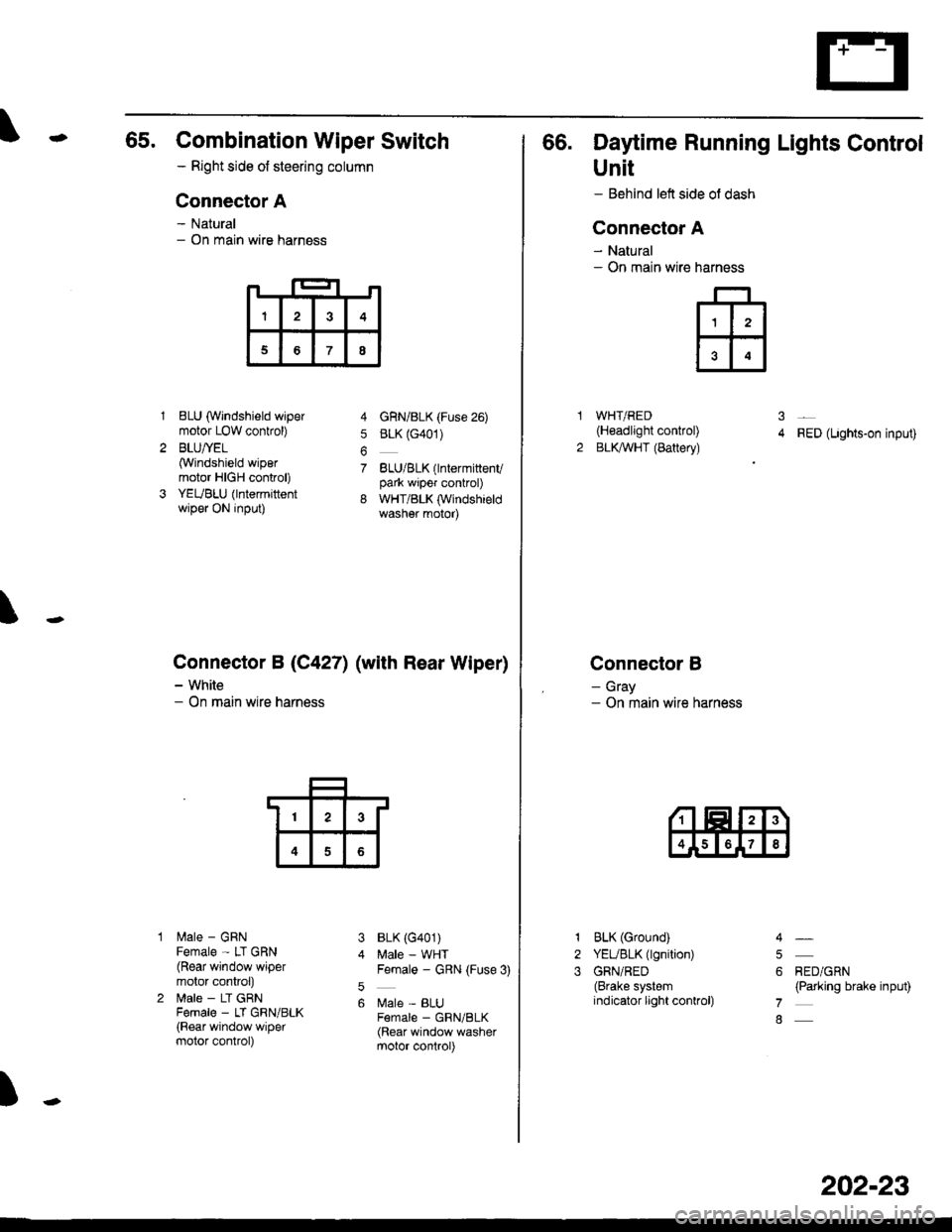
66. Daytime Running Lights Control
Unit
- Behind left side ol dash
Connector A
- Natural- On main wire
WHT/RED(H€adlight control)
BLKAVHT (Battery)RED (Lights-on input)
Connector B
- Gray- On main wire harness
narness
ffi
31
2
1
2
3
BLK (Ground)
YEUBLK (lgnition)
GRN/RED(Brake systemindicator light conkol)
RED/GRN(Parking brake input)
4
5
6
7
8
202-23
Page 2169 of 2189
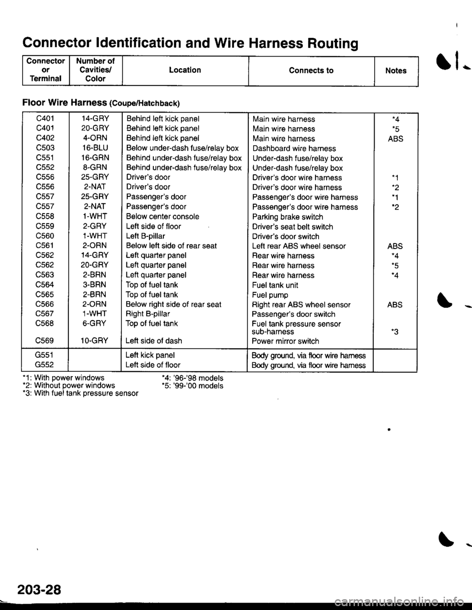
Connector ldentification and Wire Harness Routing
Connector
or
Terminal
Number ot
Cavities/
Color
LocationConnects toNotesll-
Floor Wire Harness (Coupe/Hatchback)
c401
c401
c402
c503
v)az
ucco
ucc/
trcc/
u556
uccv
UCOU
c561
u30z
UCOZ
UCOJ
c564
u5b5
ucoo
uco/
trco.'
vcov
14.GRY
2O-GRY
4-ORN
16-BLU
16.GRN
8-GRN
25-GRY
2-NAT
25-GRY
2-NAT
1-WHT
2-GRY
1-WHT
2.ORN
14-GRY
2O-GRY
2-BRN
3.BRN
2.BRN
2-ORN
1-WHT
6-GRY
1O-GRY
Behind left kick panel
Behind left kick panel
Behind left kick panel
Below under-dash fuse/relay box
Behind under-dash fuse/relay box
Behind under-dash fuse/relay box
Driveas door
Driver's door
Passenger's door
Passenger's door
Below center console
Lett side of floor
Left B-pillar
Below left side of rear seat
Left quarter panel
Left quarter panel
Left quarter panel
Top of fuel tank
Top of fuel tank
Below right side of rear seat
Right B-pillar
Top ot fuel tank
Left side of dash
Main wire harness
Main wire harness
Main wire harness
Dashboard wire harness
Underdash fuse/relay box
Under-dash fuse/relay box
Driver's door wire harness
Drivefs door wire harness
Passenger's door wire harness
Passenger's door wire harness
Parking brake switch
Driver's seat belt switch
Driver's door switch
Left rear ABS wheel sensor
Rear wire harness
Rear wire harness
Rear wire harness
Fuel tank unit
Fuel pump
Right rear ABS wheel sensor
Passenger's door switch
Fuel tank pressure sensor
sub-harness
Power mirror switch
"1
'1
'2
"5
ABS
AEIJ'4
'5
'tI'D
-3
G552
Left kick panel
Left side of tloor
Body ground. via floor wire hamess
Body ground, via floor wire hamess
-1: With power windows "4: '96-98 models.2: Without oower windows .5: '99-'00 models.3: With fuel tank oressure sensor
203-28
Page 2171 of 2189
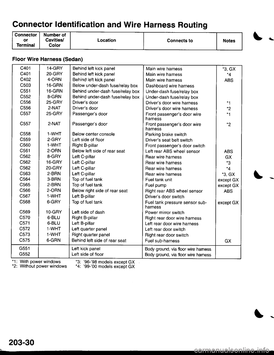
Connector ldentification and Wire Harness Routing
Connector
ol
Terminal
Number of
Cavities/
Color
LocationConnects toNotes\
Floor Wire Harness (Sedan)
c401
c401
c402
c503
c551
trccz
vcco
ucc/
\,CC/
u55b
UCDY
UCOU
c561
lJcoz
ucoz
UCOZ
1'-coJ
lJ50.t
ucoc
ucoo
uco/
ucoo
c569
c570
c571
wJt z
TJC/J
v3/c
14-GRY
2O-GRY
4.ORN
16-GRN
16-GRN
8-GRN
25-GRY
2-NAT
25-GRY
2-NAT
1-WHT
2.GRY
1-WHT
2-ORN
8-GRY
16.GRY
20-GRY
2-BRN
3.BRN
2-BRN
2-OBN
1-WHT
6-GRY
1O-GRY
6-BLU
6.BLU'1-WHT
1.WHT
6-GRN
Behind left kick panel
Behind left kick panel
Behind left kick panel
Below under-dash fuse/relay box
Behind under-dash fuse/relay box
Behind under-dash fuse/relay box
Driver's door
Driver's door
Passenger's door
Passengels door
Below center console
Left side of floor
Right B-pillar
Below left side of rear seat
Left C-pillar
Left C-pillar
Left C-pillar
Left C-pillar
Top of fuel tank
Top ol fuel tank
Below right side of rear seat
Left B-pillar
Top of tuel tank
Left side of dash
Right B-pillar
Left B-pillar
Left quarter panel
Right quarter panel
Behind left side of rear seat
Main wire harness
Main wire harness
Main wire harness
Dashboard wire harness
Under-dash fuse/relay box
Under-dash fuse/relay box
Driver's door wire harness
Driver's door wire harness
Front passengeas door wireharness
Front passenger's door wireharness
Parking brake switch
Driver's seat belt switch
Front passenger's door switch
Left rear ABS wheel sensor
Rear wire harness
Rear wire harness
Rear wire harness
Bear wire harness
Fuel tank unit
Fuel pump
Right rear ABS wheel sensor
Driver's door switch
Fuel tank pressure sensor sub-harness
Power mirror switch
Right rear door wire harness
Lett rear door wire harness
Left rear door switch
Right rear door switch
Fuel sub-harness
-3, GX"4
ABS
"1
'1
ABS
GX
o
-3, GX
except GX
except GX
ABS
except GX
GX
G551
tftcz
Left kick panel
Left side of floor
Body ground, via floor wire hamess
Body ground, via floor wire hamess
.1 : With power windows -3: '96-'98 models except GX.2: Without power windows .4: '99-'00 models except GX
203-30