2000 HONDA CIVIC Section 23
[x] Cancel search: Section 23Page 491 of 2189
ldle Control System
ldle Speed Setting (cont'dl
Inspeqtion/Adiustment
38 D16Y5 engine whh M/T,'99 - 00 81642 engine
NOTE: Before setting the idle speed, check the follow-ing items;- The MIL has not been reported on.- lgnition timing- Spark plugs- Air cleaner- PCV system
'1. Start the engine. Hold the engine at 3,000 rpm withno load (transmission in neutral) until the radiatorfan comes on, then let it idle.
Connect a tachometer.
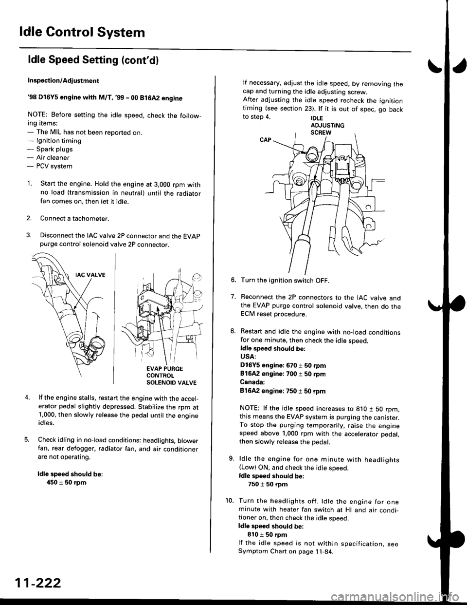
Disconnect the IAC valve 2P connector and the EVAPpurge controlsolenoid valve 2P connector.
EVAP PURGECONTROLSOLENOID VALVE
lf the engine stalls, restart the engine with the accel-erator pedal slightly depressed. Stabilize the rpm at1.000, then slowly release the pedal until the engineidles.
Check idling in no-load conditions: headlights, blowerfan, rear defogger, radiator fan, and air conditionerare not operating.
ldl€ speed should be:
450 i 50 rpm
11-222
lf necessary, adjust the idle speed, by removrng lnecap and turning the idle adjusting screw.After adjusting the idle speed recheck the ignitlontiming (see section 23). lf it is out of spec, go backto step 4. |DLE
6. Turn the ignition switch OFF.
7. Reconnect the 2P connectors to the IAC valve andthe EVAP purge control solenoid valve, then do theECM reset procedure.
8. Restart and idle the engine with no-load conditionsfor one minute, then check the idle sDeed.ldle speed should bo:
USA:
D16Y5 engine: 670 i 50 rpm
81642 engine: 700 i 50 rpm
Canada:
81642 engine: 750 t 50 rpm
NOTE: lf the idle speed increases to 8lO t 50 rpm,this means the EVAP system is purging the canister.To stop the purging temporarily, raise the enginespeed above 1,000 rpm with the accelerator pedal,
then slowly release the pedal.
9. ldle the engine for one minute with headlights(Low) ON. and check the idle speed.
ldle speed should be:
750 i 50 rpm
10. Turn the headlights off. ldle the engine for oneminute with heater fan switch at Hl and air condi-tioner on, then check the idle soeed.ldls speed should be:
810 t 50 rpm
lf the idle speed is not within specification, seeSymptom Chart on page 11-84.
Page 505 of 2189
Fuel Supply System
Fuel Pump
Testing
!@ Do not smoke during the test, Keep open
flame away from your work atea,
lf you suspect a problem with the fuel pump, check that the
fuel pump actually runs; when it is ON (ll), you will hear
some noise if you hold your ear to the fuel fill port with the
fuel fill cap removed. The fuel pump should run for two
seconds when ignition switch is first turned ON (ll). lf the
fuel pump does not make noise, check it as follows:
L Remove the seat cushion {see section 20).
2. Remove the access panel from the floor.
3. Make sure the ignition switch is OFF, then discon-
nect the Iueltank 2P connector.
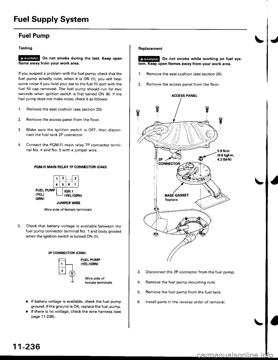
4. Connect the PGM-FI main relay 7P connector termi-
nal No. 4 and No. 5 with a jumper wire.
PGM-R MAIN RELAY 7P CONNECTOR lC4,(|l
FUEL PUMP
IYEL/GRN}
IGN 1(YEL/GRNI
tcs6s)
FUEL PUMP(YEL/GRNI
Wire side oftemale torminals
JUMPER WIRE
Wire side of temale terminals
Check that battery voltage is available between the
fuel pump connector terminal No. 1 and body ground
when the ignition switch is turned ON (ll).
CONNECTOR
=
[t
L3l .i)
T
lf battery voltage is available, check the fuel pump
ground. lf the ground is OK, replace the fuel pump.
lf there is no voltage, check the wire harness (see
page 11-238).
11-236
Replacement
@E Do not smoke while working on tuel svs-
tem. Keep open llames away from your work area.
1. Remove the seat cushion (see section 20).
2. Remove the access panel trom the floor.
3. Disconnect the 2P connector from the fuel pump.
4. Remove the fuel pump mounting nuts.
5. Remove the fuel pump from the fuel tank.
6. Install pans in the reverse order of removal.
ACCESS PANEL
i
Page 510 of 2189
IFuelTank
'96 - 98 models:
Replacement
I
1. Relieve the fuel pressure (see pages \1-230' 23'll'
2. Remove the seat cushion (see section 20).
3. Remove the access panel from the floor'
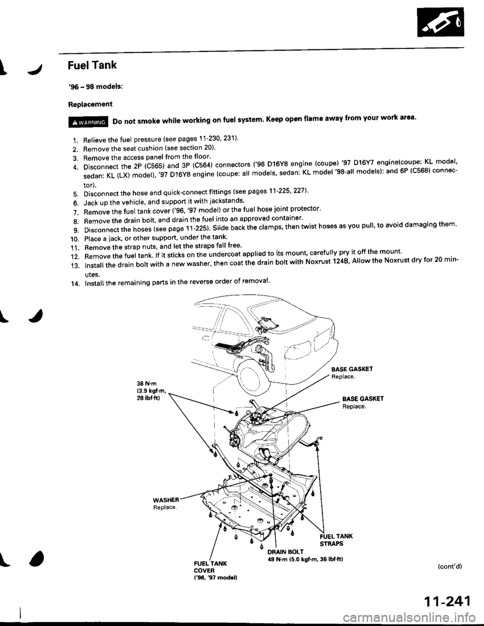
4. Disconnect the 2P (C565) and 3P (C564) connectors ('96 D]6Y8 engine (coupe) '97 D16Y/ engine(coupe: KL model'
sedanKL(LX)model).'97D'l6YSengine(coupe:allmodels'sedan:KLmodel'98-allmodels):and6P(C568)connec-
tor),
5. Disconnect the hose and quick-connect fittings (see pag es'l'l-225' 2271
6. Jack up the vehicle, and support it with jackstands'
7. Removethefuel tank cover ('96,'97 model) orthefuel hose joint protector'
8. Bemovethedrain bolt,and drainthefuel into an approved container'
9. Disconnect the hoses {see page r i-izst. Sria" nu"i ihe clamps, then twist hoses as you pull, to avoid damaging them'
10. Place a jack. or other support, under the tank'
11. Remove the strap nuts, and let the straps fall free'
12. Removethefuel tank lf it sticks on the undercoat applied to its mount' caref u lly pry it off the mount'
13.|nsta||thedrainbo|twithanewwasher.thencoatthedrainbo|twithNoxrustl24B,A||owtheNoxrustdryfor20min-
ules.
14. Installthe remaining pans in the reverse order of removal'
SASE GASKETReplace.
BASE GASKETReplace.
!@@ Do not smoke while working on fuel system' Keep open flame away from your work ar'a'
TANKSTRAPS
DRAIN BOLT,19 N.m {5.0 kgt m, 36 lbf.ftl(cont'd)
11-241
Page 511 of 2189
Fuel Supply System
Fuel Tank {cont'dl
39 - (xt models:
Replac6ment
o
@ Do not smoke whire working on fuer system. Ke€p open frama away trom your work area.
1. Relievethefuel pressure (see pages 11-230,23'll.
2. Remove the seat cushion lsee section 2O).3, Remove the access panel fromthefloor.
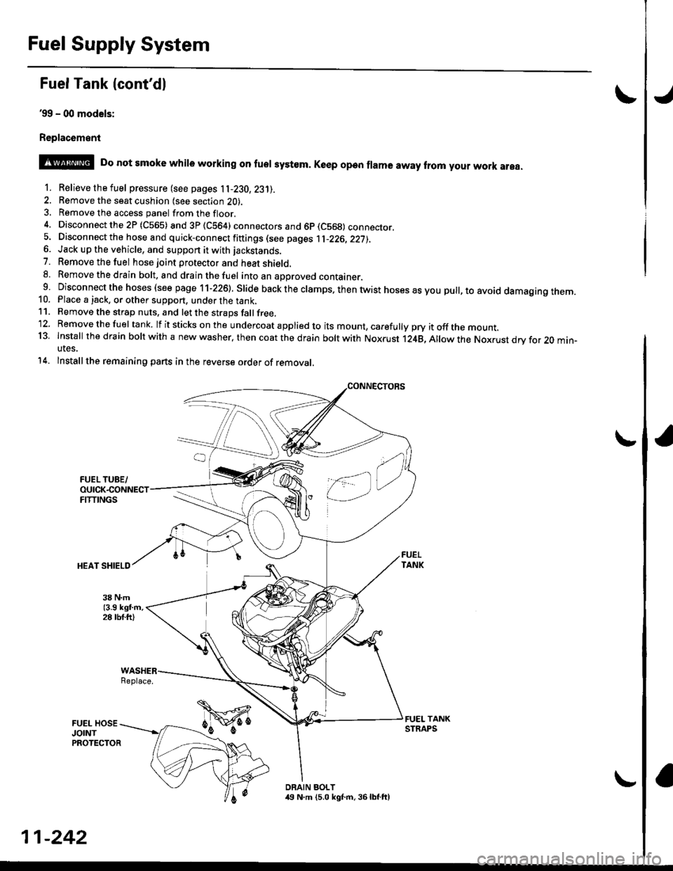
4. Disconnectthe2P (C565) and3P(CS64) connectors and 6p (C569) connecror.5. Disconnect the hose and quick-connect fiftings (see pages 1l-226,22j),6. Jack up the vehicle, and support it with jackstands.
7. Removethefuel hose joint protector and heat shield.8. Removethedrain bolt. and drainthefuel intoan aporoved container.9 Disconnect the hoses (see page 11-226). Slide back the clamps. then twist hoses as you pull, to avoid damagtng rnem.10. Place a jack, or other support, under the tank,11. Remove the strap nuts, and let the straps fallfree,'12. Removethefuel tank. lf itsticks onthe undercoat applied to its mount, carefully pry itoffthe mount.13. Install thedfain boltwith a new washer. then coat the d rain bolt with Noxrust 124B,Allowthe Nox.ust drv for 20 min-utes.
14. Installthe remaining parts in the reverse order of removal,
Replace.
DRAIN BOLT,19 N.m (5.0 kgf.m, 36lbf.ft)
11-242
Page 520 of 2189
\J
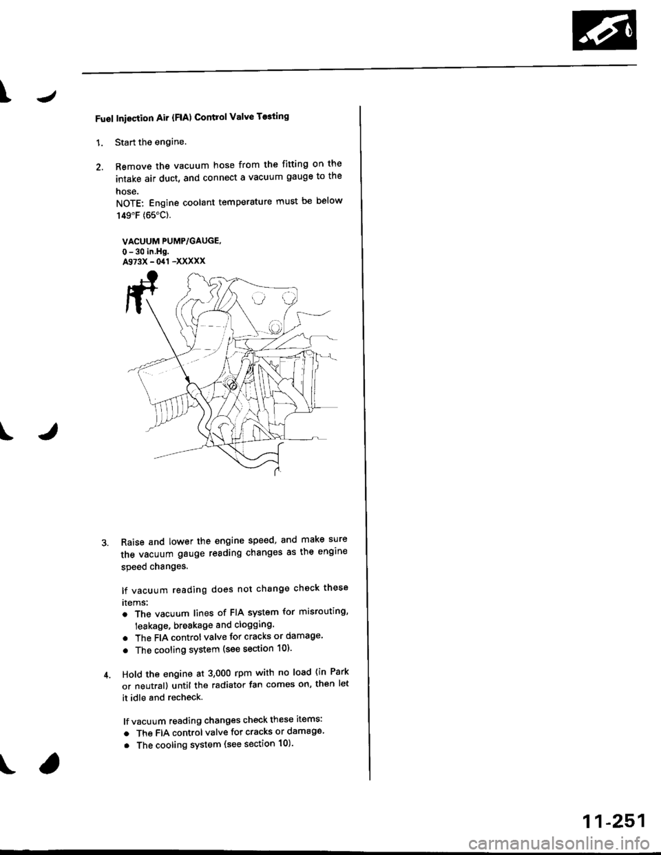
Fuol Iniection Air {FlA) Contlol Valve T$ting
1. Start the engine.
2. Remove the vacuum hose from the fitting on the
intake air duct, and connect a vacuum gauge to the
nose.
NOTE: Engine coolant temperature must be below
149"F (65"C).
VACUUM PUMP/GAUGE,
0-30 in.Hg.A973X - 041 -XXXXX
Raise and lower the engine speed, and make sure
the vacuum gauge reading changes as the engine
speed changes.
lf vacuum reading does not change check these
rtems:
. The vacuum lines of FIA system for misrouting,
leakage, breakage and clogging.
. The FIA controt valve for cracks or damage
. The cooling system (see section 10).
Hold the engine at 3,OOO rpm with no load (in Park
or neutral) until the radiator fan comes on, th€n let
it idle and recheck.
lf vacuum reading changes check these items:
a The FIA control valve for cracks or damage.
. The cooling system (see section 10).
11-251
Page 522 of 2189

\
lTo420l Th" """n toot indicates Diagnostic Troubte code (DTc) p0420: catatyst sysrem efficiency below threshold.
Description
This system evaluates the catalyst's capacity by means of the Ho2s {Primary and secondary) output during stable driving
conditions. ll deterioration has been detected during two consecutive driving cycles. the MIL comes on and DTC P0420 will
be stored.
NOTE: lf some of the DTCS tisted below are stored at the same time as DTC P0420, troubleshoot those DTCS first. then
recheck for DTC P0420
P0137, P0138: Secondary HO2S (Sensor 2)
Po14'1:Secondary H02S {Sensor 2) Heater
Possibl€ Cause
. TWC Deterioration
. Exhaust system leakage
Troubleshooting Flowchart
I
The MIL has been reported on.
DTC P0420 is stored
Problem verilication:1. Do the ECM/PCM Reset Proce
dure.2. Start the engine Hold the
engine at 3,000 rpm wath no
load {in Park or neutral) until
the radiator fan comes on.
3. Connect the SCS service con
4. Test drive 40 - 55 mph for
approx, two minutes Then
decelerate for at least 3 sec_
onds with the throttle com'pletely closed- Then reduce
the vehicle speed to 35 mph,
and try to hold it until the
readiness code comes on
Intermittent Iailure, system is OK
at this time.ls DTC P0420 indicated?
Check the TWC {see section 9l
lf necessary, replace the TwC
Page 571 of 2189
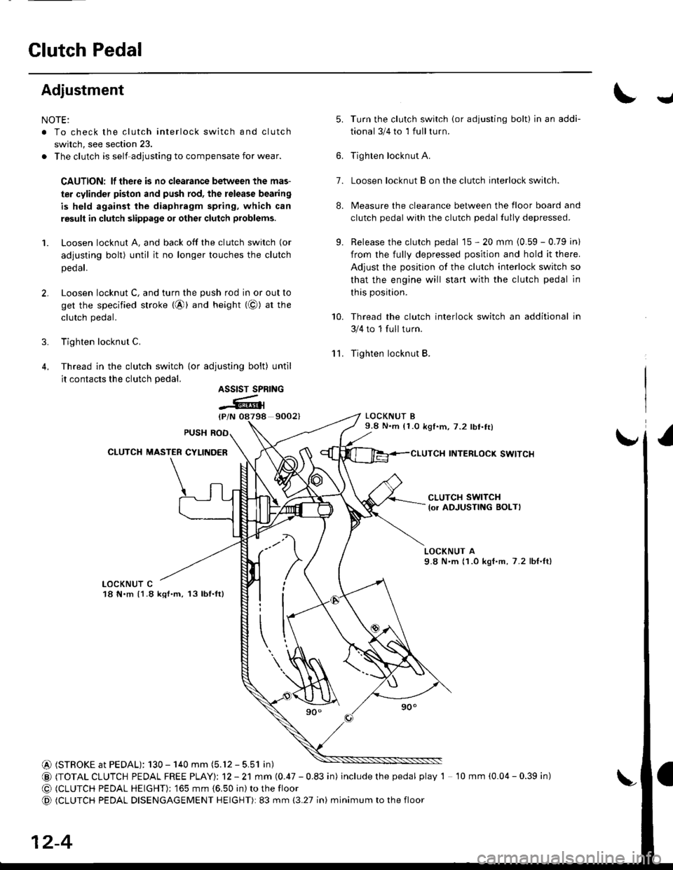
Glutch Pedal
Adjustment
NOTE:
. To check the clutch interlock switch and clutch
switch, see section 23.
. The clutch is self-adjusting to compensate for wear.
CAUTION: lf there is no clearance between the mas-
ter cylinder pislon and push rod, the release bearing
is held against the diaphragm spring, which can
result in clutch slippage 01 other clutch problems.
1. Loosen locknut A, and back off the clutch switch (or
adjusting bolt) until it no longer touches the clutch
peoar.
2. Loosen locknut C, and turn the push rod in or out to
get the specified stroke {@} and height (@) at tne
clutch pedal.
3. Tighten locknut C.
4. Thread in the clutch switch {or adiusting bolt) until
it contacts the clutch pedal.
9002)
Turn the clutch switch (or adjusting bolt) in an addi-
tional 3/4 to 1 full turn.
Tighten locknut A.
Loosen locknut B on the clutch interlock switch.
Measure the clearance between the floor board and
clutch pedal with the clutch pedal fully depressed.
Release the clutch pedal 15 - 20 mm {0.59 - 0.79 in)
from the fully depressed position and hold it there.
Adjust the position of the clutch interlock switch so
that the engine will start with the clutch pedal in
this position.
Thread the clutch interlock switch an additional in
3/4 to 1 full turn.
Tighten locknut B.
LOCKNUT B9.8 N.m (1.0 k91.m,7.2 lbt.tt)
INTERLOCK SWITCI{
J
'lL
5.
7.
8.
9.
10.
ASSIST SPRING
-Atl
CLUTCH SWITCH
lo. ADJUSTING BOLTI
LOCKNUT A9.8 N'm (1.0 kgI.m, 7.2 lbf,ft)
LOCKNUT C18 N.m {1.8 kql.m, 13lbf.ft}
@ (STROKE at PEDAL): 130 - 140 mm (5.12 - 5.51 in)
@ (TOTAL CLUTCH PEDAL FREE PTAYI: 12 - 21 mm (0.47 - 0.83 in) includethepedal play 1 10 mm (0.04 - 0.39 in)
@ (CLUTCH PEDAL HEIGHT): '�]65 mm {6.50 in) to the floor
@ (CLUTCH PEDAL DISENGAGEMENT HEIGHT): 83 mm (3.27 in) minimum to the floor
12-4
Page 583 of 2189
MaintenanceBack-up Light Switch
Transmission Oil
NOTE: Check the transmission oil with the engine OFF
and the vehicle on level ground.
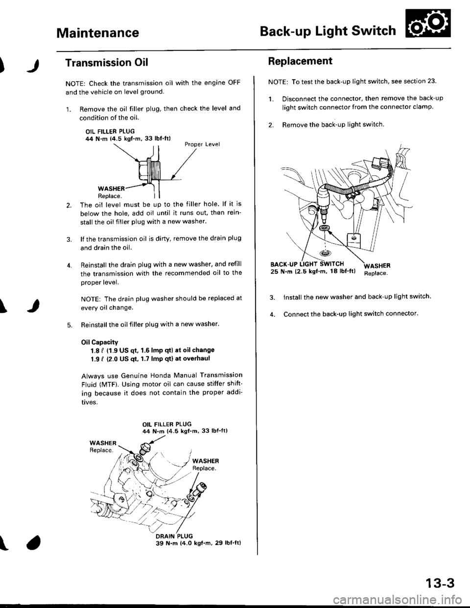
1. Remove the oil filler plug, then check the level and
condition of the oil.
OIL FILLER PLUG/14 N.m (4.5 kgl.m,33 lbl.ft)Proper Level
4.
WASHERReplace.
The oil level must be up to the filler hole. lf it is
below the hole, add oil until it runs out. then rein-
stall the oil filler plug with a new washer.
lf the transmission oil is dirty, remove the drain plug
and drain the oil.
Reinstall the drain plug with a new washer, and refill
the transmission with the recommended oil to the
proper lever.
NOTE: The drain plug washer should be replaced at
every oil change.
Reinstall the oil filler plug with a new washer.
OilCapacity
1.8 f (1.9 US qt. 1.6 lmp qtl at oil change
1.9 { (2.0 US $, 1.7 lmp qt) at overhaul
Always use Genuine Honda Manual Transmission
Fluid {MTF). Using motor oil can cause stiffer shift-
ing because it does not contain the proper addi-
t|ves.
\
\
Replacement
NOTE: To test the back-up light switch, see section 23
1. Disconnect the connector, then remove the back-up
light swirch connector from the connector clamp.
2. Remove the back-up light switch.
25 N.m (2.5 kgf'm, 18lbf'ltl
Install the new washer and back-up light switch
Connect the back-up light switch connector.
ASHER
13-3