2000 HONDA CIVIC Section 23
[x] Cancel search: Section 23Page 443 of 2189

PGM-FI System
l-Fos3sl
tFos36l
tF1361 l
Fr362-1
tF13sil
Crankshaft Position/Top Dead Center/Cylinder Position (CKP/TDC/CYPI Sensor
f99 - 00 Models except D16Y5 engine with M/T)
The scan tool indicates Diagnostic Trouble Code (DTC) P0335: A malfunction in the Crankshaft Position (CKP)
sensor circuit.
The scan tool indicates Diagnostic Trouble Code (DTC) P0336: A range/performance problem in the Crankshaft
Position (CKP) sensor circuit.
The scan tool indicates Diagnostic Trouble Code (DTC) P1361: Intermittent interruption in the Top Dead Center
{TDC) sensor circuit.
The scan tool indicates Diagnostic Trouble Code {DTC) P1362: No signal in the Top Dead Center (TDC) sensor
circuit.
The scan tool indicates Diagnostic Trouble Code (DTC) P1381: Intermittent interruption in the Cylinder Position(CYP) sensor circuit.
lTiaSt The scan tool indicates Diagnostic Trouble Code (DTC) P1382; No signal in the Cylinder Position (CYP) sensor: circuil.
DoscriDtion
The CKP Sensor determines timing for fuel injection and ignition of each cylinder and also detects engine speed. The TDC
Sensor determines ignition timing at start-up (cranking) and when crank angle is abnormal. The CYP Sensor detects the
position of No. 1 cylinder for sequential fuel injection to each cylinder. The CKP/TDC/CYP Sensor is built into the distribu-
tor.
NOTE; lf DTC P1359 is stored at the same time as DTC P0335, P0336, P1361. P1362, P1381 and/or P1382, troubleshoot DTC
P1359 first, then recheck for those DTCS. D16Y5 engino:
SENSORROTOR
TDGSENSORCKPSENSOBTDCSENSOBCKPSENSOBCYPs€NsonBOTORROTORBOTONROTOR ROTOR
D16Y7, D16Y8 ongine:
(To page 11-175)
1-174
- The MIL has been reportod on.- DTC P0335, P0336. P1361,P1362, P1381 rnd/or P1382.restored.
Problem verific{tion:1. Do the ECM/PCM Reset Proce-dure.2. Start the engine.
Intormittcnt failure, systom b OKat thb time. Check to. poor con-nections or loose wires at C120(dktributorl and ECM/PCM.
ls DTC P0335, P0336, P1361, P1362,P1381 and/or Pl382 indicated?
Check tor an open in the CKP/TDC/CYP 3enior:1. Turn the ignition switch OFF.2. Disconnect the distributor 10Pconnector,3. Measure resistance betweenthe terminals of the indicatedsensor (*see table).
Replrce the distributor ignitionhou3ing (!ee section 231.ls there 350 700 0?
SENSORDTCSENSORTEBMINAIECM/PCMTERI\,4INAICOLOR
CKPP0335
P0336
2c88LU
6c9
TDCP1361
P1362
3c20GRN
7c21BED
CYPP1381
P1342
c29YEL
Ic30BLK
Page 445 of 2189
PGM-FI System
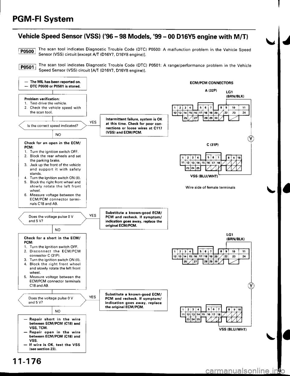
Vehicle Speed Sensor (VSSI ('96 - 98 Models,'99 - 00 D16Y5 engine with M/Tl
@The scan tool indicates Diagnostic Trouble Code (DTC) P0500: A malfunction problem in the Vehicle SpeedSensor (VSS) circuit Iexcept A!/T (D16Y7, D16Y8 engine)1.
The scan tool indicates Diagnostic Trouble Code (DTC) P0501: A range/performance problem in the VehicleSpeed Sensor (VSS) circuit [A,rT {D16Y7, D16Y8 engine)].
ECM/PCM CONNECTORS
A {32P} LG.t
VSS IBLU/WHT}
Wire side ot temale terminals
LGI(BRN/8LK}
The MIL has been reDorted on.DTC P0500 or P0501 is stored.
Problem verification:1- Test drive the vehicle.2. Check the vehicle speed withthe scan tool.
Intermittent tailure, system is OKat this time. Check tor Door con-nections or loose wires at C117{VSSland ECM/PCM.
ls the correct speed indicated?
Check for an open in the ECM/PCM:1. Turn the ignition switch OFF.2. Elock the rear wheels and setthe parking brake.3. Jack up the front of the vehicleand support it with safetystands.4. Turn the ignition switch ON (ll).
5. Block the right tront wheel andslowly rotate the left front
6, Measure voltage between theECM/PCM connector termi-nals C18 and A9.
Subslitute a known-good ECM/PCM and recheck. lf symptom/indic.tion goes away, replace theorisinal ECM/PCM.
Does the voltage pulse 0 Vand 5 V?
Check tor a short in ihe ECM/PCM:1. Turn the ignition switch OFF.2. Disco n n ect the ECM/PCMconnector C (31P).
3. Turn the ignition switch ON {ll).4. Block the right front wheeland slowly rotate the left front
5. Measure voltage between theECM/PCM connector terminalsC18 and A9.
Substitute a known-good ECM/PCM and recheck. lI symptom/indication goes away. replacethe original ECM/PCM.
Does the voltage pulse 0 Vand s V?
- Repair short in the wirebetwGen ECM/PCM {C18} endvss, TcM.- Repair open in the wirebetween ECM/PCM {Cl8} andvss.- lf wire is OK, test the VSSlsee section 23).
{BRN/BLK}
239l0lt
121611t8t9202321
2A2930
c {31P}
I38191o
tl12ialr5i6l10./
I2356a9l011
12l3l5t61tl8t920222a
27202930
12910
t2l13l.l7I l,/ 1,/231r.lslt., ),rlL
VSS {BLU/WHT}
11-176
Page 460 of 2189
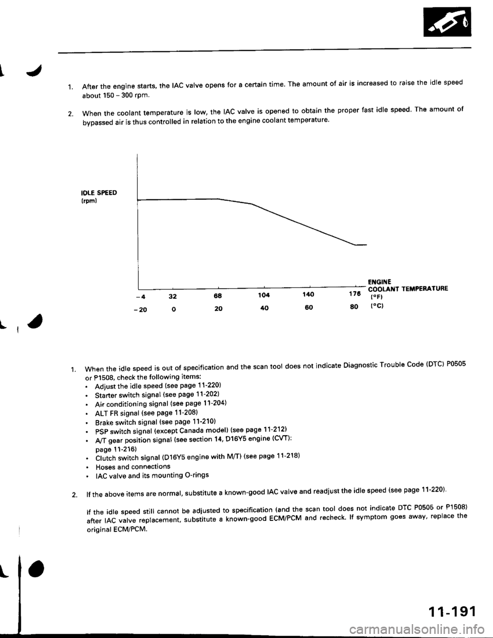
1.After the engine starts, the lAc valve opens for a certain time. The amount of air is increased to raise the idle speed
about 150 - 300 rpm.
When the coolant temperature is tow, the IAC valve is opened to obtain the proper fast idle speed. The amount of
bypassed air is thus controlled in relation to the engine coolant temperature'
IOLE SPEED
lrpml
176
80
ENGI ECOOLANI TEMPERATURE
t" Fl
toc)
ll
't.Whentheid|espeedisoutofspeciiicationandthescantoo|doesnotindicateDiagnosticTroub|ecode(DTc)P0505
or P1508. check the following items:
. Adiust the idle speed {see page 11-220}
. Starter switch signal (see page 11-202)
. Air conditioning signal (see page l1-204)
. ALT FR signal (see Page 11-2081
' Brake switch signal (see page 11-210)
. PSP switch signal (excapt Canada model) (see page 11-212)
. A,/T gear position signal {see section 14, Dl6Y5 engine (CVT):
page 11-216). Clutch switch signal (D16Y5 engine with M/T) (see page 11-218)
. Hoses and connections
' IAC valve and its mounting O-rings
lf the above items are normal, substitute a known-good IAC valve and readjust the idle speed (see page 11-220)
|ftheid|espeedsti||cannotbeadjustedtospecification(andthescantoo|doesnotindicateDTcP0505orP]50S)
after IAC valve replacement. substitute a known-good ECM/PCM and recheck. lf symptom goes away, replace the
original ECM/PCM.
Page 473 of 2189
ldle Gontrol System
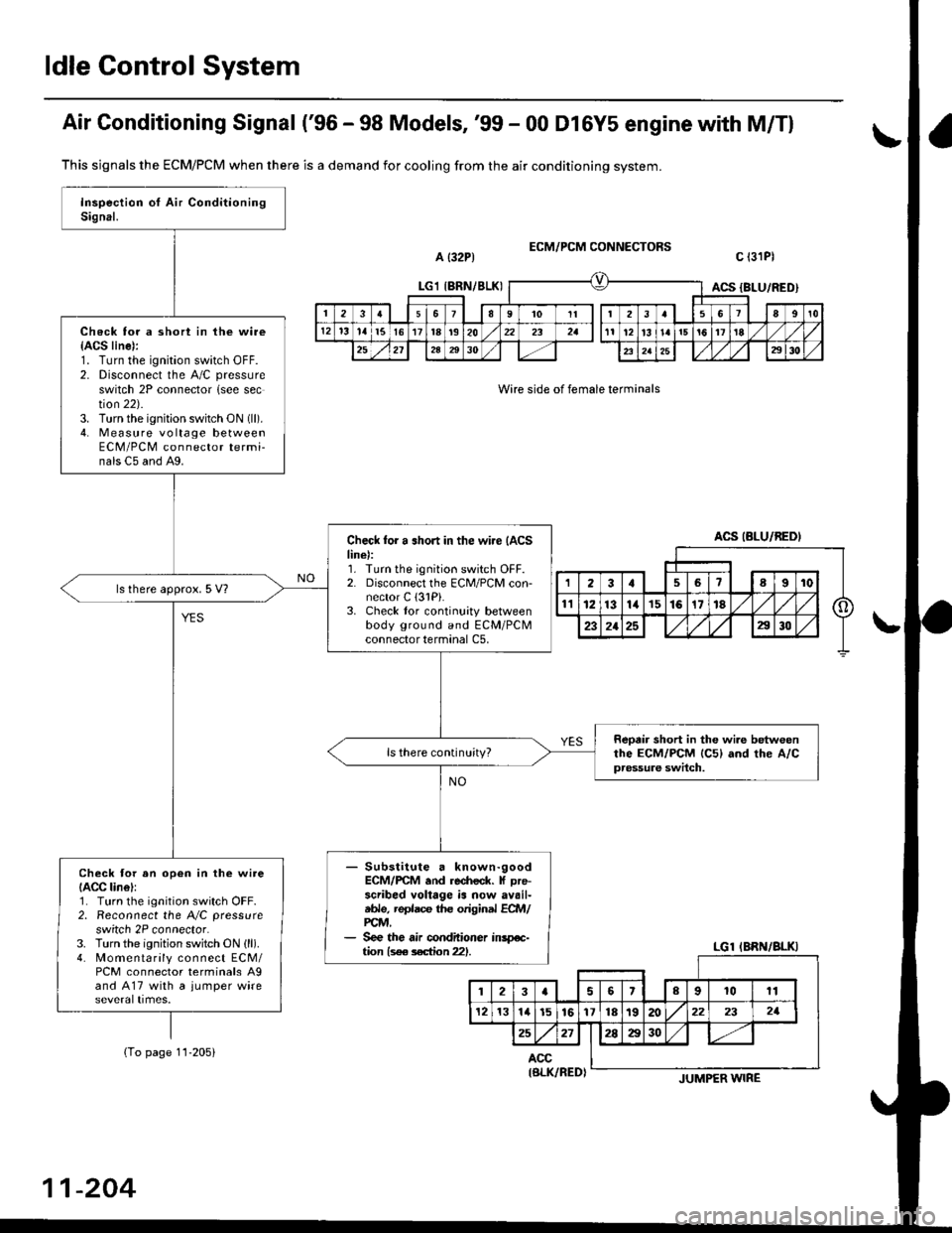
Air Gonditioning Signal ('96 - 98 Models, '99 - 00 Dl6Y5 engine with M/Tl
a {32P1ECM/PCM CONNECTORS
Wire side of female terminals
c l3lPl
This sjgnals the ECM/PCM when there is a demand for cooling from the air conditioning system.
(To page 11-205)
Check for a short in the wire{ACS line):1. Turn the ignition switch OFF.2. Disconnect the A/C pressure
switch 2P connector {see section 22).3. Turn the ignition switch ON (ll).
4. Measure vo lta ge betweenECM/PCM connector termi-nals C5 and A9.
Check for a .hort in the wi.e {ACSline):1. Turn the ignition switch OFF.2. Disconnect the ECM/PCM con-nector C (3lPi.
3. Check tor continuity betweenbody ground and ECM/PCMconnector terminal C5,
ls there approx. 5 V?
Reotir short in the wi.e betweenthe ECM/PCM lc5l and rhe A/Cpressure switch.
ls there continuity?
- Substitute a known-goodECM/rcM .nd re.fieck. f Dre-scribed voltage is now availtble, replace the original ECft4/PCM,- See the air conditioner inspe-tion ls€e s€ction 221.
Check tor an op€n in the wireIACC lin6l:1. Turn the ignition switch OFF.2. Reconnect the A/C pressure
switch 2P connector.3. Turn the ignition switch ON (ll).
4. Momentarily connect ECM/PCM connector terminals A9and A17 with a jumper wire
LGl IBRN/8LKIACS {BLU/RED)
2361I9't0Itt3a89t0
12't31al5l617t8t920232all12l3l!ai5!617'tE
252l2A2930232a252930
ACS (BLU/BEDI
LGl IBRN/BLKI
123aslslrl lolgl ro lrr I
121314l516y)nltslnl/@) zr I zr I
25271!M1 1-/r
ACC
11-204
IBLK/RED)JUMPER WIRE
Page 476 of 2189

I
JUMP€RWIRE
UNDER-HOOO FUSE/RELAYsox 9P coNNEcroR lca52l
123a
5689
ACC (8LK/REDI
Wire side ofterminals
ECM/PCM CONNECTORS
A (32P1
female
Wire side of {emale terminals
(From page 11-206)
Check for an open in the wite
IACC lino):Momentarily connect under_hood
luse/relay box 9P connector teF
minal No. 5 to body ground with
a jumper wire several times.
ls there a clicking noise from
the Iy'C compressor clutch?
S6e air conditioner insPoction
l3oa section 221ls there a clicking noise lrom
the ly'C compressor clutch?
Ropair open in tho wilo betwg€n
the ECM/PCM lA17) and the A/C
clutch rolay.
Chock for the oporation of lho
AIC:1, Start the engine.
2. Turn the blower switch ON
3. Turn the ray'C switch ON.
Check lor an open in the wiro(ACS lino):Measure voltage between ECM/
PCM connector terminals A27
and 820.
Does the Iy'C operate?
Air conditioning signal is OK.Repair op6n in the wiro bctwoon
lhe ECM/PCM lA27l and tho A/C
3witch.ls voltage lessthan 1.0 V?
- Sub6iitut€ r known€ood ECtt /PCM and rccheck. ll sYmP-
tom/indication 9oe3.waY,replaca the original ECM/PCM- See the ai. condhionGr in3p€c-tion lsee soc{ion 221.
11-207
Page 479 of 2189
ldle Control System
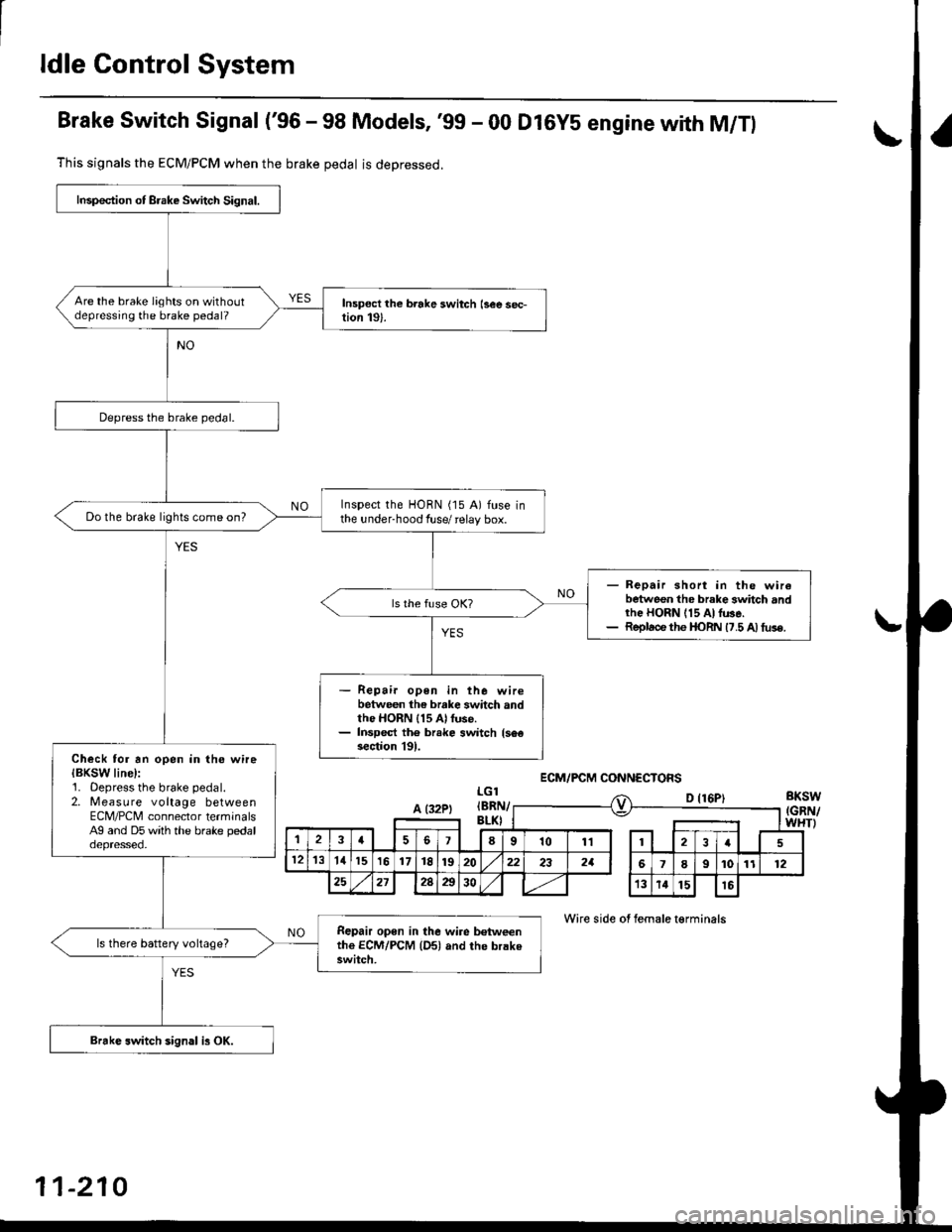
Brake Switch Signal ('96 - 98 Models, '99 - 00 Dl6YS engine with M/Tl
This signals the ECM/PCM when the brake pedal is deoressed.
LGlBKSW(GRN/WHTI
D {16P)
Wire side of female t€rminals
Inspection of Brake Switch Signal.
Are the brake lights on withoutdepressing the brake pedal?
Depress the brake pedal.
Inspect the HORN (15 A) fuse inthe under-hood fuse/ relay box.Do the brake lights come on?
- Repair short in the wirebetween the brake 3whch andrhe HORN 115 At lu3e.- Replace the I|oRN 17.5 A) tus€.
Repair open in the wirebetween the brake switch andthe HORN 115 Al fuse.Inspect th6 br.ke switch {s6€section l9l.Check tor an open in the wireIBKSW line):1. Oepress the brake pedal.2. Measure voltage betweenECM/PCNI connector terminalsAg and D5 with the brake pedaloepresseo.
Repair open in the wire b€tweenthe ECM/PCM {Dsl and the brakeswitch.
ls there battery voltage?
Brakc switch sign.l is OK.
ECM/PCM CONNECTOFS
A (32PtIBRI\v
,la678101112I
121311151617t8192022232aI9101112
25212Aa3013141516
11-210
Page 480 of 2189
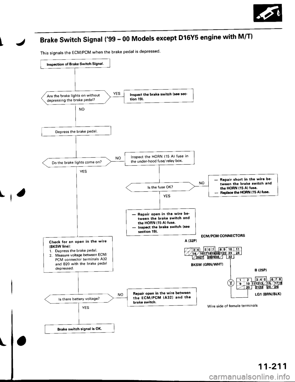
IJBrake Switch Signal ('99 - 00 Models except Dl6Y5 engine with M/Tl
This signals the ECM/PCM when the brake pedal is depressed
I
lnsoection ot Brake Switch signal.
Are the brake lights on without
depressing the brake Pedal?
Depress the brake Pedal
Inspect the HoRN {15 A} fuse in
the underhood fuse/ relay box'Do the brake lights come on?
- R.pair short in the wiro be'
tween the brake switch and
the HORN (15 Alfuse.- Replac€ the HORN (15 A) tuse.
- Repair open in the wite be'
tween the brako switch and
the HORN (15 Alfuse.- lnsoect the brake switch (3ec
section tgl.
Check fot an oPen in the wire
{BKsw linel:
1. Depress the brake Pedal.2. Measure vohage beween ECM/
PCM connector terminals A32
and 820 with the brake Pedaldepressed.
Bepair open in the wire between
the ECM/PCM (A32) and the
brake switch.
Brake switch signal i5 OK
ECM/PCM CONNECTORS
BKSW (GRN/WHTI
LG1 {BRN/BLK)
Wire side o{ female terminals
Page 489 of 2189

ldle Control System
ldle Speed Setting
Inspection/Adiustmenl
'96, '97 Dl6Y5. '96 - 00 Dl5Y8 sngine with M/T
NOTE:
. Before setting the idle speed, check the following
items:- The MIL has not been reported on.- lgnition timing- Spark plugs- Air cleaner- PCV system
o (Canada) Pull the parking brake lever up. Start the
engine, then check that the headlights are off.
1. Start the engine. Hold the engine at 3.000 rpm withno load (taansmission in neutral) until the radiatorfan comes on, then let it idle.
2. Connect a tachometer.
3. Disconnect the IAC valve connector.
4.lf the engine stalls, restart the engine with the accel-
erator pedal slightly depressed. Stabilize the rpm at1,000, then slowly release the pedal until the engineidles.
Check idling in no-load conditionsr headlights. blowerfan. rear defogger, radiator fan, and air conditioner
are not operating.
ldle spsed should be:
450 1 50 rpm
11-220
Adjust the idle speed, if necessary, by removing thecap and turning the idle adjusting screw.
NOTE; After adjusting the idle speed in this step,recheck the ignition timing (see section 23).
lf it is out of spec, go back to step 4.
IDLE
6. Turn the ignition switch OFF.
7. Reconnect the 2P connector on the IAC valve, then
do the ECM reset procedure.
8. Restart and idle the engine with no-load conditionsfor one minute, then check the idle speed.
NOTE: (Canada) Pull the parking brake lever up.Start the engine, then check that the headlights areoff.
ldle sp€sd should b€:
670 i 50 rpm IUSA)750 t 50 rpm {Canada}
9. ldle the engine tor one minute with headlights {Low)ON. and check the idle speed.
ldle speed should be:
750 :r 50 rpm
10. Turn the headlights off. ldle the engine for oneminute with heater fan switch at Hl and air conditioneron, then check the idle speed.
ldle speed should be:
810150 rpm
NOTE: lf the idle speed is not within specification,see Symptom Chan on page 11-84.