Page 1000 of 2189
4. Compress the return sprlng.
Remove the snap ring. Then remove the special tools,
spring retainer, and return spring.
SPBING RETAIT{€R
6. Wrap a shop rag around the clutch drum, and apply
air pressure to the fluid passage to remove the piston.
Place a finger tip on the other end while applying air
pressure.
OSHA-APPROVED30 psi NOzzLE
14-323
Page 1001 of 2189
Forward Glutch
Reassembly
NOTE:
. Clean all parts thoroughly in solvent or carburetor
cleaner, and dry them with compressed air.
. Blow out all passages.
. Lubricate all parts with CW Fluid before reassembly.
1. Inspect the check valve; if it's loose, replace the pis-
ton.
CHECK VALVE
Install new O-rings on the clutch pision.
PISTON
14-324
3. Install the piston in the clutch drum. Apply pressure
and rotate to ensure proper seatang,
NOTE: Lubricate the piston O-ring with CVT Fluid
before installing.
CAUTION: Do not pinch thc O-ring by installing the
pistoo with too much torqo.
CLUTCH DRUM
Install the return spring and spring retainer, and
position the snap ring on the retainer.
CLUTCH DRUM
Page 1014 of 2189
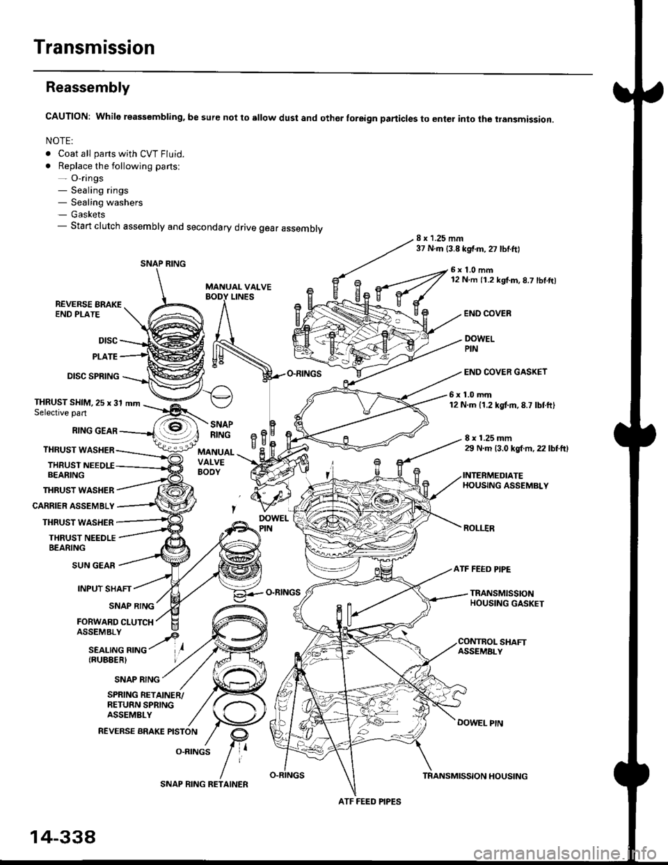
Transmission
Reassembly
CAUTION: While reassembling. be sure not to sllow dust and othor foreign particles to enter into the transmission.
NOTE:
. Coat all parts with CVT Fluid.
. Replace the following parts:- O-rings- Sealing rings- Sealing washers- Gaskets- Start clutch assembly and secondary drive gear assembly8 x 1.25 mm37 N.m {3.8 kgf.m,27 lbtftl
MANUAL VALVE
6x1.0mm12 N m 11.2 kgf.m,8.7 lbl.ft)
LINESREVERSE BRAKEEND PLATE
Dtsc
PLATE
DISC SPRING
THRUST WASHER
CARRIER ASSEMBLY
THRUST WASHER
THRUST NEEDLEBEARING
END COVEB
DOWELPIN
END COVER GASKET
6x1.0mm12 N.m 11.2 kgtm,8.7 lbtft)THRUST SHIM,25 x 31 mmSelective part
RING GEAR
THRUST WASHER
THRUSTBEARING
8 x 1.25 mm29 N.m 13.0 kgl m, 22 lbtftl
INTERMEDIATEHOUSING ASSEMBLY
ROLI.IR
SNAPRINGeBH^cMANUALVALVEBOOY
SUN GEAR
INPUT SHAFT
(RUBEERI
ATF FEED PIPE
O-RINGSTRANSMISSIONHOUSING GASKETSNAP RING
FORWARD CLUTCH
SNAP RING
SHAFTASSEMALY
DOWEL PtN
SPRING RETAINER/RETURN SPRINGASSEMBLY
REVERSE BRAKE PISTON
O.RINGS
SNAP RING
ATF FEED PIPES
14-338
SNAP RING RETAINERTRANSMISSION HOUSING
Page 1015 of 2189
1.
7.
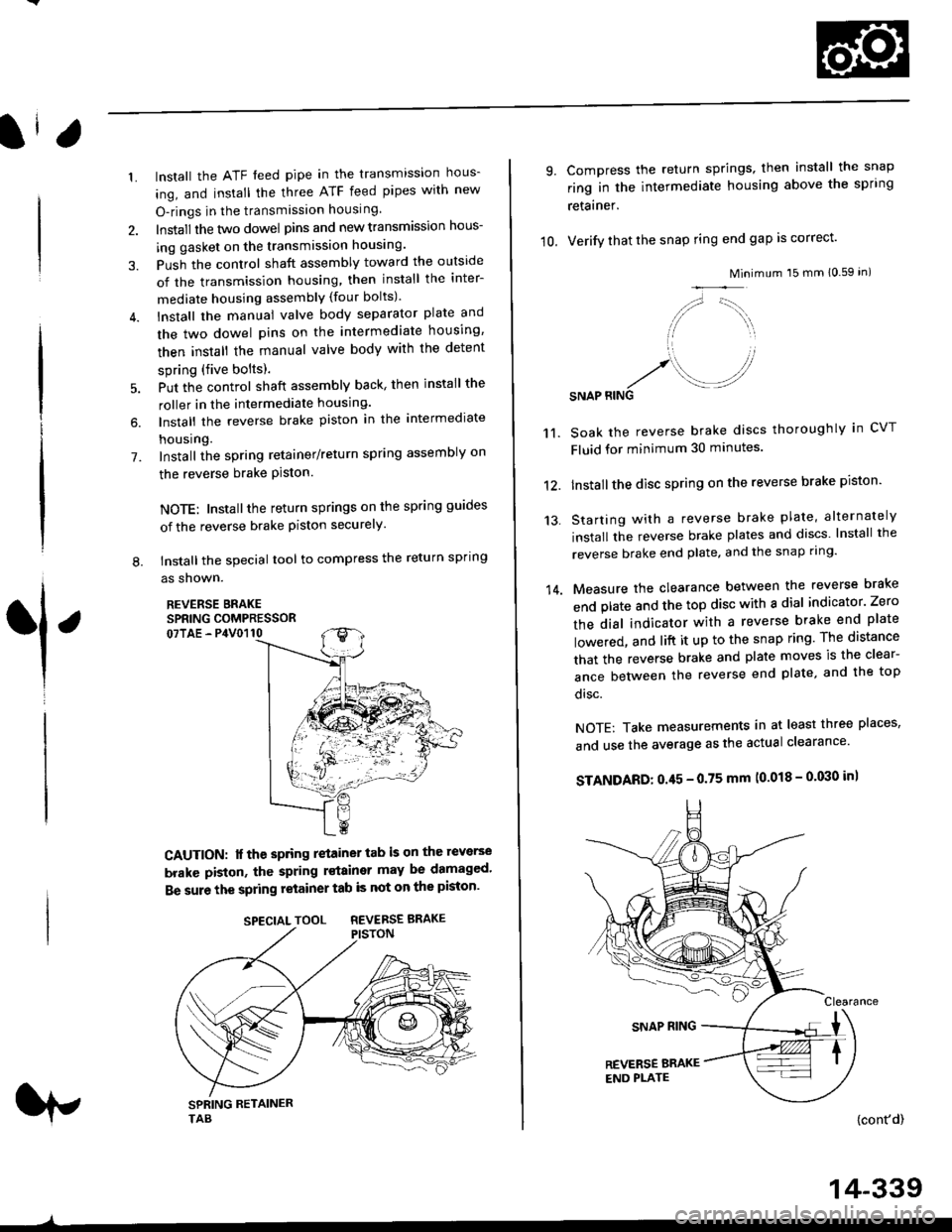
lnstall the ATF feed pipe in the transmission hous-
ing, and install the three ATF feed pipes with new
O-rings in the transmission housing,
Install the two dowel pins and new transmission hous-
ing gasket on the transmission housing.
Push the control shaft assembly toward the outside
of the transmission housing, then install the inter-
mediate housing assembly (four bolts).
lnstall the manual valve body separator plate and
the two dowel pins on the intermediate housing,
then install the rnanual valve body with the detent
spring (five bolts).
Put the control shaft assembly back, then install the
roller in the intermediate housing.
lnstall the reverse brake piston in the intermediate
housing.
Install the spring retainer/return spring assembly on
the reverse brake Piston.
NOTE: Installthe return springs on the spring guides
of the reverse brake piston securely
tnstall the special tool to compress the return spring
as shown.
REVERSE BRAKESPRING COMPRESSOR07TAE - P4V0110
6.
L
1
CAUTION: lf the spring retainer tab is on the reverse
brakc piston, the spring rstainer may be damaged'
Be sure the spring retainer tab is not on the piston'
rp
SPECIALTOOL REVERSEBRAKE
-^
14-339
10.
9.
14.
Compress the return springs, then install the snap
ring in the intermediate housing above the spring
retainer.
Verify that the snap ring end gap is correct'
Mini
/,,- '-t,,,,.
// \i/ ',r
'1 ,
.r' //'/. .-J?RINGSNAP
mum 15 mm 10.59 in)
Soak the reverse brake discs thoroughly in CVT
Fluid for minimum 30 minutes.
Installthe disc spring on the reverse brake piston'
Starting with a reverse brake plate, alternately
install the reverse brake plates and discs lnstall the
reverse brake end plate, and the snap ring'
Measure the clearance between the reverse brake
end plate and the top disc with a dial indicator' Zero
the dial indicator with a reverse brake end plate
lowered, and lift it up to the snap ring The distance
that the reverse brake and plate moves is the clear-
ance between the reverse end plate, and the top
disc.
NOTE: Take measurements in at least three places'
and use the average as the actual clearance'
STANDARD: 0.45 - 0.75 mm (0.018 - 0'030 in)
{cont'd)
11.
12.
13.
Page 1058 of 2189
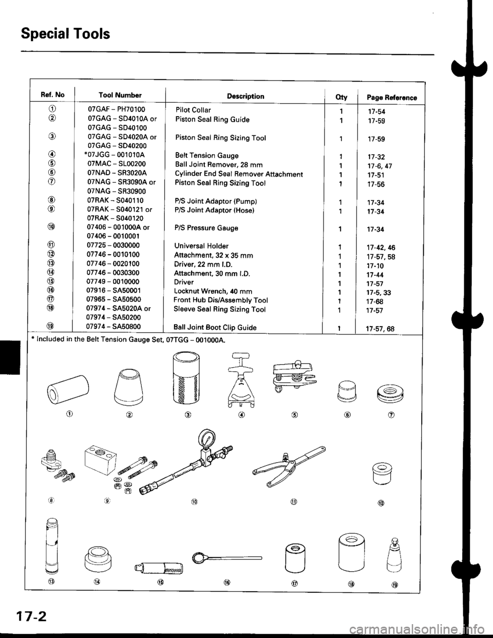
Ref. No I Tool NumberDescriptionOty I Pag€ Reterence
o
@
@
@
@
fof
@
@
@
@
@
@
@
@
@
@
@
@
@
07GAF - PH70100
07GAG - SD4010A or
07GAG - SD40100
07GAG - SD4020A or
07GAG - S040200*07JGG - 00r 010A
07MAC - 5100200
OTNAD - SR3O2OA
07NAG - SR3090A or
07NAG - SR30900
07RAK - 5040110
07RAK - 5040121 or
07RAK - 5040t20
07406 - 0010004 or
07406 - 001000r
07725 - 0030000
07746 - 0010100
07746 - 0020100
07746 - 0030300
07749 - 0010000
07916 - SA50001
07965 - SA50500
07974 - SA5020A or
07974 - SA50200
07974 - SA50800
Pilot Collar
Piston Seal Ring Guide
Piston Seal Ring Sizing Tool
Belt Tension Gauge
Ball Joint Remover, 28 mm
Cylinder End Seal Bemover Attachment
Piston Seal Ring Sizing Tool
P/S Joint Adaptor (Pump)
P/S Joint Adaptor (Hose)
P/S Pressure Gauge
Universal Holder
Attachment,32 x 35 mm
Driver, 22 mm l.D.
Attachment, 30 mm l.D.
Driver
Locknut Wrench, 40 mm
Front Hub DiVAssembly Tool
Sleeve Seal Ring Sizing Tool
Bsll Joint Boot Clip Guide
1
1
'I
1'I
1
I
1
1
I
1
1
I
1
1
I
1
I
11-54
17-59
'17-59
17 -32
17 -6, 47
17-51
| /-ao
17 -34
17 -31
't7 -34
't7-42, 16
17-57,58
17-10
17-44't7 -57
17-5,33
17-68
17 -57
17-57, 6A* lncluded in the Belt Tension cauge Set, 07TGG - OO10OOA.
o
p
v
@o
€_
ts7-dysB
aal
@@
(o)
F=1
@@@
@@@
17-2
Page 1077 of 2189
Pressure Control
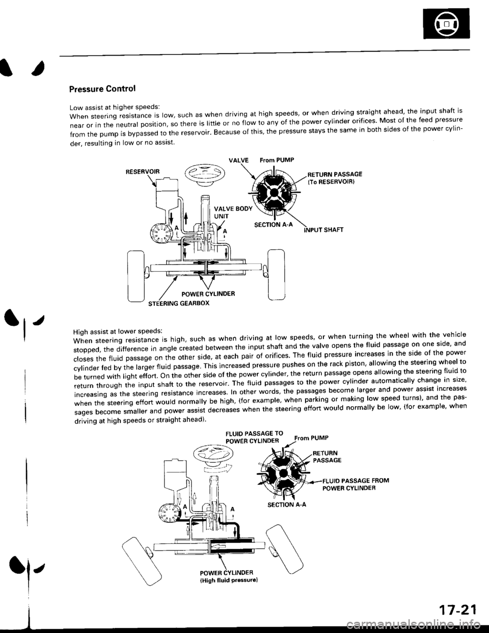
Low assist at higher speeds:
WhensteeringresistanceIsIow,suchaswhendrivingathighspeeds,orwhendrivingstraightahead,theinputshaftis
near or in the neutral position, so there is little or no fiow ro any of the power cylinder orifices. Most oI the feed pressure
fromthepumpisbypassedtothereservoir.Becauseofthis,thepressurestaysthesameinbothsidesofthepowercy||n-
der, resulting in low or no asslst
VALVE From PUMP
SECTION A-A
RETURN PASSAGElTo RESERVOIRI
POWER CYLINDER
STEERING GEARBOX
High assist at lower speeds:
When steering resistance is high. such as when driving at low speeds' or when turning the wheel wirh the vehicle
stopped,thedifference|nang|ecreatedbetweentheinputshaftandtheVa|veopensthef|uidpassageononeside,and
c|osesthefluidpassageontheotherside,ateachpairoforifices'Thef|uidpressureincreasesinthesideo|thepower
cy|inder|edbythe|argerf|uidpassage'Thisincreasedpressurepushesontherackpiston,a|lowingthesteeringwhee|to
be turned with light effort. on the other side of the power cylinder, the return passage opens allowing the steering tluid to
returnthroUghtheinputshafttothereservoir'Thef|uidpassagestothepowercy|inderautomatica||ychangeins|ze,
increasing as the steering resrstance increases. In other words, the passages become larger and power assist increases
when the steering effort would normally be high, (for example' when parking or making low speed turns)' and the pas-
sagesbecomesma||erandpowerassistdecreaseswhenthesteeringeffortwou|dnorma||ybe|ow,(forexamp|e,when
driving at high speeds or straight ahead).
FLUIO PASSAGE TO
POWER CYLINDER
/t=\\a!-4,))
=YjJ
RESERVOIR
SECTION A-A
l'
{High fluid Pressure}
Page 1108 of 2189
Steering Gearbox
Disassembly (cont'dl
22. Carelully pry the piston seal ring and O-ring off theprslon rack.
CAUTION| Be caletul not to damage the inside ofseal ring groove and piston edges when removing
the seal rin9,
Replace.
17-52
Valve Body Unii Disassembly
23. Eefore removing the valve housing, apply vinyl tapeto splines of the pinion shaft.
24. Separate the valve housing from the pinion shaft/
valve using a press.
VALVE HOUSING
Vinylt.pe
PINION SHAFT
Check the inner wall of the valve housing where theseal ring slides with your finger. lf there is a step inthe wall, the valve housing is worn. Replace thevalve housing.
NOTE:
There may be the sliding marks from the sealring on the wall of the valve housing. Replace
the valve housing only if the wall is stepped.When the valve housing is replaced, jnstall new
shim(s) on the bearing surface of the housing toadjust the thickness.
Check the inside of valve housingwhether the wall is stepped.
Page 1112 of 2189
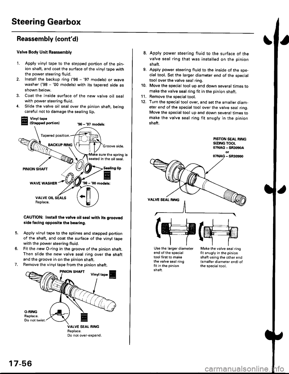
Steering Gearbox
Reassembly (cont'd)
Valve Body Unit Reassembly
1. Apply vinyl tape to the stepped portion of the pin-
ion shaft, and coat the surface of the vinyl taoe with
the power steering fluid.
2. Install the backup ring ('96 -'97 models) or wavewasher ('98 -'00 models) with its tapered side as
shown below.
3. Coat the inside surface of the new valve oil sealwith power steering fluid.
4. Slide the valve oil seal over the pinion shaft, being
careful not to damage the sealing lip.
Vinyl t.po{Stepped ponion}
Tap6red position.
BACKUPGroove side.
sure the spring isseatod in the oil seal.
'98 - '00 mod.b:
CAUTION: InstEll ihe valve oil seal whh its groov.d
3ide tacing opposite tho boaring.
Apply vinyl tape to the splines and stepped portion
of the shaft, and coat the surface of the vinyl tapewith the power steering fluid.
Fit the new O-ring in the groove of the pinion shaft.Then slide the new valve seal ring over the shaft
and the groove in on the pinion shaft.
Remove the vinyl tape from the pinion shaft,
'96 - '97 models:
lip
7.
VALVE SEAL RIiIGReplace.Do not over-expand.
17-56
8. Apply power steering fluid to the surface of the
valve seal ring that was installed on the pinion
shaft.
9. Apply power steering fluid to the inside of the spe-cial tool. Set the larger diameter end of the specialtool over the valve seal ring.
10. Move the special tool up and down several times tomake the valve seal ring fit in the pinion shaft.11, Remove the soecial tool.
12. Turn the special tool over, and set the smaller diam-eter end of the special tool over the valve seal ring.Move the special tool up and down several times tomake the valve seal ring fit snugly in the pinion
shaft.
PISTON SEAL BINGSIZING TOOL07NAG - SR:togoAol07NAG - SR3|X)00
(g(m
Use the larger diameterend of the specialtool first to makethe valve seal ringfit in the pinionshaft.
Make the valve seal ringfit snugly in the pinionshaft using the other end(smaller diameter end) ofthe specialtool.