2000 HONDA CIVIC brake sensor
[x] Cancel search: brake sensorPage 1922 of 2189
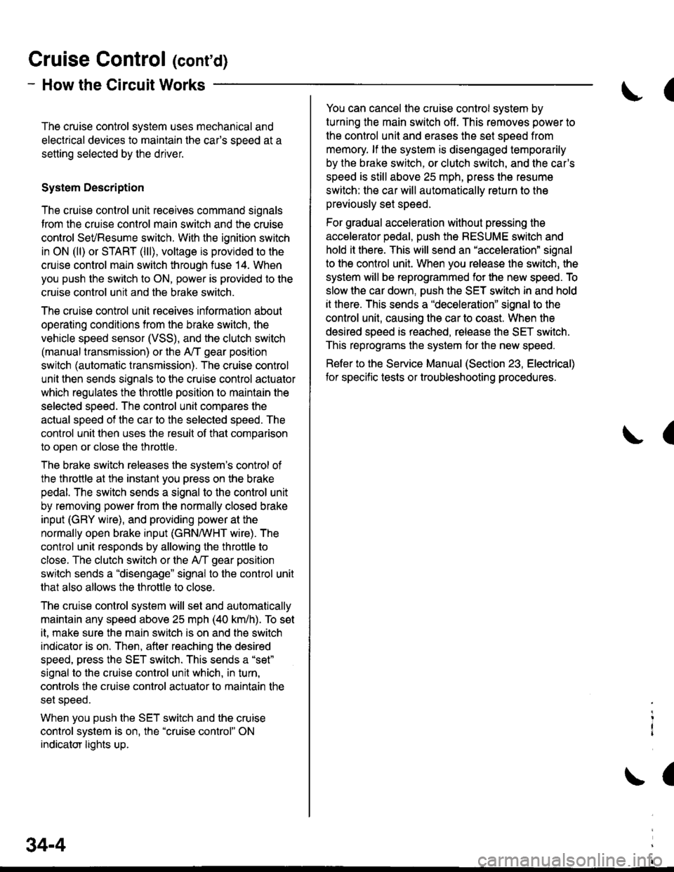
Gruise Control (cont'd)
- How the Circuit Works
The cruise control system uses mechanical and
electrical devices to maintain the car's sDeed at a
setting selected by the driver.
System Description
The cruise control unit receives command signals
from the crurse control main switch and the cruise
control SeVResume switch. With the ignition switch
in ON (ll) or START (lll), voltage is provided to the
cruise control main switch through fuse 14. When
you push the switch to ON, power is provided to the
cruise control unit and the brake switch.
The cruise control unit receives information about
operating conditions from the brake switch, the
vehicle speed sensor (VSS), and the clutch switch
(manual transmission) or the A,/T gear position
switch (automatic transmission). The cruise control
unit then sends signals to the cruise control actuator
which regulates the throttle position to maintain the
selected speed. The conlrol unit compares the
actual speed of the car to the selected speed. The
control unit then uses the result of that comoarison
to open or close the throttle.
The brake switch releases the system's control of
the throttle at the instant you press on the brake
pedal. The switch sends a signal to the control unit
by removing power from the normally closed brake
input (GRY wire), and providing power at the
normally open brake input (GRN/vVHT wire). The
control unit responds by allowing the throttle to
close. The clutch switch or the A,/T gear position
switch sends a "disengage" signal to the control unit
that also allows the throttle to close.
The cruise control system will set and automatically
maintain any speed above 25 mph (40 km/h). To set
it, make sure the main switch is on and the switch
indicator is on. Then, after reaching the desired
speed, press the SET switch. This sends a "set"
signal to the cruise control unit which, in turn,
controls the cruise control actuator to maintain the
set speed.
When you push the SET switch and the cruise
control system is on, the "cruise control" ON
indicator lights up.
34-4
(
You can cancel the cruise control system by
turning the main switch off . This removes power to
the control unit and erases the set speed from
memory. lf the system is disengaged temporarily
by the brake switch, or clutch switch, and the car's
speed is still above 25 mph, press the resume
switch: the car will automatically return to the
previously set speed.
For gradual acceleration without pressing the
accelerator pedal, push the RESUME switch and
hold it there. This will send an "acceleration" signal
to the control unit. When you release the switch, the
system will be reprogrammed for the new speed. To
slow the car down. oush the SET switch in and hold
it there. This sends a "deceleration" signal to the
control unit, causing the car to coast. When the
desired speed is reached, release the SET switch.
This reprograms the system tor the new speed.
Refer to the Service Manual (Section 23, Electrical)
tor specific tests or troubleshooting procedures.
(
a
Page 1923 of 2189
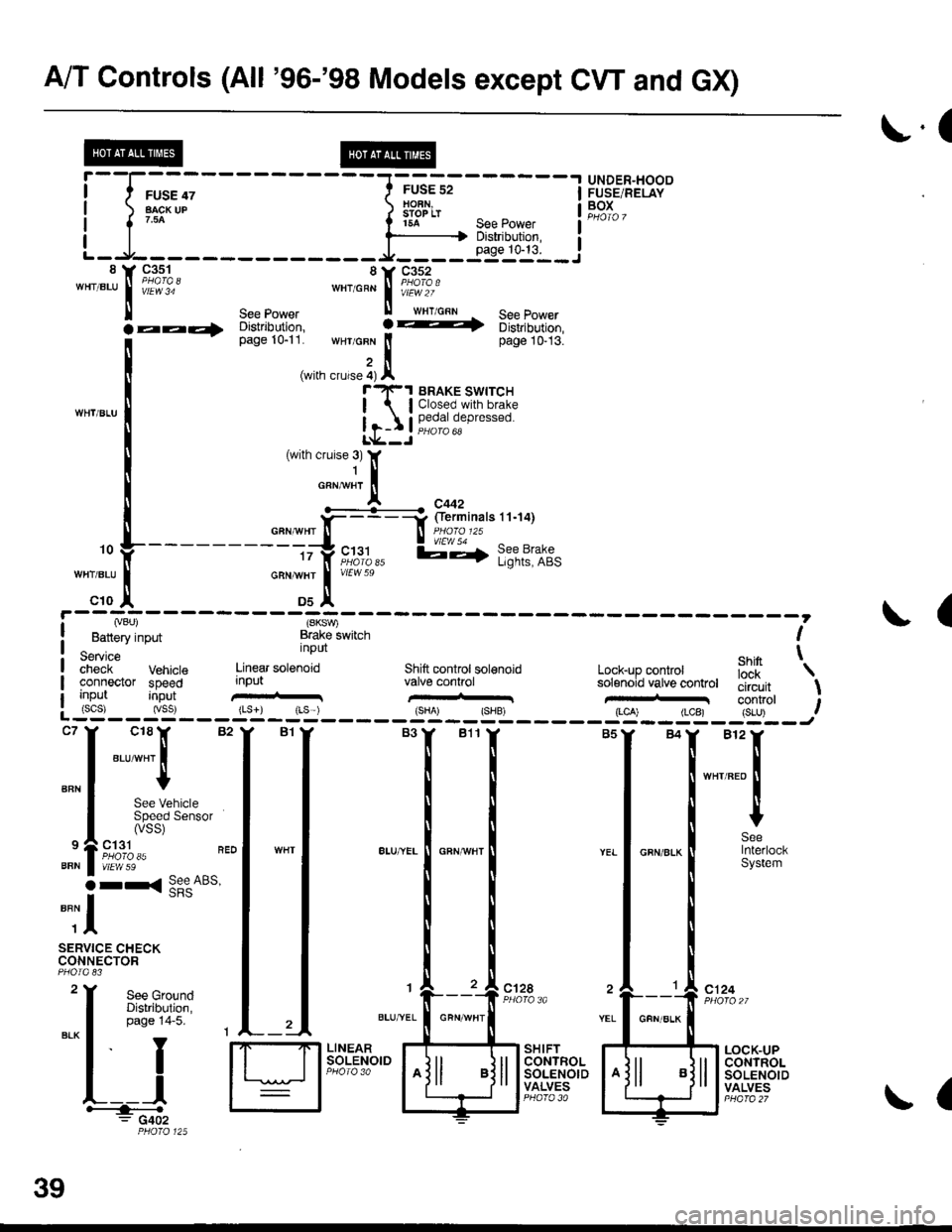
A/T Controls (All '96-'98 Models except CW and GX)
r.(
r5A see power I
--li$"i':,--iL-.At----- __*____..,,53-j"i__8 Y 93^s_1- 8Y C352'"'".u
I iii'i"' ""'o"* | i#?1o.'
ll see power ll wrr cnn See Power
la--- oisirioution, ! -t 6iri,iortion,
[--*
t"*tr*t1,'.':,:;i. wHr GFN lt page 10-13.
,i(with crurse 4) Al"'rl(-1 BRAKE swrrcH
| lClosed.with brake
Ir-I Il,?,|fll,"P'"""oL*--J
c18lr 82
"ar-"t I
I
See VehicleSpeed Sensor(vss)
ct31PHO|O 35vtEw 59
r< See ABs'
UNDER"HOODFUSE/RELAYBOXI
I
I
BFN
9
BFN
o
""il
SERVICE CHECKCONNECTOR
See GroundDistribution,page 14-5.
I
YEL
c124
L__lH:""".: G402
SHIFTCONTROLSOLENOIDVALVES
LOCK-UPCONTROLSOLENOIDVALVES
,. L ---- - - --.#ku" :::::'o f
---------tty"c;11,, l;-,f l;?t?:if,-:;tr *";.!, *"
c10 ,| Ds^'
I Lvou, (SKSV,
! Battery input Brake lwitch I
service nPUt ehin t;;;;i- Vehrcte Linear sotenoid Shift controt sol€noid Lock-up conkol iJ'[
'\
connector speed input valve conhol solenoid vatve controt tliiJ"it \uo trut tconrrol t: (scs) (vss) {Ls}) rLs ) {sHA' {SHB, (LCA) (LCB) {S-U) .--:-'--J
ct28
39
GFN/ALK
(
Page 1927 of 2189

L-L----:-------J----L"egyJ*"" !tr;:tl1tfl i*"?]( 9;%, 8Y ge-q? LJ-------,;li, ! *rr1-....^^ s€s tuwer *"to"n ! if?ror ,r"r,o"n - sse power 14 y g4^1_q --
I
I
o*"clt](/manual-img/13/6068/w960_6068-1926.png)
AIT Controls ('96-'98 CVT)
L-L----:-------J----L"egyJ*"'"' !tr;:tl1tfl' i*"?]( 9;%, 8Y ge-q? LJ-------,;li, ! *rr1-....^^ s€s tuwer *"to"n ! if?'ror' ,r"r,o"n - sse power 14 y g4^1_q --
I
I
o*"'clt. *'"1,!. tad;1di3]
t
-""
I HFr:{tv][[:F I
*l """-tl-.
"*,
*-,-*l
t;
^,.[
"-;;[ 1#E;;;::";mi
.aa4 ;;r;;", : ----+ u,"i.,-uon, i;;;;r.
i {vBt) (sToP sw) (Gl) flc1l
! Battery input Brake switch lgnilion tgniuon| -^-,^^ ' inpui fipr,- i;;i;iSeMce input i;put iiput t
| #;if vehicle Engin€ Drive putley Dnven puttey secondary \-
I cooneaor speed speed speeci sensor speed iens6r gsarshaft'speed t
I
\fa
I input input input input input s€n8or inputI (scsJ {vss} (NE) {ltm) INDN) (vEL)L____-__ -______J".
I
*,ff
I
:l
[
"ili[_==___j
: : : j
I i:isi, fi, &ru"n t$=:{:::==l
[:-,*';|i-.t[d
F'*,Y''"T:."".
H Sig,il H F"ii${* H
$':lry!}Hi"
3lT:T:gl ""lr *=f __-*=!".*,
I ;$f
--l"ur
oFN'BLur !iEi?20
I -rJ-----i.:,-,----=,--^:lrRANsMtsstoN| ;;n's'"
J i$f;:' Si$? $"'":Tiii:e{i.ii'i::^ Is:*",:i !fi8}ltP.n*,;-=:.=-: G402I sround ground grouno I l,llir%lliPHO,O 125 L___-___
39-4
!'cror
Page 1944 of 2189
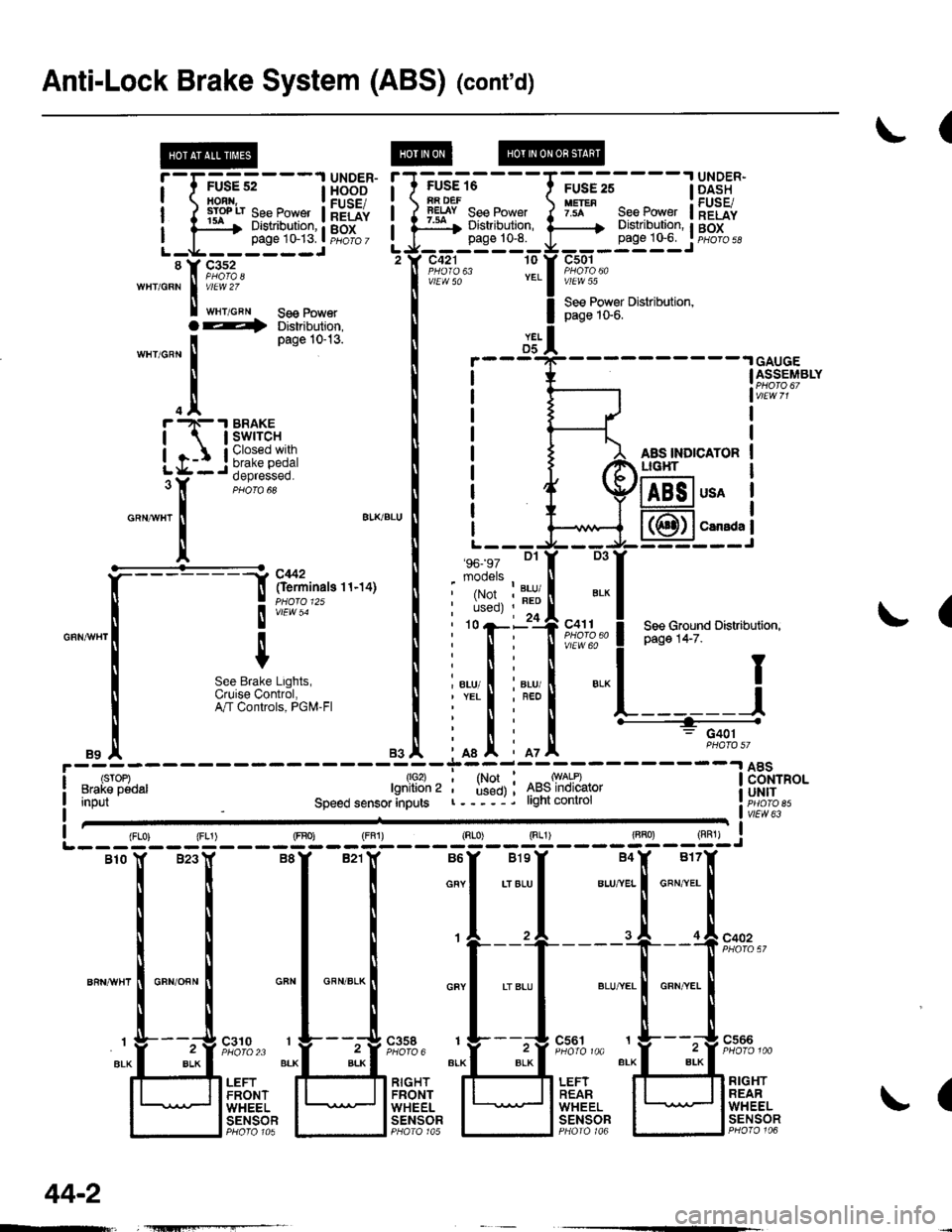
Anti-Lock Brake System (ABS) (cont'd)
(
FUSE 16iA DEFlEtsY See Power:ar Distribution,page 10-8.
c421 10
vlEW 50
'96- 97 Dl
mooels
.I UNDER-
page 1G6. I pHoro 5d
c501
vlEW 55
See Power Distribution,page 1S6.
AAS INDICATORLIG}IT
!'-r;us?;---l H5BE"
ilrryilrfi#ftilHriL-g------JL-g------J'tr F,1%'wHr/GRN I v/El.V 2Z
I t"r,o"" se€ Power
YELD5GAUGEASSEMBLY
usA
CarsdaI
(
D3
', ',i:,tr?""" ! P"g" t+-z".r',
*
! see cround Distributiofl,
".., I i"., I ".-l I;nl
iffit L------J
' n : G401
mI iot
T1*l ^*ry*l:-------l 8Bi"o.' used) ; 4ts5lnolcalor i UH|Tr----j. light conlrol r. iicib ett,"LTfflo",Input
1lo2)lgnition 2
Speed sensor anputsvlEw 63
(
{FLo) {FL1) (FBo) {FF1) (Rr"o) Sg____gT]-__g,l-j
Blo lf B23Y B8Y B21lf B6Y BlsY B4X B17f
i i I i o""l .,",-ul u.,"..1 o"",'.. I
rrttl
| | | I ,l ,l .I of"on"
ll ll I ti
't---'+----"[ --f !'?'%,'
""n*",lo"no""l *"1 *"*-l *"1 .'"."1 *,*.[ "**.I
I r L___t"" " t__t"." 1___!".""
"r.f_ "4::3' ;FJ,;::; ":f3:::1'' "lf-*i":''
t' ,.,Jtri"?r. ll;l]flffi lFli.ft. lU]flqtfl
l l"#tgl I lt5T8?l I lt"F"Ti?l I lt;Tt?f
O--t Distribution,
'n"r,o^n
I
Page 10-13'
.trr -N- .I BRAKE
| | swrrcH
igr:*
o"ntr"r
!
a'KBLU
It
""*[:-l
ftff^"n"o''''ot
I
", I
m;r""#,usi:",
".1
44-2
Page 1945 of 2189
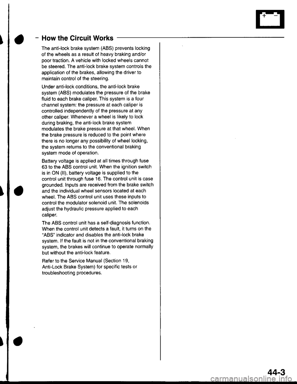
- How the Circuit Works
The anti-lock brake system (ABS) prevents locking
of the wheels as a result of heavy braking and/or
poor lraction. A vehicle with locked wheels cannot
be steered. The anti-lock brake system controls the
application of the brakes, allowing the driver to
maintain control of the steering.
Under anti-lock conditions, the antilock brake
system (ABS) modulates the pressure of the brake
tluid to each brake caliper. This system is a four
channel system: the pressure at each caliper is
controlled independently of the pressure al any
other caliper. Whenever a wheel is likely to lock
dunng braking, the anti-lock brake system
modulates the brake oressure at that wheel. When
the brake pressure is reduced to the point where
there is no longer any possibility of wheel locking,
the system returns to the conventional braking
system mode of operation.
Battery voltage is applied at all times through fuse
63 to the ABS control unit. When the ignition switch
is in ON (ll), battery voltage is supplied to the
control unit through fuse 16. The control unit is case
grounded. Inputs are received from the brake switch
and the individual wheel sensors located at each
wheel. The ABS control unit uses these inputs to
control the modulator solenoid unit. The solenoids
adjust the hydraulic pressure applied to each
calioer.
The ABS control unit has a self-diagnosis function.
When the control unit detects a fault, it turns on the"ABS" indicator and disables the anti-lock brake
system. lf the fault is not in the conventional braking
system, the brakes will continue to operate normally
but without the anti-lock feature.
Refer to the Service Manual (Section '19,
Anti-Lock Brake System) for specific tests or
troubleshooting procedures.
44-3
Page 2110 of 2189
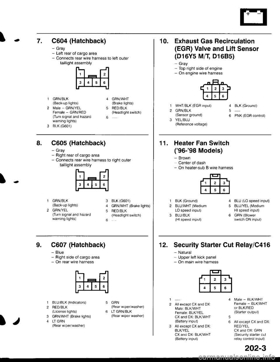
\7. C604 (Hatchback)
GRN/BLK(Back-up lights)
l\4ale GRNIYELFemale - GRN/RED(Turn signaland hazardwarning lights)
BLK (G601)
- Gray- Left rear ol cargo area- Connects rear wire harness to left outer
taillight assembly
4
5
6
1
2
GRNAVHT(Brake lights)
FED/BLK(Headllght switch)
10. Exhaust Gas Recirculation
(EGR) Valve and Lift Sensor
1
2
3
(D16Y5 MfI D1685)
- Gray- Top right side of engine- On engine wire harness
WHT/BLK (EGR input)
GRN/BLK(Sensor ground)
YEUBLU(Reference voltage)
4
5
6
BLK (Ground)
PNK (EGR control)
of cargo area
rear wire harness to right outer
assembly
n- -n
a t | _ a2a
l3I4t5tttl
IJ
I
8. C605 (Hatchback)
- Gray- Right rear- Connects
taillight
GRN/BLK(Back-up lights)
GRNTYEL(Turn signaland hazardwarning lights)
3
4
5
6
1
2
BLK (G601)
GFNAVHT (Brake lights)
RED/BLK(Headlight switch)
11. Heater Fan Switch
('96-'98 Models)
- Brown
Center of dash- On heater-sub B wire harness
BLK (Ground)
BLUAVHT (L4edium
LO speed input)
BLU/BLK(Hl speed input)
4
5
6
1
2
3
BLU (LO speed input)
BLU/YEL (Medium
Hlspeed input)
GFIN (Blowerswitch ON input)
9. C607 (Hatchback)
- Blue- Right side o{ cargo area- On rear wire harness
BLU/BLK (lndicators)
RED/BLK(License lights)
GBN,ryVHT (8rake lights)
LT GBN(Rear wiper/washe0
5
6
1
2
3
4
GRN(Rear wiper/washer)
LT GRN/BLK(Rear \/iper washer)
)/
202-3
12. Security Starter Cut Relay/C416
- Natural* Upper left kick panel- On main wire harness
1
2Allexcept CX and DXI[,4ale: BLK,^r'r'HTFemale: BLKI/ELCX and DXi BLI(WHT(Battery input)
All except CX and DX:BLK^/ELCX and DX: BLK/WHT(Baftery input)
[.4ale - BLK/WHTFemale - BLKAVHTor BLKRED(Starter output)
All excepi CX and DX:RED/YELCX and DX: GRN(Security starter c!1relay control inpul)
5
6
tl3'
Page 2137 of 2189
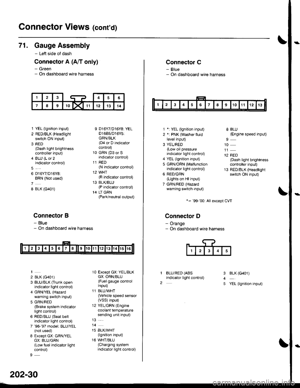
Connector Views (conrd)
71. Gauge Assembly
- Left side of dash
Connector A (A/T only)
- Green- On dashboard wire harness
1 YEL (lgnition input)
2 RED/BLK (Headlight
switch ON input)
3 RED(Dash light brightnesscontroller input)
4 BLU (L or 2indicator control)
6 D16Y7/D16Y8:BRN (Not used)
8 BLK (G401)
Connector B
- Blue- On dashboard wire harness
2 BLK (G401)
3 BLU/BLK (Trunk openindicator light control)
4 GRN/YEL (Hazard
warning switch input)
5 GRN/RED(Brake system indicatorlight control)
6 RED/BLU (Seat beltindicator light control)
7 '96-'97 model: BLU,ryEL(not used)
8 Except GX: GRN/YELGX: 8LU/GRN(Low fuel indicator lightcontrol)
9 D16Y7/D16Y8: YEL01685/016Y5:GRN/BLK(D4 or D indicatorcontrol)
10 GRN (03 or Sindicator control)
11 RED(N indicator control)
12 WHT(F indicator control)
13 BLI(BLU(P indicator control)
14 LT GBN(Park/neutral output)
10 Except GX: YEUBLKcX: ORN/BLU(Fuel gauge controlinput)
11 BLUAVHT(Vehicle speed sensor(VSS) input)
12 YEUGRN (Engine
coolant temperaturesending unit input)
14
15 BLI(IVHT(lgnition input)
16 WHT/BLU(Charging systemindicator light control)
202-30
Connector C
- Blue- On dashboard wire harness
1 *: YEL (lgnition input)
2 *: PNK (Washer lluidlevel input)
3 YEUBED(Low oil pressureindicator light control)
4 YEL (lgnition input)
5 GRN/ORN (Malfunctionindicator light control)
6 RED/GRN
{Lights on Hl input)
7 GBN/RED (Hazardwarning switch input)
*= '99-'00: All except CVT
Connector D
- Orange- On dashboard wire harness
BLU/RED (ABS
indicator light control)
8 BLU(Engine speed input)
10
12 FED(Dash light brightnesscontroller input)
13 RED/BLK (Headlightswitch ON input)
I
2
3
4
5
BLK (G401)
YEL (lgnition input)
Page 2159 of 2189
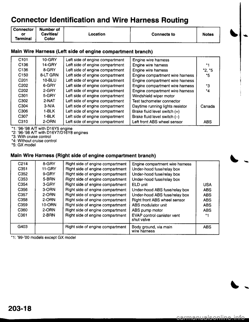
Connector ldentification and Wire Harness Routino
Connector
or
Terminal
Number ot
Cavities/
Color
LocationConnects toNotes
Main Wire Harness (Left side of engine compartment branch)
c101
cI36
c136
c150
c201
c202
c202
c301
c302
c304
UOUO
c307
c310
1O.GRY
14-GRY
8.GRY
8.LT GRN
1O-BLU
6.GRY
2-GRY
5.GRY
2.NAT
3-N/A
1.BLK
1-BLK
2.ORN
Left side ot engine compartment
Left side of engine compartment
Letl side of engine compartment
Lett side of engine compaftment
Left side of engine compartment
Left side of engine compartment
Left side of engine compartment
Left side of engine compartment
Left side of engine compartment
Left side of engine compartment
Left side of engine compartment
Left side of engine compartment
Left side of engine compartment
Engine wire harness
Engine wire hamess
Engine wire hamess
Engine compartment wire harness
Engine compartment wire harness
Engine compartment wire harness
Engine compartment wire harness
Windshield wiper motor
Test tachomeier connector
Daytime running lights resistor
Brake fluid level switch (+)
Brake fluid level switch (-)
Left front ABS wheel sensor
.1
'r.q
r5
.4
Canada
ABS
.1 : '96-98 A/T with D16Y5 enoine'2: '96-98 A,/T with D16Y7/D16Y8 enoines.3: With cruise control*4: Without cruise control.5: GX model
Main Wire Harness (Right side of engine compartment branch)
c214
c351
wacl
UJCJ
c356
c357
c358
UOCY
c360
c361
8-GRY
11.GRY
9.GRY
5-BRN
3-GRY
3-ORN
2.ORN
2-ORN
10-oRN
2.ORN
2-8RN
Right side of engine compartment
Right side of engine compartment
Right side of engine compartment
Right side of engine compartment
Right side of engine compartment
Right side of engine comparlment
Right side ot engine compartment
Right side ot engine companment
Right side of engine compartment
Right side of engine compartment
Right side of engine compartment
Engine compartment wire hamess
Under-hood fuse/relay box
Undef-hood tuse/relay box
Under-hood fuse/relay box
ELD unit
Under-hood ABS fuse/relay box
Underhood ABS fuse/relay box
Right front ABS wheel sensor
ABS modulator unit
ABS pump motor
EVAP control canister vent
shut valve
USA
ABS
ABS
Al'D
AE5
ABS-1
G403Bight side of engine compartmentBody ground, via mainwtre narnessABS
.1: '99-'00 models except GX model
203-18