Page 1701 of 2189

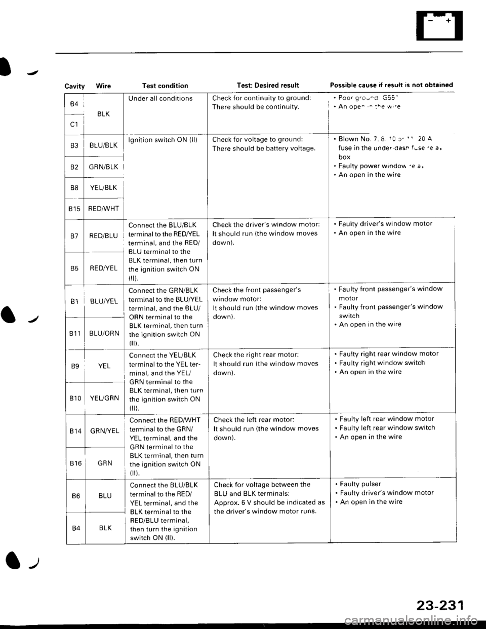
CavityWireTest conditionTest: Desired resultPossible caus! d r"suh rs nol obtrincd
to:
c1
BLK
UnderallconditionsCheck for continuity to groundl
There should be continuity., An ope^ ^ :he tt .e
. Blown No.7.6 10 r' " 20 A
fuse in the unde. oast f.se 'e a,
box. Faulty power windo$ 'e a,. An open in the wire
B3BLU/BLKlgnition switch ON (ll)Check for voltage to grou nd:
There should be battery voltage.
B2GRN/BLK
YE L/BLK
R EDA/VHT815
81RED/BLU
RED/YEL
Connect the BLU/BLK
terminal to the RED/YEL
terminal, and the RED/
BLU terminal to the
BLK terminal, then turn
the ignition switch ON
1I i.
Check the driver's window motorl
It should run (the window moves
oown).
. Faulty driver's window motor
. An open in the wire
B1BLUIVEL
Connect the GRN/BLK
terminal to the BLU|YEL
terminal, and the BLU/
Check the front passenger's
wrnoow motor:
It should run (the window moves
Fau lty front passenger's window
motor
Faulty front passenger's window
An open in the wire
811BLU/ORNBLK terminal, then turn
the ignition switch ON
0 r).
B9YEL
connect the YEL/BLK
terminal to the YEL ter-
minal, and the YEU
GRN terminal to the
BLK terminal, then turn
the ignition switch ON
0 r).
Check the right rear motor:
It should run (the window moves
down).
Fauity right rear window motor
Fau lty right window switch
An open in the wire
Bt0YEUGRN
814GRNI/EL
connect the RED,ryVHT
terminal to the GRN/
YEL terminal, and the
GRN terminal to the
BLK terminal, then turn
the ignition switch ON
0 r).
Check the left rear motor:
It should run (the window moves
Faulty left rear window motor
Faulty left rear window switch
An open in the wire
816GRN
B6BLU
Connect the BLU/BLK
terminal to the RED/
YEL terminal, and the
BLK terminal to the
RED/BLU terminal,
then turn the ignition
switch ON (ll).
Check for voltage between the
BLU and BLK terminalsl
Approx. 6 V should be indicated as
the driver's window motor runs.
Faulty pulser
Faulty driver's window motor
An open in the wire
B4BLK
23-231
Page 1702 of 2189
Power Windows
Passenger's Window Switch Test
Coupo/H8tchback:
1. Remove the armrest pocket from the door panel
{see section 20}.
5P CONNECTOR
2. Disconnect the 5P connector from th€ passenger's
window switch.
Sodan:
1. Remove the armrest (see section 20).
Disconnect the 5P connector, then .emove the mount-
ing screw from the passenge/s switch.
PASSENGER'S WINDOW SWITCH
5P CONNECTOR
23-232
Switch sids of 5P t.rminal:
Terminal side olmale terminals
Check for continuity between the terminals in each
switch position according to the table.
12a5
Terminal
il;--lI25
UP
-o
-o
OFF
-o
o--o
DOWNo--o
Page 1705 of 2189
Moonroof
a-/
Component Location Index
MOONBOOF SWITCHTest, page 23-236
. MOONROOF CLOSE RELAYlwire colors: WHT. GRN/YEL, lIGRN/oBN, BLK, and GRN/REDITest, page 23 87, 88. MOONROOF OPEN RELAY
f wire colors: WHT, cRN/RED,l
IGBN/ORN, BLK and YEL lTest, page 23'87, 88
MOONROOF MOTORTest, page 23-236
l-,
23-235
Page 1706 of 2189
Moonroof
Circuit Diagram
JNDEB.FOOD FUSE qELAY BOX
*1 96 97 modes:+2 r '98-00 models
OPEN/CLOSE SWITCHI.ourrE lhe lifino ooglalron{T[!b - F! ycto6ed)A and C lerminals are connecled.. ourno lhe sldno o$ralron(Fully?osed *: Futly op€n)A and Blermrnals are connecled.
TILT/CLOSE SWITCHI. Durinq lhe lihina oDeralion[Ir]t uir - Fillyc osed)D and F terninaliare conned€d.. Durino lhe slidrno oDoratonlFulv dossd --: Fllv ooenl0 anil E lemnals are (inhecied.
IGNITION SWTCH
BLK
I_lr--
G40tG402
MOONFOOF SWITCH
23-236
Page 1707 of 2189

Funstion Test
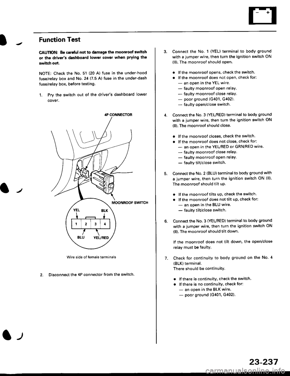
CAUTION: Bo careful not to damago the moonroof switch
or ths driv6r's dashboard lowsr cover when prying the
3witch out.
NOTE: Check the No. 51 (20 Al fuse in the under-hood
tuse/relay box and No.24 (7.5 A) fuse in the under-dash
fuse/relay box, before testing.
1. Prv the switch out of the driver's dashboard lower
cover.
swtTcH
Wire side of female terminals
2. Disconnect the 4P connector from the switch
4P CONNECTOR
l-t
23-237
Connect the No. 1 (YELI terminal to body ground
with a jumper wire, then turn the ignition switch ON
(ll). The moonroof should open.
. lf the moonroot opens, check the switch.
. lf the moonroot does not open, check for:
- an open in the YEL wire.
- faulty moonroof open relay.
- faulty moonroof close relay,
- poor ground (G401, G402).- fa u lty open/close switch.
Connect the No. 3 (YELnED) terminal to body ground
with a jumper wire. then turn the ignition switch ON
(ll). The moonroof should close.
. lf the moonroof closes. check the switch.
. lf the moonrool does not close, check for:
- an open in the YEURED or GRN/RED wire'
- faulty moonroof close relaY.
- faulty moonroot oPen relaY.
- faulty tilvclose switch.
Connect the No. 2 (BLU) terminal to body ground with
a jumper wire, then turn the ignition switch oN (ll).
The moonroof should tilt up.
. lf the moonroof tilts up, checkthe switch.
. lf the moonroof does nottilt up, checkfor:
- an open in the BLU wire.
- taulty tilvclose switch
Connect the No. 3 (YEURED) terminal to bodY ground
with a jumper wire, then turn the ignition switch ON
(ll), The moonroof should tilt down.
lf the moonroof does not tilt down, the open/close
relay must be taulty.
Check for continuity to body ground on the No. 4
{BLK}terminal.
There should be continuity.
. lf there is continuity, check the switch
. lf there is no continuity, check for:
- an open in the BLK wire
- poor ground (G401, G402).
6.
7.
Page 1708 of 2189
Moonroof
1.
Switch Test
Carefully remove the switch from the driver's dash-
board lower cover {see page 23-205}.
Check for continuitv between the terminals in each
switch position according to the table.
Terminal
t*',*-----__\I234
ut-t-
OPENo--o
CLOSEo---o
TILTo--o
23-234
Motor Test
'1.Remove the headliner (see section 20).
Disconnect the 2P connector from the moonroof
motor.
Terminal side of male terminals
Check the motor by connecting power and ground
according to the table.
4. lf the motor does not run, replace it (see section 20).
NOTE: See Closing Force Check in section 20 for
motor clutch test.
\_____lTr1
Position
,l
OPENo@
CLOSE@
Page 1709 of 2189
Open/Close-Tilt/Close Switch Test
1. Remove the headliner (see section 20).
2. Disconnect the 2P and 4P connectors from the moon-
roof motor and the switch.
3. Check for continuity between the terminals in each
switch position according to the table.
Terminal side of male terminals
Terminal
*r*"-
-\123
CLOSE .* TILTo--oo---o
CLOSE ..--. OPENo--o
4. lf there is no continuity, adiust or replace the switch'
l-t
23-239
Page 1710 of 2189
Gruise Control
Component Location Index
MAIN SWITCHTesVReplacement,page 23-242CABLE REELReplacement, section 24
BRAKE SWITCH, fest, page 23-244. Pedal Height Adjustment,section 19CRUISE CONTROI. UNITInput Test, page 23-240
swrTcH {M/T). Test. page 23-244. Clutch Pedal Adjustment,section 12
atfSWTTCH. Test, page 23-154' Replac€ment, page 23-'155
ACTUATOR CABLEAdjustment, page 23-246
VACUUM TANK
TOR ASSEMBLY. Test, pag€ 23-245. Replacement, page 23-246. Solenoid Test, page 23-247' Disassembly, page 23-248
23-240