2000 HONDA CIVIC transmission oil
[x] Cancel search: transmission oilPage 871 of 2189

Continuously Variable Transmission (CVTI
Special Tools ................ 14-194
Description .................... 14-195
Clutches/Reverse Brake/Planetary
Gear/Pulleys .......... 14-198
power Flow ..............,..... 14-200
Electronic Control SYstem(,96 - 98 Modets) ......14-203
Electronic Control System
('99 - oo Models) " 14-205
Hydraulic Control '....... 14-208
Hydraulic Flow .'..-.....'... '14-212
Park Mechanism .....-...'.' 14-222
Eleqtrical Systom
Component Locations'96 - 98 Models """"""' 14-224,99 - 00 Modets ............. 14-225
TCM Circuit Diagram ('96 - 98 Models) ............. 14-226
TCM Terminal Voltage/Measuring Condiiions ('96 - 98 Models) '.... 14-228
PcM Circuit Oiaqram{A/T Control System: '99 - 00 Models} ...--.... 14-230
PCM Terminal Voltage/Measuring Conditions('99 - 00 Models)
A/4 Control System .'.'...14-232
Troubleshooting Procedures ... . .... .....',........."' '14-234
Symptom-to-ComPonent Chart
Electrical System - '96 - 98 Models ......'..... '14-234
Electrical System -'99 - 00 Models ..'....-..-. '11-210
Electrical Troubleshooting
Troubleshooting Flowcharts('96 - 98 Models) """'11-242
Troubleshooting Flowchart
('99 - 0O Modets) ...... 14-265
Linear Solenoids/lnhibitor Solenoid
Test ......................... . ...... 14-29f
Drive Pulley/Driven Pulley/Secondary Gear
Shaft Speed Sensors
Replacement .........'...... .14-292
Start Clutch Control
Start Clutch Calibration Procedure ....... ....,. 14-293
Hydraulic SYstem
Symptom-to-ComPonent Chart
Hydraulic System '.'.......14-294
Road Test ............................ 14-296
Stall Speed
Test......................... ...... 14-294
Fluid Level
Checking/Changing ....... 14-299
Pressure Testing ................. 14-300
Lower Valve BodY AssemblY
Replacement ..........,... 14-302
ATF Filter
Removal/lnstallation ..... 14-303
Transmission
Transmission
Removal ........... . 14-304
lllustrated Index
Transmission/Lower Valve BodY
Assembly ................. 14-308
Transmission Housing/Flywheel Housing ... 14-310
End Cover/f ntermediate Housing ..........'.'.... 14-312
Transmission Housing/Lower Valve Body Assembly
Removal ..........'.... .. " 14-314
Transmission Housing/Flywhesl Housing
Removal ................. ........ 1+316
End Cover/lntermediate Housing
14-318Removal .........,...............
Manual Valve Body
Disassembly/lnspection/Reassemblv .'.'.'..... 1 4-320
Forward Clutch
lltustrated Index ........................................ 14-321
Disassemblv .................. 14-322
Reassemblv , ,, . ',','......14-324
Secondary Gear Shaft
25 x 35 mm Thrust Shim Selection ..'.'....-... 14-324
Differential
lllustrated lndex ...,.....................,.,...-.-.-...'... 14-329
Backlash Inspection .-....14-329
Bearing Replacement ......'........'....'... ....'... 14-330
Differential Carrier Replacement ........'........ 14-330
Oil Seal Removal ........... 14-331
Oil Seal Installation/Side Clearance ....... . . 14-331
Flywheel Housing Input Shaft Oil Seal
Replacement .....,.... ...'.'.. 14-333
Transmission Housing Bearings
Driven Pulley Shaft Bearing
Replacenient ...................'. . ...................'.. 14-334
Secondary Gear Shaft Bearing
Reolacbment ...................... . .......... . ........ 14-335
Flywheel Housing Beating
Secondary Gear Shaft BearingReo1acement..................,........................... 14-335
Ring Gear Bearing
Replacement......... ........ 14-336
Control Shaft Assembly
Removal/lnstallation ....................'........... 14-336
Transmission
Reassembly .................. 14-338
Flywheel/Drive Plate .. . ...... . ...... ... . ....-.....'.'...14-341
Transmission
lnstalation ..................... 14-348
Cooler Flushing .'......... 14-352
shift cable
Removal/lnstallation....'........." """ 14-354
Adjustment .......'........ 14-355
Shift Lever ........................,. 14'356
Shift Indicator Panel
Adjustment ................ 14-357
ATF Cooler/Hoses
lnsta llation ......,,...... .... 14-357
Page 977 of 2189
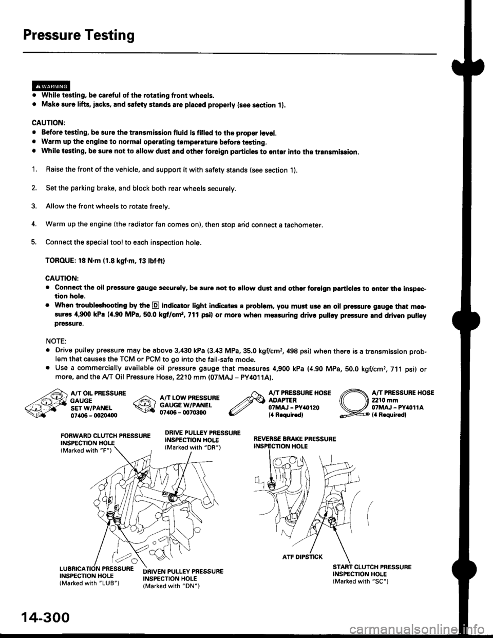
Pressure Testing
. While testing, be careful of the rot8ling front wheels.
. M8k6 suro lifts, iacks, and satety stands are placed properly lsee section 11.
CAUTION:
. Before testing, be sur. the transmb3ion fluid is fillod to the propor lcvel.. Warm up the engin€ to nolmal operating tsmperature bofore testing. While t€sting, be 3ure not to allow dust and other loreign particles to onler into the transmi$ion.
1. Raise the front of the vehicle, and support it with safety stands (see section 1).
2. Set the parking brake. and block both rear wheels securely.
3. Allow the front wheels to rotate freely.
4. Warm up the engine (the radiator fan comes on), then stop arid connect a tachometer.
5. Connect the special tool to each inspection hole.
TOROUE: 18 N.m (1.8 kgt'm, 13 tbtfr)
GAUTION:
. Connect the oil pressuro gauge !!€curoly, bs sur6 not to allow dust and other foroign particlG3 to ontar the inspsc-tion hole.
. Whon troubleshooting by tho E indicltor light indic.t6 a problam. you mu3t u3e an oil p.essure gluge that moa,sures 4,9(X) kPa (a.90 MPa,50.0 kS cr*,771psi) or more when molsuring driv. pulley pressure and driven pullcypre33ure.
NOTE:
. D.ive pulley pressure may be above 3,430 kPa (3.i8 MPa,35.0 kgf/cmr, 498 psi) wh€n there is a transmission prob-
lem that causes the TCM or PCM to go into the fail-safe mode,. Use a commercially available oil pressure gauge that measures 4,900 kPa {4.90 MPa, 5O.O kgf/cmr, 711 psi) ormore, and the Ay'T Oil Pressure Hose, 2210 mm (07MAJ - PY4011A).
FORWARD CLUTCH PRESSUREINSPECTION
lMarked with "F")
REVERSE BRAKE PRESSUREINSPECTION I.IOLE
A/T OIL PRESSUREGAUGESET W/PANEL0ta{r6 - oO2Oi|(Xt
A/T LOW PRESSUREGAUGE W/PANEL0706 - qt7o:t{ro
DRIVE PULLEY PRESSUREINSPECTION HOI.E(Marked with "DR")
A/T PRESSURE HOSEADAPTER07MAJ - PYar'120lil R.qulr.d)
A/T PRESSUBE HOSE2210 mm07MAJ - PYitollAla R.quir.d)
(
INSPECNON HOLE(Marked with "SC")
CLUICH PRESSURE
INSPECTION HOLE(Marked with "LUB")
DRIVEN PULLEY PRESSUREINSPECTION HOLElMarked with "DN")
14-300
ATF DIPSTICK
Page 983 of 2189

Transmission
Removal (cont'd)
10. Remove the cotte. pins and castle nuts, then separatethe ball joints from the lower arm (see section 1g).
SELF-LOCKING -=V,
NUT \Replace. oitupea rOax
Remove the right damper fork bolt, then separateright damper fork and damper.
Pry the right and left driveshafts out of the differen-tial.
Pull on the inboard joint to remove the right and leftdriveshafts (see section 16).
Tie plastic bags over the driveshaft ends.
NOTE: Coat all precision finished surfaces with cleanengine oil.
Remove the exhaust pipe A.
/\<,\CASTLE I{UT COTTERReplac6.
't 1.
't2.
tJ.
14.
q.
SELF.LOCKINGNUTReplace.
SELF.LOCKING NUTReplace.
14-306
EXHAUST PIPE A
19.
'16, Remove the right front mounvbracket,
ATF COOLER HOSE
17. Remove the ATF cooler hoses at the ATF coolerlines. Turn the ends of the ATF cooler hoses uo toprevent CVT fluid from flowing out, then plug theATF cooler hoses and lines,
NOTE: Check for any sign of leakage at the hosejoints.
18. Remove the engine stiffeners and the flywheel cover.
Remove the eight drive plate bolts one at time whilerotating the crankshaft pullev.
ENGINE STIFFENER
Page 1008 of 2189
l.
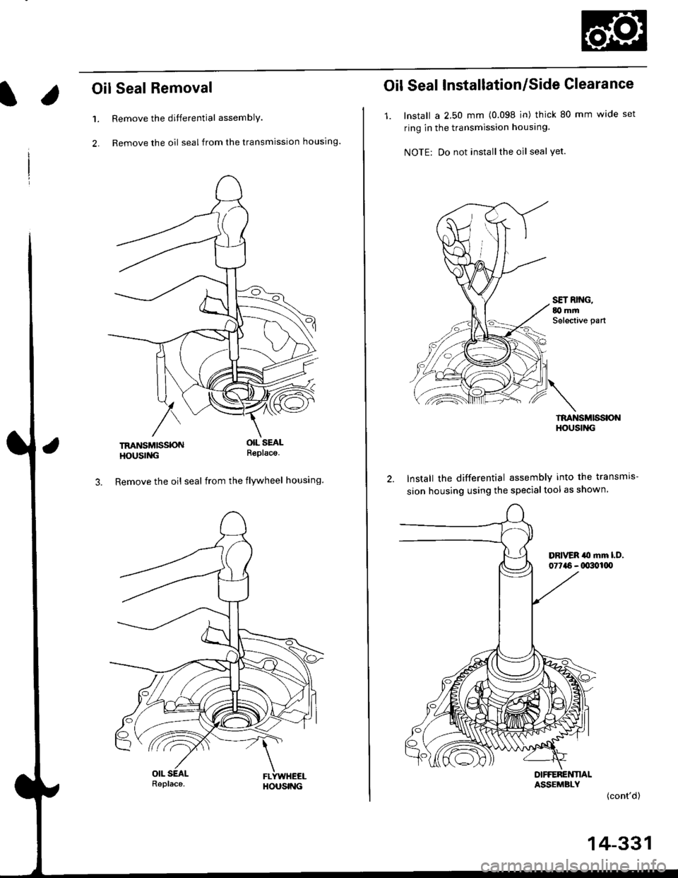
Oil Seal Removal
Remove the differential assembly.
Remove the oil seal from the transmission housing.
1.
2.
TRANSMISSONHOUSING
OIL SEALR€placa.
3. Remove the oil seal from the flywheel housing.
Oil Seal Installation/Side Clearance
1. lnstall a 2.50 mm (0.098 in) thick 80 mm wide set
ring in the transmission housing.
NOTE: Do not installthe oil seal yet.
TRANSMISSIONHOUStl{G
lnstall the differential assembly into the transmrs-
sion housing using the specialtool as shown
DIFFEREI{NALASSEMBLY(cont'd)
14-331
Page 1010 of 2189
Flywheel Housing
Input Shaft Oil Seal
l.
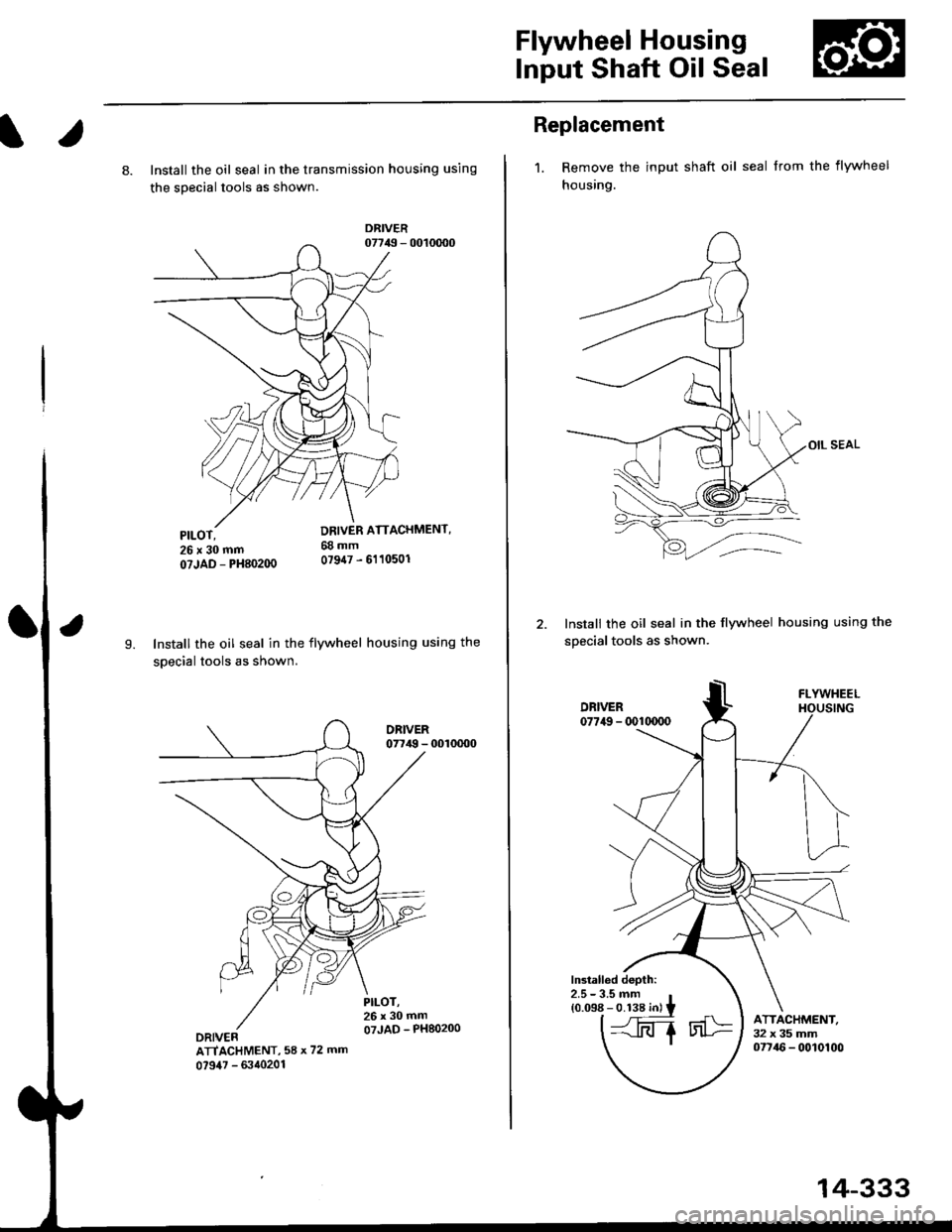
8. Install the oil seal in the transmission housing using
the sDecial tools as shown.
DRIVER07749 - 0010d)0
9.Install the oil seal in the flywheel housing using the
soecial tools as shown.
PILOT,26x30mmoTJAD - PH80200DRIVERATIACHMENT, 58 x 72 rnin
0?947 - d'40201
Replacement
1. Remove the input shaft oil seal from the flywheel
housing.
OIL SEAL
Instali the oil seal in the flywheel housing using the
soecialtools as shown.
FLYWHEEL
lmtalled depth:2.5- 3.5 mmro"nri':,ilii.rl
t@
14-333
Page 1052 of 2189
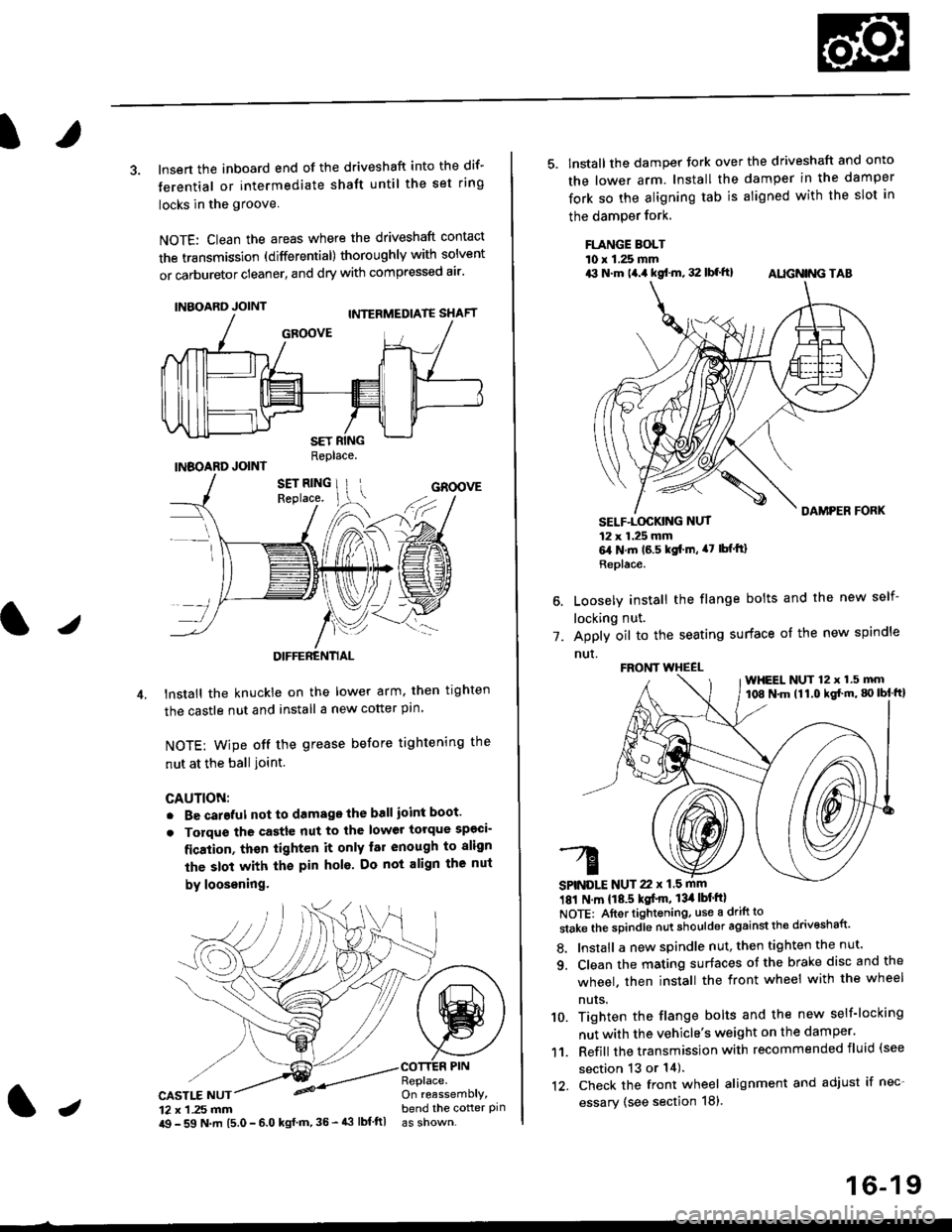
3. lnsert the inboard end of the driveshaft into the dif-
terential or intermediate shaft until the set ring
locks in the groove
NOTE: Clean the areas where the driveshaft contact
the transmission (differential) thoroughly with solvent
or carburetor cleaner, and dry with compressed air'
INBOARD JOINT
INBOARD JOINTReplace.
GROOVE
an
DIFFERENTIAL
lnstall the knuckie on the lower arm. then trghten
the castle nut and install a new cotter pin
NOTE: wipe off the grease before tightening the
nut at the ball ioint.
CAUTION:
. Be careful not to damago the ball ioint boot'
. Torque the castle nut to the lower torque sp€ci-
fication, thsn tighten it only far enough to align
the slot with th€ pin hol6. Do not align the nut
by loosening.
CASTLE NUT12 x 1 .25 mm
COTTER PINReplace.On reassemblY,bend the cotter pinJi$ - 59 N.m 15.0 - 6.0 kgl m,35 - 43 lbf ftl
16-19
5. lnstall the damper tork over the driveshaft and onto
the lower arm. Install the damper in the damper
fork so the aligning tab is aligned with the slot in
the damPer fork.
FLANGE BOLTl0 r 1.25 mmrit N.m t4.a kgf.m, 32 lbf.ft) AIIGN|NG TAB
1.
SELF-LOGKING NUT12 x 1.25 mm6,1N.m 16.5 kgi.m, a7 lbfftl
Replace.
Loosely install the flange bolts and the new self-
locking nut.
Apply oil to the seating surface of the new spindle
nut.
181 N m 118.5 kgt'm, 13il lbt'ftl
NOTE: Aftortightening, use a drift to
stake the spindle nut shoulder against the drivoshaft'
8. Install a new spindle nut, then tighten the nut'
9. Clean the mating surfaces ot the brake disc and the
wheel. then install the front wheel with the wheel
nuts.
10. Tighten the flange bolts and the new self-locking
nut with the vehicle's weight on the damper.
11. Refill the transmission with recommended fluid (see
section 13 or 14).'t2. Check the front wheel alignment and adjust if nec-
essary (see section 18),
FRONT WHEEL
SPINDLE NUT 22 x 1.5 mm
WHEEL NUT 12 x 1.5 mm108 N.m (11.0 kgl'm, g) lbl ftl
Page 1053 of 2189
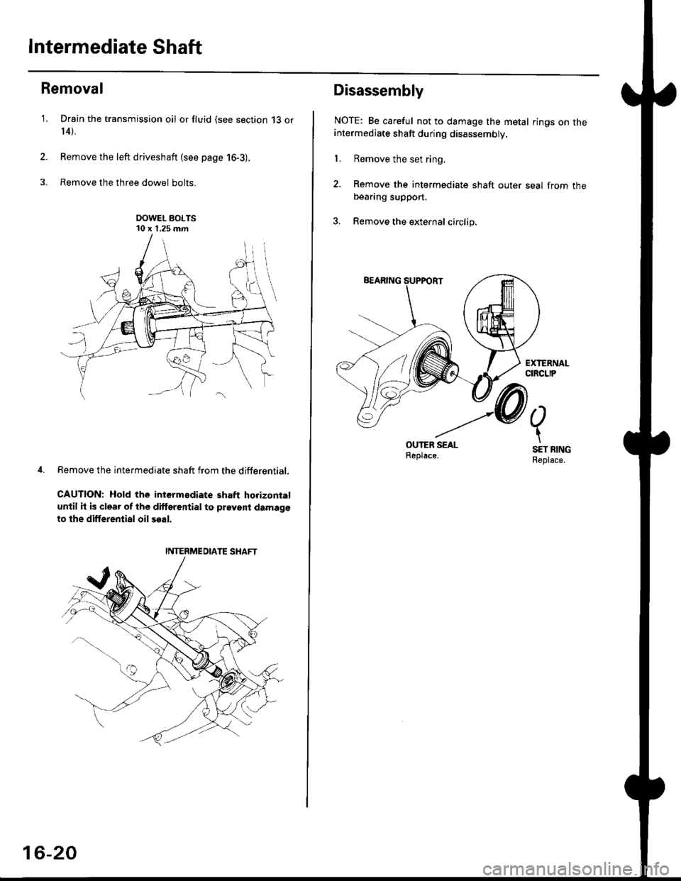
Intermediate Shaft
Removal
Drain the transmission oil or fluid {see section 13 or
r 4).
Remove the left driveshaft (see page 16-3).
Remove the three dowel bolts.
OOWEL BOLTS'10 x 1.25 mm
Remove the intermediate shaft from the differential.
CAUTION: Hold the intermsdiate shaft horizontal
until it is clear of lhe dilterential to prevent damage
to the differential oil seal.
'1.
2.
3.
INTERMEDIATE SHAFT
16-20
Disassembly
NOTE: Be careful not to damage the metal rings on theintermediate shaft during disassembly.
1. Remove the set ring.
2. Remove the intermediate shaft outer seal from theDeaflng suppon.
3. Remove the external circlip,
Page 1056 of 2189
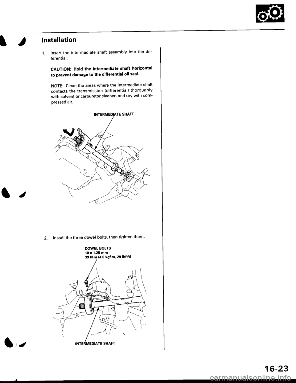
lnstallation
1. lnsert the intermediate shaft assembly into the dif-
ferential.
CAUTION: Hold the intermodiate shaft horizontal
to prevent damag€ to the difterential oil seal'
NOTE: Clean the areas where the intermediate shaft
contacts the transmission (differential) thoroughly
with solvent or carburetor cleaner, and dry with com-
Dressed air,
2. Install the three dowel bolts, then tighten them'
DOWEL BOLTS10 x 1.25 mm39 N.m {i1.0 kgf'm, 29 lbf'ftl
lz
16-23