2000 HONDA CIVIC light
[x] Cancel search: lightPage 2034 of 2189
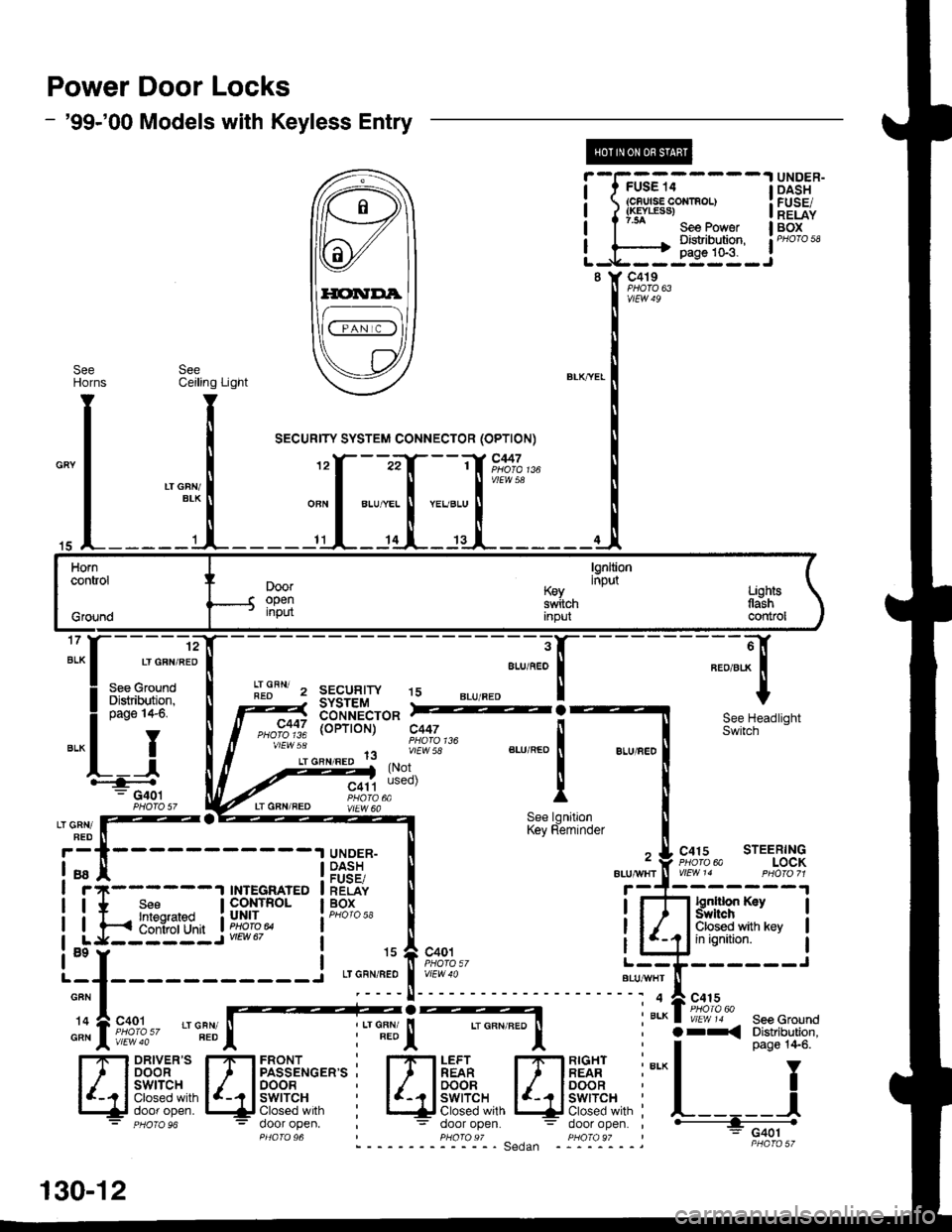
Power Door Locks
- '99-'00 Models with Keyless Entry
@
i-f?G;.-----l
i ?f*""t:::", i
L-,H-i{*q-J
UNDER-DASHFUSE/RELAYBOX
8 Y C419
vtEW49
SeeHOrns
15
Horncontrol
Grgund
lgnltioninputDooropeninput
K€yswitchInpul
Lighlstlashcontrol
17
ALK
c447
vtEw 5a
'12
LT GFN/RED
See GroundDistribution,page I +6,
YI
IF--.--.r-G401
I
3
ALU/f,EO
!r.lFN' z sEcuglw t5REOSYSTEMtsb'*nii'cro* =2
a, o"nt"ao 1lvlEw 58
(Not
(oPTroN) c447See HeadlightSwitch
C415 STEERINGPHora 6a LOCKVlEtt\/ 14 PHO|O 71
lgntlion KaySYrftchClosed with keyin ignition.
LT GRN/FED
LT GFN/REDSee lgnitionKey Reminder
UNDER-DASHFUSE/RELAYBOX
ALU/IVITT
a9
GFN
'14
GRN
130-12
Page 2037 of 2189
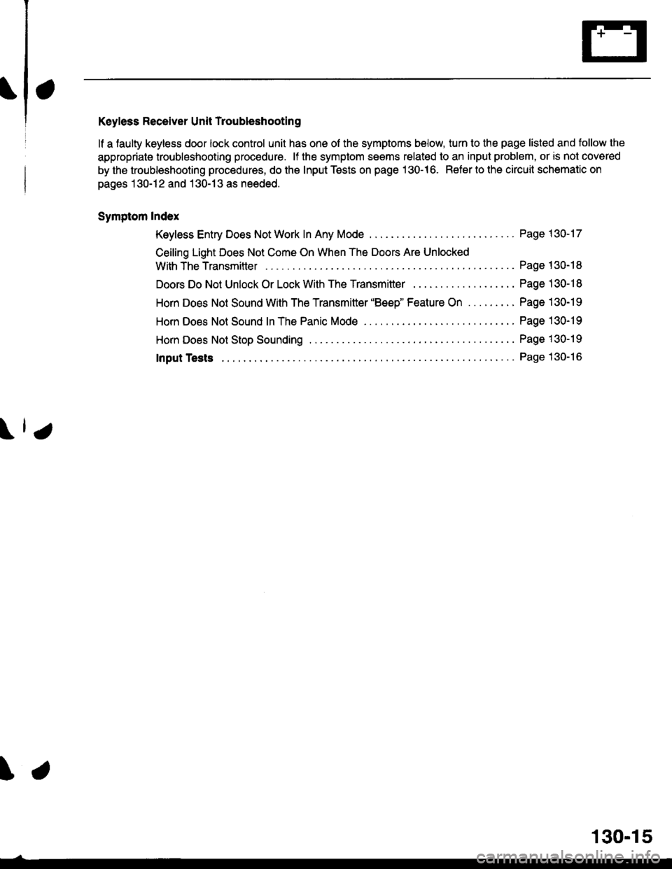
Keyless Receiver Unit Troubleshooting
lf a faulty keyless door lock control unit has one of the symptoms below, turn to the page listed and tollow the
appropriate troubleshooting procedure. lf the symptom seems relatod to an input problem, or is not covered
by the troubleshooting procedures, do the Input Tests on page 130-16. Refer to the circuit schematic on
pages 130-12 and 130-13 as needed.
Symptom Index
Keyless Entry Does Not Work In Any Mode
Ceiling Light Does Not Come On When The Doors Are Unlocked
With TheTransmitter ....
Doors Do Not Unlock Or Lock With The Transmitter . .
Horn Does Not Sound With The Transmitter 'Beep" Feature On .........
Horn Does Not Sound In The Panic Mode ..
HornDoes NotStopSounding ...............
Page 1 30-17
Page 130- 18
Page 130-1 I
Page 130-19
Page 130-19
Page 1 30-19
Page 130-16Input Tests
\.
130-15
Page 2038 of 2189
Power Door Locks (cont'd)
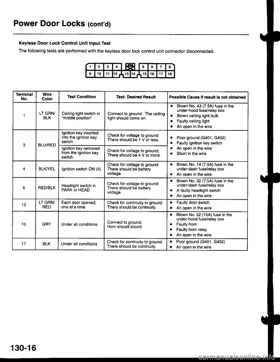
Keyless Door Lock Control Unit Input Test
The following tests are performed with the keyless door lock control unit connector disconnected.
TerminalNo.WireColorTest ConditionTest: Desir€d ResultPossible Cause if result ls not obtain€d
1LT GRN/BLKCeiling light switch in"middle position"Connect to ground: The ceilinglight should come on.
aBlown No. 43 (7.5A) luse in theunder-hood tuse/relay box
Blown ceiling light bulb
Faulty ceiling light
An open in the wire
o
a
a
3BLU/RED
lgnition key insertedinto the ignition keyswitch
Ch€ck lor voltage to ground:There should be I V or less.aPoor ground (G401, G402)
Faulty ignition key switch
An open in the wire
Short in the wire
a
a
o
lgnition key removedlrom the ignition keyswitch
Check for voltage to ground:There should be 4 V or more.
BLfiEtlgnition switch ON (ll)Check lor voltage to ground:
There should be batteryvoltage.
. Blown No. 14 (7.54) fuse in theunder-dash fuse/relay box
. An open in the wire
bREO/BLKHeadlight switch inPARK OT HEAD
Check for voltage to ground:
There should be batteryvoltage.
aBlown No. 32 (7.5A) luse in theunder-dash fuse/relay box
A faulty headlight switch
An open in the wire
a
o
LT GRN/RED
Each door opened,one at a timeCheck lor continuity to ground:
There should be continuitv.
oFaulty door switch
An open in the wireo
15GRYUnder all conditionsConnect to ground:
Horn should sound.
. Blown No. 52 (154) fuse in theunder-hood fuse/relay box
. Faulty horn
. Faulty horn relay
o An open in the wire
BLKUnder all conditionsCheck lor continuity to ground:
There should be continuity.
aPoor ground (G401 , G402)
An open in the wirea
130-16
Page 2040 of 2189
Power Door Locks (cont'd)
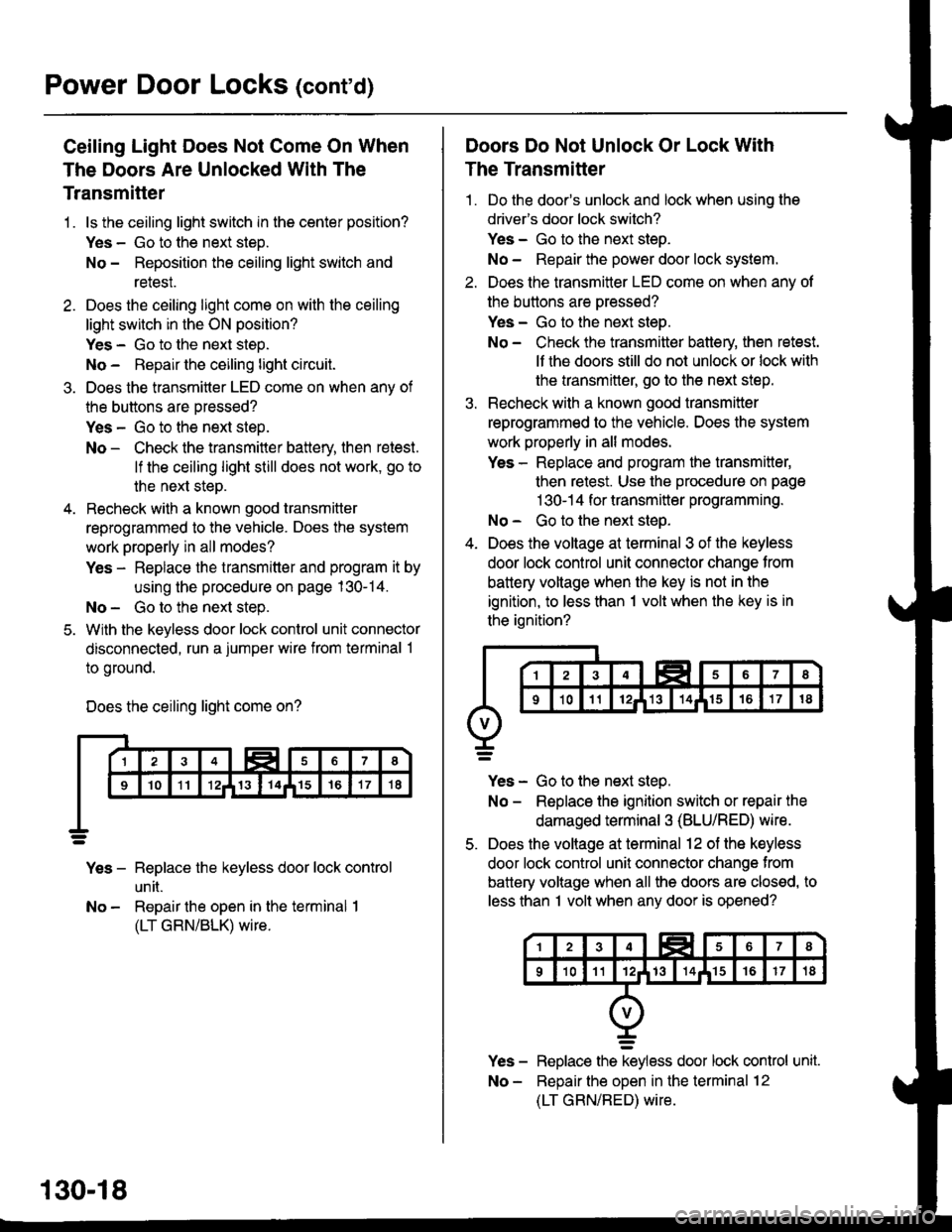
Ceiling Light Does Not Come On When
The Doors Are Unlocked With The
Transmitter
1 . ls the ceiling light switch in the center position?
Yes - Go to the next steD.
No - Reposition the ceiling light switch and
relesI.
2. Does the ceiling light come on with the ceiling
light switch in the ON position?
Yes - Go to the next steo.
No - Repau the ceiling light circuit.
3. Does the transmitter LED come on when anv of
the buttons are oressed?
Yes - Go to the next step.
No - Check the transmitter battery, then retest.
lf the ceiling light still does not work, go to
the next step.
4. Recheck with a known good transmitter
reprogrammed to the vehicle. Does the system
work properly in all modes?
Yes - Replace the transmitter and program it by
using the procedure on page 130-14.
No - Go to the next step.
5. With the keyless door lock control unit connector
disconnected, run a jumper wire from terminal 1
to ground.
Does the ceiling light come on?
Yes - Replace the keyless door lock control
un [.
No - Repair the open in the terminal I
(LT GRN/BLK) wire.
130-18
Doors Do Not Unlock Or Lock With
The Transmitter
1 . Do the door's unlock and lock when using the
drivefs door lock switch?
Yes - Go to the next steo.
No - Repair the power door lock system.
2. Does the transmitter LED come on when anv of
the buttons are oressed?
Yes - Go to the next steo.
No - Check the transmitter batlery, then retest.
lf the doors still do not unlock or lock with
the transmitter, go to the next step.
3. Recheck with a known good transmitter
reprogrammed to the vehicle. Does the system
work properly in all modes.
Yes - Replace and program the transmitter,
then retest. Use the procedure on page
1 30-1 4 for transmitter programming.
No - Go to the next steo.
4. Does the voltage at terminal 3 of the keyless
door lock control unit connector change from
battery voltage when the key is not in the
ignition, to less than 1 volt when the key is in
the ignition?
Yes - Go to the next step.
No - Replace the ignition switch or repair the
damaged terminal 3 (BLU/RED) wire.
5. Does the voltage at terminal 12 of the keyless
door lock control unit connector change from
battery voltage when all the doors are closed, to
less than I volt when any door is opened?
Replace the keyless door lock control unit.
Reoair the ooen in the terminal 12
(LT GRN/RED) wire.
Page 2043 of 2189
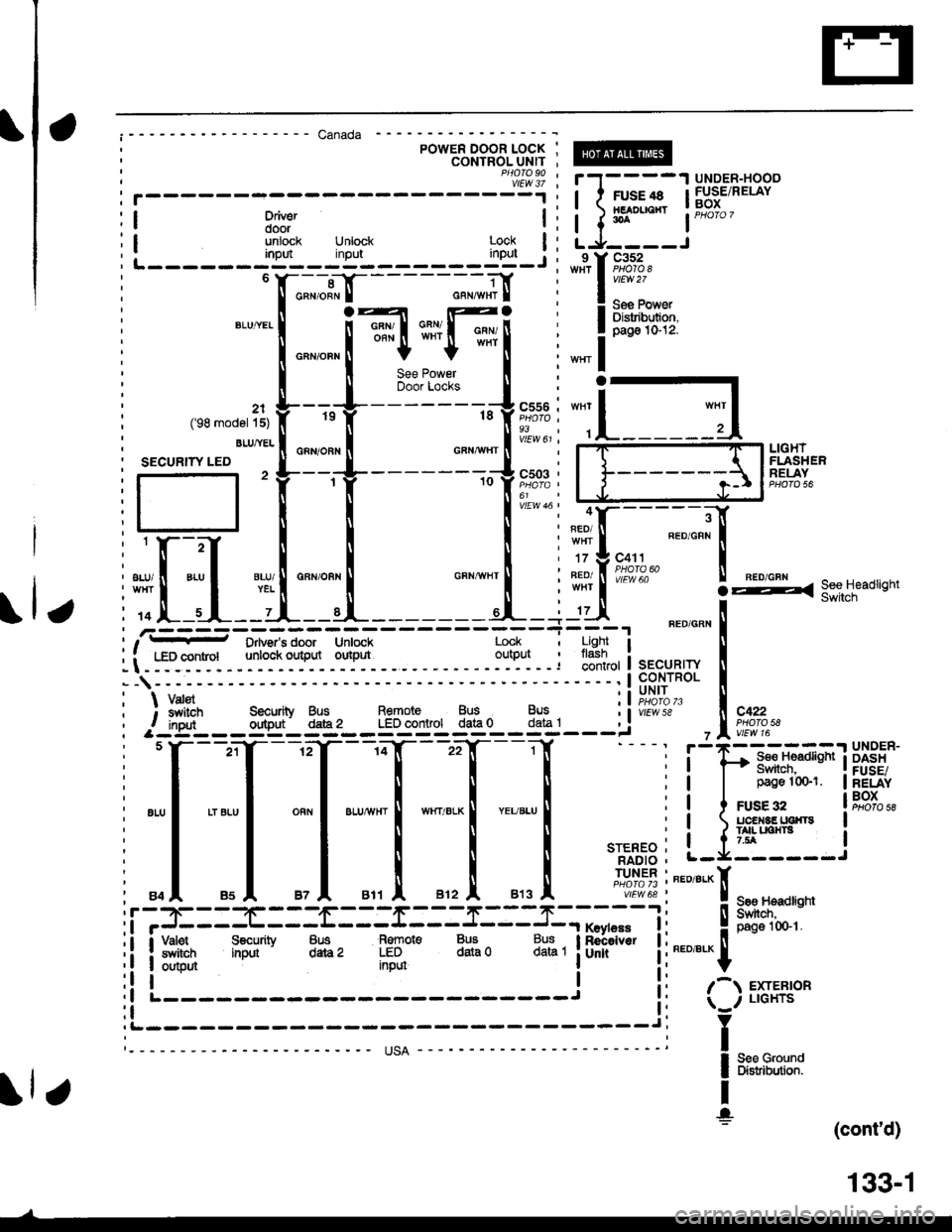
';;;1; I r1-- --'I UNDE'------J-i i I 11'.1'.11 lSBi'"Driver .r ' HEADIIOriT '::
door !:t { t-- lPHo'o7unlock Unlock Lock | : L j,- -- -Jinpd input lpr,_j : -9lT1u.r^ -
---- Canada ---'------l
POWER DOOR LOCK ;CONTROL UNIT ,
k;i
L______jg:_l=,_______ juj_.r, _r_f 9_.-u:'F":;!-_ --",*tI
i !**""""I
*",*"[T*Fi
i
.",1
o*u*u'
,* -".11 t-J--'-----'-hff I
"ll-_-_il
|semooeriir f,
't
tr
18 f ia-eii,
L______d"t";tlo"n,o"n| """*",|ft"t'i fsEcuRrwLED,, L--J---------J",0. | | -liffi*
,i,Hfil _[l!,ffisHdsh
i ,of.--s L--d,---t--------cl-+-'dl "."""" !-------t - I, t - Drivgr's door Unlock Lock I Light I U
ii -F-o-:y-"1 - -:i"-1i3y. -TTi- - - - - :"ll'i - - ; 13'*" i q._"u_n'r !--1---- ---'l99,trRoL I
: \varst :l;#"b" I; ; $vitch Securiiv Bus Remote Bus Bus i I vttwte ll C422, f inqrt outDut d€,.az LED control data 0 data l , : I P1oTo 58-a- --' s Y---^a---.;f --.;Y---^;Y---:Y - - - - r ;-.tr'---
. ; UNIT
i *t Drtusr's door untock Lock i ugnt it - uavgrs ooor untocx LocK I Lrgn'
: LED control unloc* outpul outrut outpul ' flash- ': ' iontrot I sEcuRlw
--1-"' ---' I coNrRoL' 'i uNlri vatst, I VarEr tl PHQ|AT3: ; s,vitch Securiiy Bus Remote Bus Bus t)vtEwte, f inarr ornout d'de2 LED control data 0 data l� :
7-1 e4re4lon
lfil Iffi;*l
[I$'':r*il
: 84 |, 85A 87A 811 |' Bt2 |' 813 |' vtEw68 | ! sae r.teadli
i i'=::t:::ti------r------s------r, -"** i : ! 8yJfu;; I I Vabt S€curity 8us Remot€ Bus Bus I Reieiver ! ; --_ _.._ ll
:i iffi$ input data2 ffiDul
datao datal iunrr !:""'"^l
(cont'd)
133-1
Page 2044 of 2189
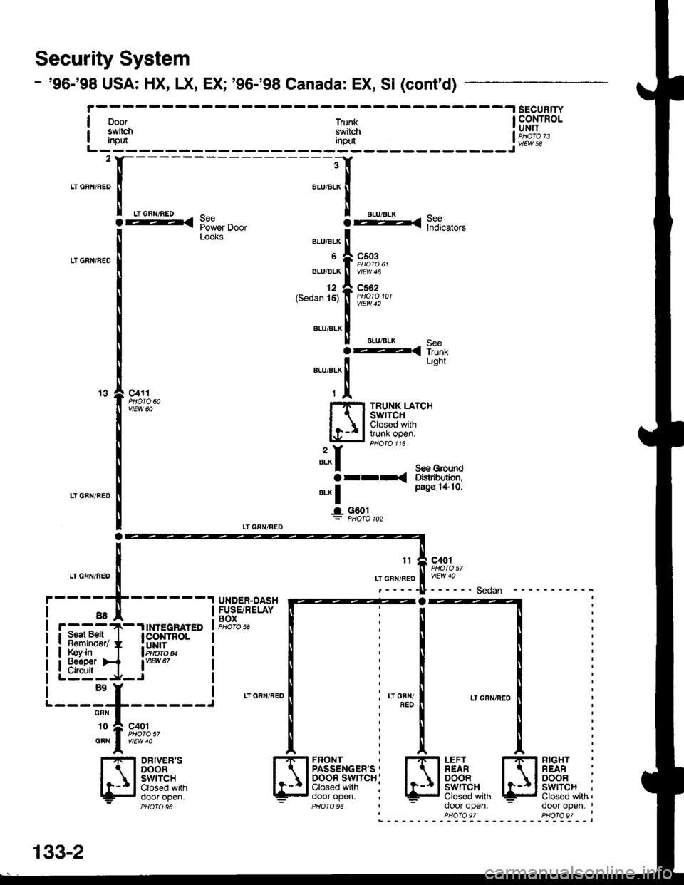
Security System
- '96-'98 USA: HX, LX, EX; '96-'98 Canada: EX, Si (cont'd)
I ooor
| #Iflinput
-----l sEcuRlrY
LT CRN/FED
LT GFN/RED
LT GBN/REO
a
[ "*
LT.FN,BED
i
.l:T,lT_t
i _ _ ;T_-----l Hui.'n*f' ffi i|. :-:?-'IINTEGB]ATED I PHoro 58 ll ,
!E����������������ilf8t+ lffi'il* ! ! :
LE:E,jJ_i*- | I i
c503
c562
vtEvl 42
BLU/BLK EAA-{ i,i-"i
See GroundDislrihJtion,pag€ 1*10.
c401
------Sedan
Inpur
---{ F6,i,",. ooo. i:< "?;",o,"
trllnxswitchI CoNTROL! UNITI PHora 73
JvtEw sB
2
BLU/ALK
6
BLU/ALK
12(Sedan '15)
BLU/BLK
c411PHOIO 60vtEw 60
H
":-f
Or--<
".^ |l- G601
Light
TRUNK LATCHswrTcHClosed withvunK open.
LTGRN/FED
t___:'I______l
Tll """,
l-.'F-l DRtvER.s| 1 I DooR
Ir-Il3)lll8l,*=- ooor open.- PHOfOg6
LTGRN/REO i ; LT GFN/T,FED
*'^l ft?{,,' I iFRONTPASSENGER'S '
DOOR SWICH:Closed with :door open.PHOTO 96HH
LEFTREARDOORSWITCHClosed withdoor open.
rflf5ii' :
lCJEfii:t*,,,'i- .l^^r ^^6^ |
PHOfO 97
133-2
Page 2053 of 2189
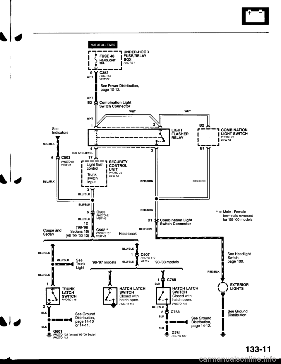
UNDER.HOODl t FUsE4s I FUSEiRELAY! xamucnr ! BoX
I I.A I PHoro 7
LJ,----Jc352
vtEw 27
Soe Pow€r Distdbulion,page 1&12,
Combination LightSwitch ConnectorE2
SeelndicatorsCOMBINATIONI I LIGHT SWITCH
| | v;iw; -
LIGHTFLASHERRELAY
4aLU or ALU/YEI
c503
iTFffiliBi+B,il:"'s#Ji"" I coNrRoL
i#$ iI input IL ----J3YBLU/BLK ll:aBrui 8rK ll
*,rlfr ftT-f.","
,^ftslllfl li^ir,, Ha,chback
vtEw 58
Coupa tndSedan
Combination LightSwitqh Connector
r = l\,lale - Femaletermrnals reversedlor'99-'00 models
See HeadlightSwiich,peg61(n.
EXTERIORLIGHTS
Seo GroundDistribution
"'u'"t*X
".u,"."aE,<
-*;"1
SeeTrunkLight
'9+ 97 models
aau,"a" fi
'*9#1",,,
BLU/BLKrf vEwe g8-,oo modets
l
qi*$qli-
TRUNKLATCHswrTcH
":^f se€ Ground
5--r< !#itl8".* I o"o'
or 14-11
.|- PHOIO ro2lorcoDr'99 oo sedan): PHofo 113
";-f "^'
FE
I-I-t HATCH LATCHI I I swtrcx
lljij::,:}#x""'*if
"tut
seecroundo tr
e.* | Page 14-12'
+ 9131",,,
133-11
Page 2055 of 2189
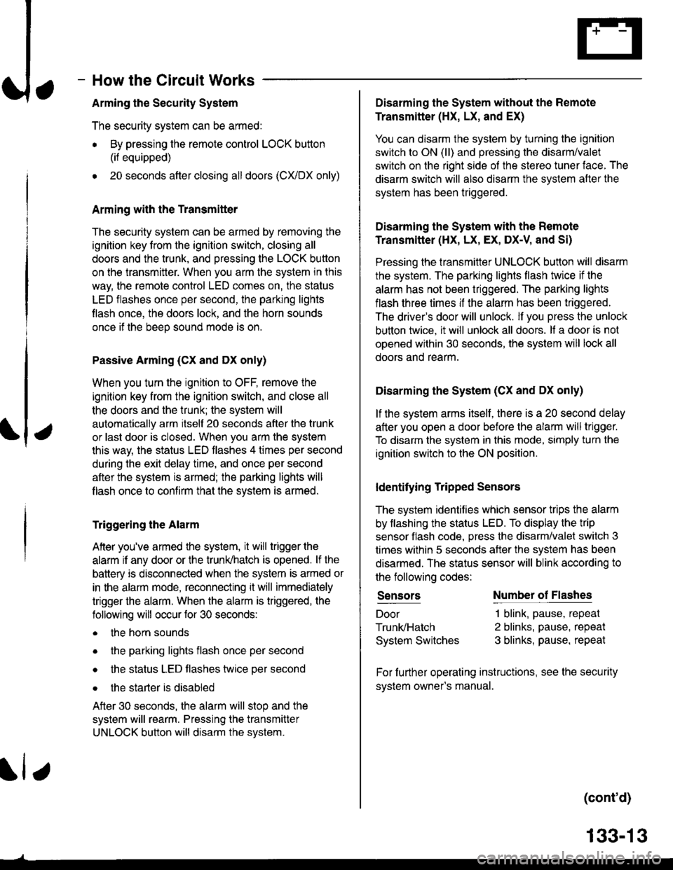
How the Circuit Works
Arming the Security System
The security system can be armed:
r By pressing the remote control LOCK button
(if equipped)
. 20 seconds atter closing all doors (C)UDX only)
Arming with the Transmitter
The security system can be armed by removing the
ignition key from the ignition switch, closing all
doors and the trunk, and pressing the LOCK button
on the transmitter. When you arm the system in this
way, the remote control LED comes on, the status
LED flashes once per second, the parking lights
flash once. the doors lock. and the horn sounds
once if the beeo sound mode is on.
Passive Arming (CX and Dx only)
When you turn the ignition to OFF, remove the
ignition key from the ignition switch, and close all
the doors and the trunk; the system will
automatically arm itself 20 seconds after the trunk
or last door is closed. When you arm the system
this way, the status LED tlashes 4 times per second
during the exit delay time, and once per second
after the system is armed; the parking lights will
flash once to confirm that the system is armed.
Triggering the Alarm
Atter you've armed the system, it will trigger the
alarm if any door or the trunldhatch is opened. lf the
battery is disconnected when the system is armed or
in the alarm mode, reconnecting it will immediately
trigger the alarm. When the alarm is triggered, the
following will occur for 30 seconds:
. the horn sounds
o the parking lights flash once per second
. the status LED flashes hvice oer second
. the starter is disabled
After 30 seconds, the alarm will stop and the
system will rearm. Pressing the transmitter
UNLOCK button will disarm the svstem.
tlr
133-13
Disarming the System without the Remote
Transmitter (HX, LX, and EX)
You can disarm the system by turning the ignition
switch to ON (ll) and pressing the disarm/valet
switch on the right side ol the stereo tuner face. The
disarm switch will also disarm the svstem after the
system has been triggered.
Disarming the System with the Remote
Transmitter (Hx, Lx, Ex, DX-V, and Si)
Pressing the transmitter UNLOCK button will disarm
the system. The parking lights llash t\ivice if the
alarm has not been tnggered. The parking lights
flash three times if the alarm has been triggered.
The driver's door will unlock. lf you press the unlock
button twice, it will unlock all doors. lf a door is not
opened within 30 seconds, the system will lock all
doors and rearm.
Disarming the System (CX and DX only)
lf the system arms itself, there is a 20 second delay
after you open a door before the alarm will trigger.
To disarm the system in this mode, simply turn the
ignition switch to the ON position
ldentitying Tripped Sensors
The system identifies which sensor trips the alarm
by flashing the status LED. To display the trip
sensor flash code, press the disarm/valet switch 3
times within 5 seconds after the system has been
disarmed. The status sensor will blink according to
the followino codes:
SensorsNumber of Flashes
Door
TrunldHatch
System Switches
1 blink, pause, repeat
2 blinks, pause, repeat
3 blinks, pause, repeat
For further operating instructions, see the security
syslem owner's manual.
(cont'd)