Page 1367 of 2189
Seats
Front Seat Disassembly and Reassembly
CAUTION: When prying with a flat-tip screwdriver, wrap it with protective tape to prevent damage.
NOTE: SEAT-BACK. Take care not to scratch the seat covers and body.. Remove the front seat through the door openlng.
Driver's:
SEAT CUSHION
HEADREST
PIVOT NUTI x 1.25 mm22 N.m 12.2 kgf,m,16 tbf.ft)
CENTER COVER
8 x 1.25 mm
LOWER CAP
RECLINE ADJUSTER
WASHER
20 N.m 12.0 kgf.m,lil lbtftl
WASHERS
EUSHING
10 x 1.25 mm47 N.m (4.8 kgf.m,3s rbl.ft)
INNER SEATTRACKRECLINECOVER
WASHER
8 x 1.25 mm20 N.m (2.0 kg,f.m,14 tbf.fit
LOWER CAPI
8 x 1.25 mm20 N.m {2.0 kgI.rn,l4 tbf.ft)
i\",-,"
20-13A
HEIGHT HANDLE
Page 1640 of 2189

Headlights
Adjustment (cont'dl
Turn the low beams on.
Determine if the headlights are aimed properly.
Vsrtical adiustmsnt:
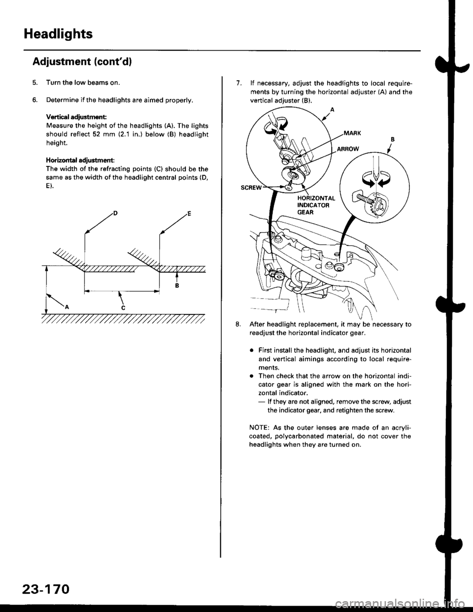
Measure the height of the headlights (A). The lights
should reflect 52 mm \2.1 in.) below (B) headlight
height.
Horizontal adi$tment:
The width of the refracting points (C) should be the
same as the width of the headlight central points (D,
23-170
7. lf necessary, adjust the headlights to local require-
ments by turning the horizontal adjuster (A) and the
vertical adjuster (B).
After headlight replacement, it may be necessary to
readjust the horizontal indicator gear.
. First installthe headlight, and adjust its horizontal
and vertical aimings according to local require-
ments.
. Then check that the arrow on the horizontal indi-
cator gear is aligned with the mark on the hori-
zontal indicator,- lf they are not aligned, remove the screw, adjust
the indicator gear, and retighten the screw.
NOTE: As the outer lenses are made of an acryli-
coated, polycarbonated material, do not cover the
headlights when they are turned on.
Page 1710 of 2189
Gruise Control
Component Location Index
MAIN SWITCHTesVReplacement,page 23-242CABLE REELReplacement, section 24
BRAKE SWITCH, fest, page 23-244. Pedal Height Adjustment,section 19CRUISE CONTROI. UNITInput Test, page 23-240
swrTcH {M/T). Test. page 23-244. Clutch Pedal Adjustment,section 12
atfSWTTCH. Test, page 23-154' Replac€ment, page 23-'155
ACTUATOR CABLEAdjustment, page 23-246
VACUUM TANK
TOR ASSEMBLY. Test, pag€ 23-245. Replacement, page 23-246. Solenoid Test, page 23-247' Disassembly, page 23-248
23-240
Page 1716 of 2189
Cruise Control
Brake Switch Test
1. Disconnect the 4P connector from the switch.
4P CONNECTOR
BRAKEPEDAL
Check for continuity between the terminals accord-
ing to the table.
Terminal
t"r. ** \
123
RELEASEDo---o
DEPRESSEDoo
3. lf necessary. replace the switch or adjust pedal
height (see sectionl9).
23-246
clutch switch Test (M/Tl
1. Disconnect the 2P connector from the switch.
swtTcH
2. Check for continuity between the terminals accord-
ing to the table.
Terminal
.***aal
-\I2
RELEASED
DEPRESSEDo--o
3. lf necessary, replace the switch or adiust pedal
height (see section '12).