Page 1175 of 2189

Master Cylinder/Brake Booster
IRemovaUlnstallation
CAUTION:
. Be care{ul nol to bend or damage the brake lines when
rsmoving the mastsr cYlinder.
. Do not soill brakefluid on the vehicle; it may damage
the paint; if brake fluid does contact the paint, wssh
it off immediatelY with water'
. To prevent spill3, cover the hose ioints with rags or
shop towels.
9. Remove the four booster mountlng nuts
10. Pull the brake booster forward until the clevis is
clear of the bulkhead.
11. Remove the brake booster from the engine com-
panmenr.'12. Install the brake booster and master cylinder in the
reverse order of removal.
CAUTION:
. When connecting the brake lines. make sure
that there is no inte erence between the brake
lines and oth6r Parts.
r Be careful not to bend or damage the brake lines
when installing the master cylinder.
NOTE: lf replacing the master cylinder or brake
booster, check and adiust the pushrod clearance
be{ore installing the master cylinder (see page 19-221'
Fill the master cylinder reservoir, and bleed the
brake svstem (see Page 19-7).
After installation. check the brake pedal height and
brake pedal tree play (see page l9-5) and adjust if
necessary.
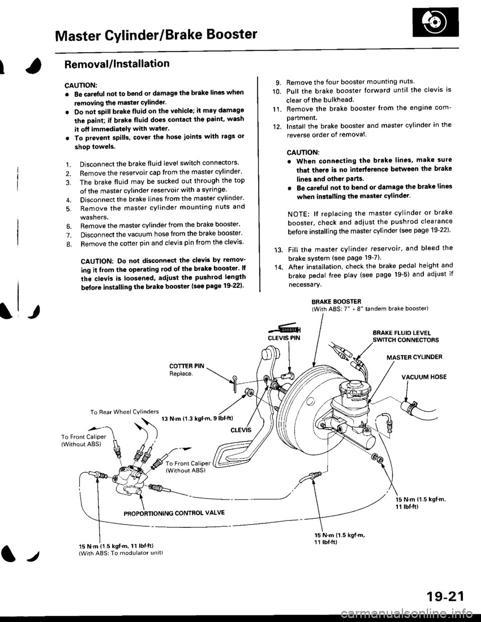
BRAKE BOOSTER(With ABS: 7" + 8" tandem brake booster)
BRAKE FLUIO LEVELSWITCH CONNECTORS
MASTER CYLINDER
VACUUM HOSE
1.
2.
3,
5.
Disconnect the brake fluid level switch connectors'
Remove the reservoir cap from the master cylinder'
The brake fluid may be sucked out through the top
of the master cylinder reservoir with a syrlnge.
Disconnect the brake lines from the master cylinder'
Remove the master cylinder mounting nuts and
washers.
\l/
6. Remove the master cylinder from the brake booster'
7. Disconnect the vacuum hose trom the brake booster'
8. Remove the cotter pin and clevis pin from the clevis'
CAUTION: Do not disconnect the clevb by remov-
ing it from the operating rod of the brako booster' lf
the clevis is loosened, adiust the pushrod length
before installing th€ brake booster (see page 19-221'
COTTER PINReplace.
To Rear Wheel Cylinders
14.
-6.4CLEVIS PIN
To Front Caliper(Without ABS)$
t'N't'ttrnt'-''
To Front CaliperlWithout ABSi
PBOPORTIONING CONTROL VALVE
15 N.m {1.5 kgl m,11 tbtft)
15 N.m {1.5 kgif.m, 11 lbtft}(With ABS: To modulator unit)lr
19-21
Page 1177 of 2189

Brake Booster InsPection
FunctionalTest
1. With the engine stopped, depress the brake pedal
several times to deplete the vacuum reservoir, then
depress the pedal hard and hold it for 15 seconds lf
the pedal sinks' either the master cYlinder is
bypassing internally, or the brake system (master
cylinder. lines. modulator, proportioning control
valve, or caliPer) is ieaking.
2. Start the engine with the pedal depressed lf the
pedal sinks slightly, the vacuum booster is operating
normally. lf the pedal height does not vary, the
booster or check valve is faultY.
3. With the engine running. depress the brake pedal
lightly. Apply just enough pressure to hold back
automatic transmission creep. lf the brake pedal
sinks more than 25 mm (1.0 in.) in three minutes,
the master cvlinder is faulty. A slight change in
pedal height when the A'lC compressor cycles on
and off if normal. (The A/C compressor load
changes the vacuum available to the booster')
Leak Test
1. Depress the brake pedal with the engine running.
then stop the engine. lf the pedal height does not
vary while depressed for 30 seconds, the vacuum
booster is OK. lf the pedal rises. the booster is
faulty.
2, With the engine stopped, depress the brake pedal
several times using normal pressure When the
Dedal is first depressed, it should be low On con-
secutive applications, the pedal height should grad-
uallv rise. lf the pedal position does not vary, checK
the booster check valve.
l./
19-23
Booster Check Valve Test
1. Disconnect the brake booster vacuum hose at the
booster.
2. Stan the engine and let it idle. There should be vac-
uum. lf no vacuum is available, the check valve is
not working properly. Replace the brake booster
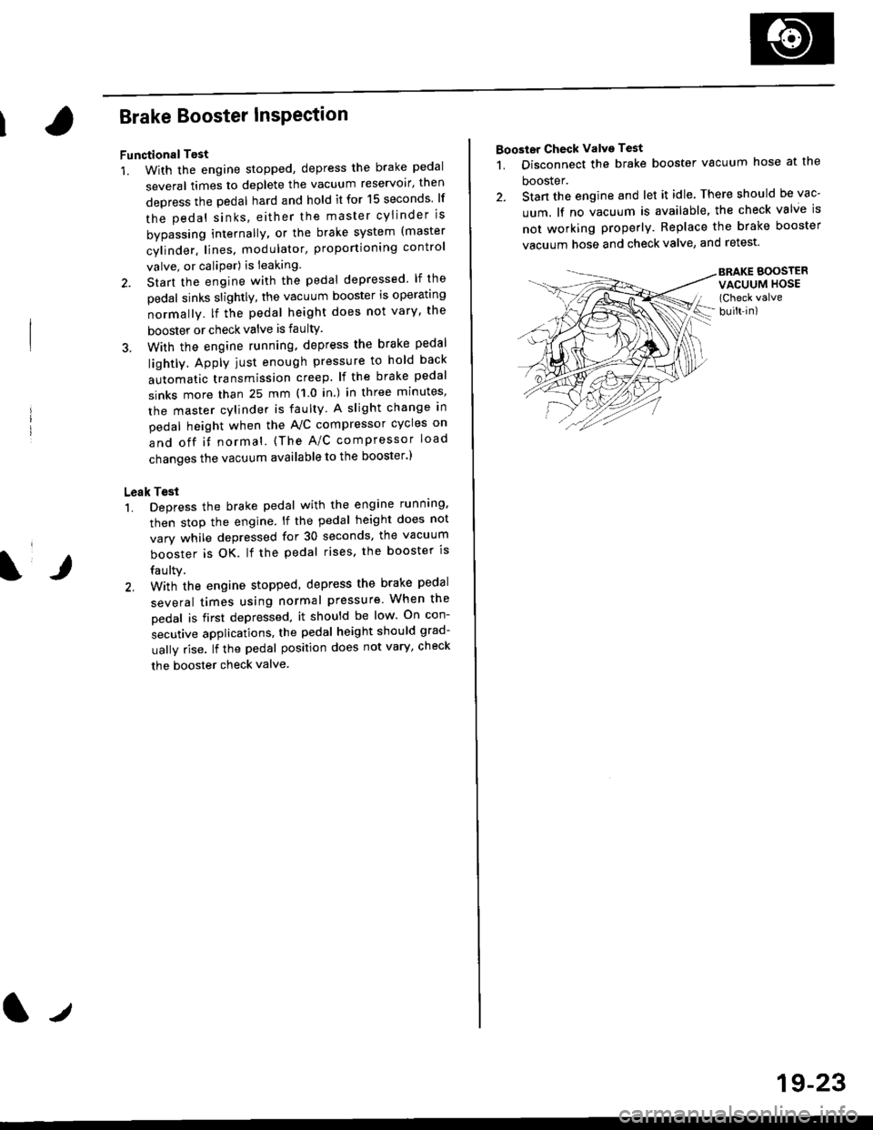
vacuum hose and check valve, and retest.
BRAKE BOOSTERVACUUM HOSE(Check valve
built-in)
Page 1281 of 2189

Troubleshooting
SymptomProbable Cause
Water leaks1. Clogged drain tube.
2. Gap between glass weatherstrjp and roof panel.
3. Defective or improperly installed glass weatherstrip.
4. Gap between drain seal and roof panel.
Wind noise'1. Excessive clearance between glass weatherstrip and roof panel.
Motor noise1. Loose motor.
2. Worn gear or bearing.
3. Cable assembly deformed.
Glass does not move, but motor turns'1. Clutch out of adjustment.
2. Foreign matter stuck between guide rail and slider.
3. lnner cable loose.
4. Cable assembly not attached properly.
Glass does not move and motor does not turn
{glass can be moved with moonroof wrench)
1. Blown fuse,
2. Faulty switch.
3. Battery run down.
4. Defective motor.
5. Faulty relay.
D
Glass Height Adjustment
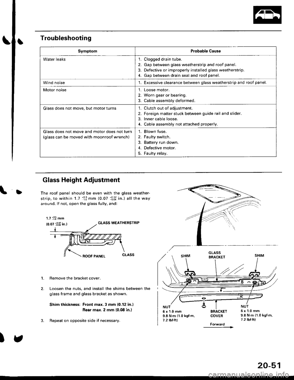
The roof panel should be even with the glass weather-
strip, to within 1.7 :lr3 mm (0.07 :3:31 in.) all the way
around. lf not, open the giass fully, and:
GLASS WEATHERSTRIP
1. Remove the bracket cover.
Loosen the nuts, and install the shims between the
glass frame and glass bracket as shown.
Shim thickness: Front max.3 mm 10,12 in.l
Rear max. 2 mm 10.08 in.)
Repeat on opposite side i{ necessary.
)
5x1.0mm9.8 N.m 11.0 kgf m,7.2 rbtft)
SRACKETCOVEB
----------1>
6x1.0mm9.8 N.m {1.0 kgtm,7.2 tbf.ft)
1.7 tl.8 mm
{0.07 :3 3i in.}
20-51
Page 1283 of 2189
b
D
9. Remove the rail holder A.
GLASS BRACKET
DRAIN CHANNEL ROO STOPRotate as shown to remove it from the guide rail.
10. Remove the drain channel rod slider by moving the
cable slider forward using the moonroof wrench.
'11. Detach the drain channel rod stop from the cutout
of the guide rail as shown.
DRAIN CHANNELROD
I
NUT6x1.0mmI N.m (0.9 kgf.m,SUNSHAOE
\
'14.
12. Slide the sunshade forward, then remove it.
Installation is the reverse of the removal procedure.
NOTE: Check the glass height (see page 20-51).
Check for water leaks,
NOTE: Do not use high-pressure water.
20-53
Page 1286 of 2189
Moonroof
1.
2.
Switch Plate Adjustment (Fully Closed Positionl
3.
4.
5.
Remove the headliner {see page 20-64).
Using the moonroof wrench, close the glass fully.
NOTE: Check the glass fit to the rool panel.
Using an open-end wrench, loosen the switch plate mounting bolts.
Adjust position of the switch plate (switch cam) as shown.
Check the operation of the glass (from tilt-up position to fully closed position, from the fully open position to the fully
closed position) by operating the moonroof switch.
NOTE: Check the glass height (see page 20-51).SWITCH PLATE
GUIDEPLATE
SWITCH CAM
While moving the switch plateplate at the position where thea (a faint click is heard).
INNER CABLE END
little bv little, secure the switchswitch cam contacts the switch
Close the glass fully, and check for water leaks.
NOTE: Do not use high-pressure water.
CAELE BRACKET
20-56
Page 1287 of 2189

Opening Drag Check
{Motor Removed)
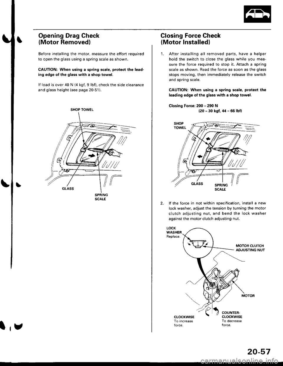
Before installing the motor, measure lhe effort required
to open the glass using a spring scale as shown.
CAUTION: When using a spring scale, pfotest the lead-
ing edge ol the glass with a shop towel.
lf load is over 40 N (4 kgf,9 lbf), check the side clearance
and glass height (see page 20-51).
SHOP TOWEL
l,e
20-57
Closing Force Check
(Motor Installedl
'1. After installing all removed parts, have a helper
hold the switch to close the glass while you mea-
sure the force required to stop it. Attach a spring
scale as shown. Read the force as soon as the glass
stops moving, then immediately release the switch
and spring scale.
CAUTION: When using a spring scale, protect the
lerding edge ol the glass with a shop towel.
Closing Force: 200 - 290 N(20 - 30 kst, 44 - 66 lbfl
lf the torce in not within specification, install a new
lock washer, adjust the tension by turnang the motor
clutch adjusting nut, and bend the lock washer
against the motor clutch adjusting nut.
LOCKWASHERReplace.
COUNTER.cLocKwrsETo decrease
SCALE
Page 1326 of 2189
Hood
Adjustment
NOTE: Before adjusting the hood, loosen each bolt slightly.
1. Adjust the hood hinges right and left, as well as fore and aft, by using the elongated holes.
2. Turn the hood edge cushions, as necessary. to make the hood fit flush with the body at front and side edges.
3, Adjust the hood latch to obtain the proper height at the forward edge.
4. After adjustment, tighten each bolt securely.
6x1.0mm9.8 N.m {1.0 kgt.m,7.2 tbt.tll
NOTE: Move the hood latch right or left
is centered in the hood latch as shown.
)
until the striker
6x1.0mm9.8 N.m {1.0 kgf.m,7.2 tbf.ftl
\
20-96
Page 1364 of 2189
Body ('99 model)
Dashboard
Center Panel Removal and
lnstallation
Bumpers
Front Grille Removal and
lnstallation
Front Air Spoiler Replacement ."'.....
Seats
Front Seat DisassemblY and
ReassemblY 20-138
Front Seat Torsion Bar
Replacement '.'...".'....'... 20-139
Emblems
tnstallation 20-140
20-136
20-136
20-137
Outline of '99 Model Changes
The center Danel removal and installation procedures are different'
The front grille removal and installation procedures are different'
The front air spoiler has been added for some models of 2D'
A height-adjustable driver's seat was added to some models'
Emblems were added for some models ot 2D'