Page 1802 of 2189
Troubleshooting
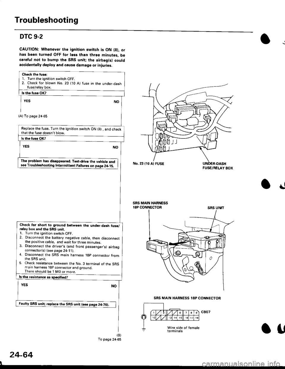
DTC 9-2
CAUTION: Whenever the ignition switch is ON 0l), ofhas been turned OFF lor lass than three minutes, becareful not to bump the SRS unit; the airbag(s) couldaccidentally deploy lnd caqse damage or iniuries.
Check the tu.c:1. Turn the ignition switch OFF.2. Check for blown No. 23 (10 A) fuse in the under,dashfuse/relay box.
Replace the tuse. Turn the ignition switch ON lll) , and checkthat the fuse doesn't blow.
Th6 problem hs3 disappe.rod, TGt-dJiv€ the vehiclo and3ee Troublerhooting Intermiftcnt Failuro3 on paqo 2l-15.
Check tol short to ground betwe.n tho unde.-da3h fus./r.ley box and the SRS unit.1. Turn the ignition switch OFF.2. Disconnect the baftery negative cable, then disconnectthe positive cable, and waittorthree minutes.3. Disconnect the driver's (and front passenger,s) airbagconnector(s) (see page 24-11).4. Disconnect the SRS main harness 1gp connector fromthe sRs unit.5. Check resistance between the No. 3 terminal of the SRSmarn harness 18P connector and ground,There should be 1 MO or more.
Feufty SRS unh; rcphce the SRS unit lsee pag.2+761.
(A)To page 24-65
To page 24-65
No. 23 lr0 Al FUSEFUSE/RELAY BOX
!
SRS MAIN HARNESS18P CONNECTORSRS UN'T
24-64
I
SRS MAIN HARNESS 18P CONNECTOR
Otf
Page 1803 of 2189
)
FUSE/BELAY BOX
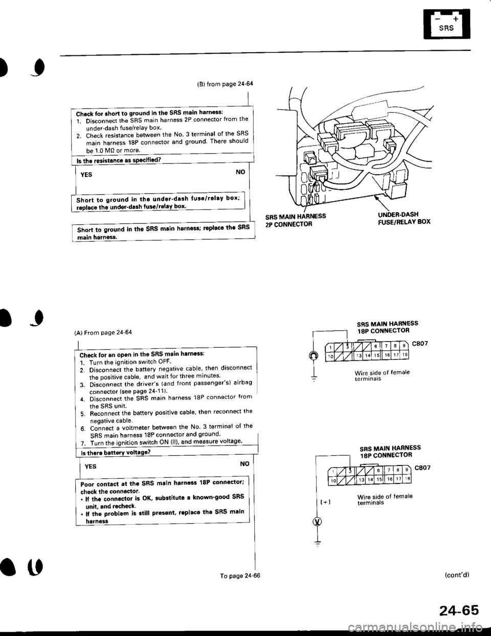
Chcck for an op€n in th6 SRS main harness:
1. Turn the ignition switch OFF.
2. Disconne;t the battery negative cable, then disconnect
the positive cable, and wait for three minutes'
3. Disconnect tho driver's (and front passenger's) airbag
connector (see Page 24'11).
4. Disconnect the SRS main harness 18P connector from
the SRS unit
5. Reconnect the battery positive cable, then reconnect the
neoative cable.
6. Co-nnect a voltmeter betlveen the No 3 terminal ol the
SFS main harness 18P connector and ground'
7. Turn theswitch ON (ll), and m€asure
(cont'd)
(B) from page 24-64
Check tor ahort to ground in the SRS main harn$s:
1. Disconnect the SRS main harness 2P connector from the
under-dash fuse/relaY box.
2. Check resistance between the No. 3 terminal of the SRS
main harness 18P connector and ground There should
be 1.0 M0 or more.
ls the re3istance a3 specified? -
NOYES
Short to giound in tho undot-drlh lut'/rol'y box;
replace the undel-da3h fusgtgEl!9l--------.-
Short to ground in tho SRS m.in harn$s; ropleco the SRS
main harness.
(AlFrom page 24'64
Poor contact at the SRS main harnoss 18P connoctor;
check lho connoctor.. ll the connector k OK, sub3titute r known'good SRS
unh. and recheck. lf the problom is slill present, lepl.ce the SRS main
To page 24-66
SRS MAIN HARNESS18P CONNECTOR
o0
24-65
Page 1807 of 2189
)
5, Reconnect the airbag connector(s)'
Front Passengor's Side:
a Attach the airbag connector to the connector holder'
then reinstallthe glove box.
FRONT PASSENGER'S AIRBAG
oo
24-69
Driver's Side:
a Connect the driver's airbag 2P connector to the cable
reel 2P connector, then install the acc€ss panel on the
steering wheel
DRIVER'S AIRBAG2P CONNECTOR
6. Connect the battery positive cable, then connect the
negative cable.
7. After installing the
operatlon:
. Turn the ignition
tor light should
and then go off
a Make sure both horn buttons work
airbag, confirm Proper sYstem
switch ON (ll); the SRS indica-
come on for about six seconds
Page 1808 of 2189
Airbag
Disposal
Before scrapping any airbags (including those in a wholevehicle to be scrapped), the airbags must be deployed. lfthe vehicle is still within the warranty period, before youdeploy the airbags, the Honda District Service Managermust give approval and/or special instructions. Onlv afterthe airbags have been deployed (as the result of vehiclecollision, for example), can they be scrapped.lf the airbags appear intact (not deployed). treat themwith extreme caution.
Follow this p.ocedure:
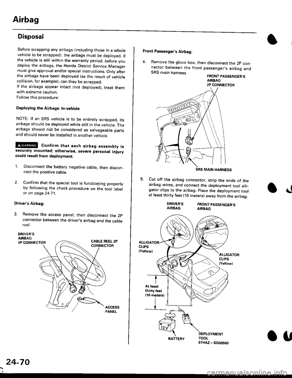
Deploying the Airbags: In.vehiclo
NOTE: lf an SRS vehicle is to be entirely scrapped, itsairbags should be deployed while still in the vehicle. Theairbags should not be considered as salvageable partsand should never be installed in another veh;cle.
!@ confirm thst oach airbag assembty issecurely mounted; otharwiso. sev€re personal iniurycould result lrom deployment.
1. Disconnect the baftery negative cable, then discon_nect the positive cable.
2. Confirm that the special tool is functioning properlyby following the check procedure on the tool labelor on page 24-'l'l .
Driver's Airbag:
3. Remove the access panel, then disconnect the 2pconnector between the driver,s airbag and the cablereet.
DRIVER'SAIRBAG2P CONNECTOR
24-70
BATTERY.U
Front Passenger's Airbag:
4. Remove the glove box, then disconnect the 2p con-nector between the lront passenger,s airbag andSRS main harness.FRONT PASSENGER'SAIREAG2P CONNECTOB
SRS MAIN HARNESS
Cut off the airbag connector, strip the ends of theairbag wires, and connect the deployment tool alli_gator clips to the airbag. place the deployment toolat least thirty feet (10 meters) away from the airbag.
a!
DRIVER'SAIRBAGFRONT PASSENGER'SAIRBAG
ALLIGACLIPS(Yellow)ALLIGATORCLIPS{Yellowl
At loastthiny toet(10 metorsl
Page 1813 of 2189
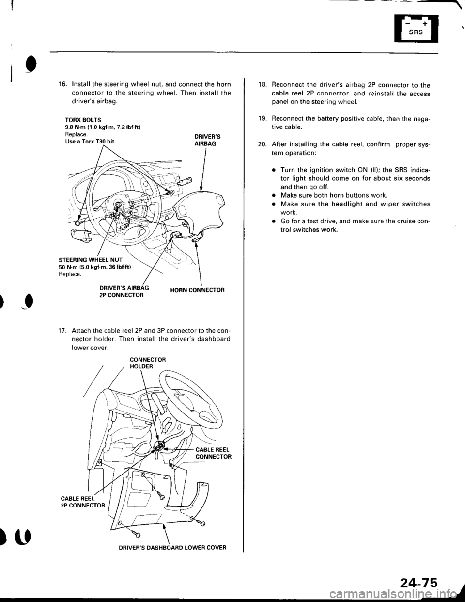
16. Install the steering wheel nut, and connect the horn
connector to the steering wheel. Then install the
driver's airbag.
TORX SOLTS9.8 N m 11.0 kgf m, 7.2 lbtftlReplace.Use a Torx T30 bit.
STEERING WHEEL NUT50 N.m 15.0 kgf.m,36lblft)Replace.
DRIVEB'SAIRBAG
DRIVER'S2P CONNECTOBHORN CONNECTOB
I
17.Attach the cable reel 2P and 3P connector to the con-
nector holder. Then install the driver's dashboard
lower cover.
)UDRIVER'S DASHBOARD LOWER COVER
24-75
18. Reconnect the driver's airbag 2P connector to the
cable reel 2P connector. and reinstall the accesspanel on the steering wheel.
19. Reconnect the battery positive cable, then the nega-
tive cable.
20. After installing the cable reel, confirm proper sys-
tem operation:
Turn the ignition switch ON (ll); the SRS indica-
tor light should come on for about six seconds
and then go off.
Make sure both horn buttons work.
Make sure the headlight and wiper switches
Go for a test drive, and make sure the cruise con
trol switches work.
a
a
Page 1946 of 2189
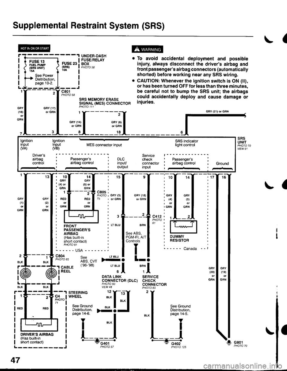
Supplemental Restraint System (SRS)
(
FUSE 13FUELPUUPFBA UMT)15A
See PowerDistibution,page 10-2.
FUSE 23(sRs)
c801PHOTO 58
SRS MEMORY ERASESTGNAL (MES) CONNECTORPHO|O 111
. To avoid accidental deployment and possible
iniury always disconnect the driver's airbag and
f ront passenger's airbag connectors (automatically
shorted) before working near any SRS wiring.
. CAUTION: Whenever the ignition switch is ON (tt),
or has been turned OFF for less than three minutes,
be caretul not to bump the SRS unit; the airbags
could accidentally deploy and cause damage or
iniuries.
UNDER-DASHFUSE/RELAYBOX
GFY 07)or GFN{18)
GFN
GFYt2l
GFN
GRY0)
GFN
2
ALK
J (ii
t\
GFY O4)or GRN
SRSUNIT
a
-ffiffi,*l-{
H!=";=_J
iffii'r:fi:*" i tH-
PHOIO 125short contact) | - FCqOtL_________J PHO|A 57
47
GAY (21) or GRN
lgnitionInput(VA)
Driver's
cont.ol
lgnitioninput(VB)MES connector inputSRS indicatorlighl control
Service t------check : Passengefs ;connector ; airbag control , GroundInpu , /+rr I pir-r
Passenger'sai|bag conlrol; prc..t rnpuv, Ourpul
14GRY(5) orGFN
rffi{{_ilil
i ffi i""'"1*"o,"'.1'' i lffil
ffirtu!-T:l
ir:r*::"."
ilstEl'{s6.e8'�
'"'Jl "Tl
, I oATA L|NK SERVTCE: CoNNECTOR (DLC) CHECK,J piarasa CONNECTORvtEw48