2000 HONDA CIVIC Speed sensor
[x] Cancel search: Speed sensorPage 370 of 2189

DTC(MlL indicationlDetection ltemProbable CausePage
P1336(54iCrankshaft SpeedFluctuation SensorIntermittent Interruption
. CKF sensor11 183
P1337 (54)Crankshaft SpeedFluctuation SensorNo Signal
CKF sensorCKF sensor circuitECM,PCM
11-'183
P13s9 (8)Crankshaft Position/TopDead Center SensorDisconnected
' CKP/TDC sensor circuit11-187
P1361 (8)Top Dead CenterSensor IntermittentInterruptron
. tuL sensor
11-172
P1362 (8)Top Dead CenterSensor No SignalTDC sensorTDC sensor circuitECIV/PCM
11-172
P1381 {9)Cylinder Position SensorIntermittent Interruption
. CYP sensor11-172
P1382 (9)Cylinder Position SensorNo SignalCYP sensorCYP sensor circuitECM/PCM
11-112
P1456*5(90)
Evaporative Emission ControlSystem Leak Detected {FuelTankArea)
FuelfillcapVacuum connectionFu€ltankFuel tank pressure sensorEVAP bypass solenoid valveEVAP two way valveEVAP control canister vent shut valveEVAP control canisterEVAP purge control solenoid valve
11-283
P1457*6 (90)
Evaporative Emission ControlSystem Leak Detected (EVAP
Control Canister Area)
Vacuum connectionEVAP control canisterFuel tank pressure sensorEVAP bypass solenoid valveEVAP two way valveEVAP control canister vent shut valveFuel TankEVAP purge control solenoid valve
11-283
L
*6: '96 D16Y8 engine (coupe),'97 Dl6Y7 engine (coupe: KL model, sedan: KL (LXl model),'97 D16Y8 engine (coupe: all models,
sedan: KL model),'98-all models,'99-all models,'00-all models.
(cont'd)
1 1-1 01
I ta
Page 373 of 2189

PGM-FI System
System Description
CKP/TDC/CYP Sensor
MAP Sensor
IAT SensorTP SensorEGR Valve Lift Sensor*'Primary H02SSecondary HO2SVSSBARO SensorELD*'KS€Starter SignalALT FR SignalAir Conditioning SignalA/T Gear Position SignalBattery Voltage {lGN.1}Erake Switch SignalPSP Switch SignalFuel Tank Pressure Sensor*iVTEC Pressure Switch*5Clutch Switch Signal*6Countershaft Speed SensornBMainshaft Speed Sensorrs
-\
----t /
F;ilrr j"-----fi-tri-'r.;l
Fb"t."'i" d" c;;il
F,h"'c;;tr*".io";-l
@."r.l"sc;;ll
EaM/PcM B""k-p F"""till
r\
-:/
Fuel IniectorsPGM-Fl Main Belay {Fuel Pump)MILIAC Valve!y'C Compressor Clutch RelayRadiator Fan Relay*,Condenser Fan RelayALT*'lcMEVAP Purge Control Solenoid
Primary HO2S HeaterSecondary H02S HeaterEGR Control Solenoid Valve*rEGR valve*6EVAP Bypass Solenoid Valve*'EVAP Control Canister Vent Shut
VTEC Solenoid Valve*5DLCLock-up Control Solenoid Valve*aShift Control Solenoid Valve*3Linear Solenoid Valve*3
*1: Dl6Y5 engine*2: USA model*3: CW (D16Y5 ensine), D16Y8 engine and 81642 ensine*4: '96 D16Y8 engine lcoupe),'97 Dl6Y7 engine (coupe: KL model, sedan: KL (LX) model),'97 D16Y8 engine {coupe: all models, sedan: KLmodel),'98-all models,'99'all models,'00-all models+5: D16Y5, D16Y8,816A2 engine*6: M/T (D16Y5 enginei*7: CVT 1D'l6Y5 engine)+8: A/T (D16Y7, D16Y8 engine)*9: '96 D16Y5 engine,'96 D16Y7 engine,'96 Dl6Y8 engine (sedan),'97 D16Y5 engine,'97 Dl6Y7 engine (coupe: KA, KC models, sedan:KA, KC, KL (LX) models, hatchback: all models),'97 D16Y8 engine (sedan: KA, KC modelsi
PGM-FI Sy3lem
The PGM-Fl system on this model is a sequential multipon fuel injection system.
Fuel iniector Timing and Duration
The ECM/PCM contains memories for the basic discharge durations at various engine speeds and manifold air flow rates.
The basic discharge duration, after being read out from the memory. is further modified by signals sent from various sen-
sors to obtain the final discharge duration.
ldle Air Control
ldle Air Control Valve llAC Valve)
When the engine is cold. the A,/C compressor is on, the transmission is in gear, the brake pedal is depressed, the P/S load
is high, or the alternator is charging, the ECM/PCM controls current to the IAC Valve to maintain the correct idle speed.
lgnition Timing Control
. The ECM/PCM contains memories for basic ignition timing at various engine speeds and manifold air flow rates.
lgnition timing is also adjusted for engine coolant temperature.
. Aknockcontrol system was adopted which sets the ideal ignition timing for the octane rating ofthegasoline used.*3
Othgr Control Funqtions
1. Starting Control
When the engine is started, the ECM/PCM provides a rich mixture by increasing fuel injector duration.
2. Fuel Pump Control
. When the ignition switch is initially turned on, the ECM/PCM supplies ground to the PGM-Fl main relay that sup-plies current to the fuel pump for two seconds to pressurize the fuel system.. When the engine is running, the ECI\4PCM supplies ground to the PGM-FI majn relay that supplies current to the fuel
oumo.
. When the engine is not running and the ignition is on, the ECM/PCM cuts ground to the PGM-FI main relay which
cuts current to the fuel pump.
11-104
INPUTS
ENGINE CONTROL MODULE (ECMY
POWERTRAIN CONTROL MODULE (PCM) OUTPUTS
Page 374 of 2189

3.
5.
6.
1.
Fuel Cut-off Control
. During deceleration with the throttle valve closed, current to the fuel injectors is cut off to improve fuel economy at
speeds over the following rpm:. D16Y5 engine (M/T):850 rpm. D]6Y5 engine (CVT), D'16Y8 engine (USA M/T): 920 rpm
. Dl6Y8 engine (USA A,/I), D16Y7 engine (USA A,/T);910 rpm
. D16Y8 engine (Canada M/T), D16Y7 engine (canada): 990 rpm
' D16Y8 engine (Canada M/T): 1,000 rpm
. 816A2 engine: 970 rpm
. Fuel cut-off action also takes place when engine speed exceeds 6,900 rpm (D16Y5, D16Y7 engine; D'16Y8 engine:
7,000 rpm. 816A2 engine: 8.100 rpm), regardless of the position of the throttle valve, to protect the engine from
over-rewing. With '99 Dl6Y7 engine (A,/T) and '99 D16Y8 engine (A./T), the PCM cuts the fuel at engine speeds over
5,000 rpm when the vehicle is not moving.
IVC Compressor Clutch Relay
When the ECM/PCM receives a demand for cooling from the air conditioning system, it delays the compressor from
being energized, and enriches the mixture to assure smooth transition to the A,/C mode
Evaporative Emission (EVAP) Purge Control Solenoid Valve*'
When the engine coolant temperature is above 154'F (68'C). the ECM/PCM controls the EVAP purge control solenoid
valve which controls vacuum to the EVAP purge control canister.
Evaporative Emission (EVAP) Purge Control Solenoid Valve*a
When the engine coolant temperature above 154"F (68"C), intake air temperature above 32"F (0'C) and vehicle speed
above 0 mile (0 km/h) or [Ay'C compressor clutch on and intake air temperature above 160"F (41'C)], the ECM/PCM
controls the EVAP purge control solenoid valve which controls vacuum to the EVAP purge control canister.
Exhaust Gas Recirculation (EGR) Control Solenoid Valve*?
When EGR is required for control of oxides of nitrogen (NOx) emissions. the ECM controls the EGR control solenoid
valve which supplies regulated vacuum to the EGR valve
Alternator Control
The system controls the voltage generated at the alternator in accordance with the electrical load and driving mode,
which reduces the engine load to improve the fuel economy.
ECM/PCM Fail-safe/Back-up Functions
1. Fail safe Function
When an abnormality occurs in a signal from a sensor, the ECM/PCM ignores that signal and assumes a pre-pro-
grammed value for that sensor that allows the engine to continue to run.
2. Back-uD Function
When an abnormality occurs in the ECM/PCM itself, the fuel injectors are controlled by a back-up circuit independent
of the system in order to permit minimal driving.
3. Self diagnosis Function lMalfunction Indicator Lamp (MlL)l
When an abnormality occurs in a signal from a sensor, the ECM/PCM supplies ground for the lvllL and stores the DTC
in erasable memory. When the ignition is initially turned on, the ECM/PCM supplies ground for the MIL for two sec-
onds to check the MIL bulb condition.
4. Two Trip Detection Method
To prevent false indications, the Two Trip Detection Method is used for the HO2S, fuel metering-related. idle control
system, ECT sensor, EGR system and EVAP control system self-diagnostic functions. When an abnormality occurs,
the ECM/PCM stores it in its memory. When the same abnormality recurs after the ignition switch is turned OFF and
ON 0l) again, the ECM/PCM informs the driver by lighting the MlL. However, to ease troubleshooting, this function is
cancelled when you jump the service check connector. The MIL will then blink immediately when an abnormality
occurs,
5. Two (or Three) Driving Cycle Detection Method
A "Driving Cycle" consists ot starting the engine. beginning closed loop operation, and stopping the engine. lf misfir-
ing that increases emissions is detected during two consecutive driving cycles, or TWC deterioration is detected dur-
ing three consecutive driving cycles, the ECM/PCM turns the MIL on. However, to ease troubleshooting, this function
is cancelled when you jump the service check connector. The MIL will then blink immediately when an abnormality
occurs.
(cont'd)
1 1-1 05
.1.
Page 375 of 2189

PGM-FI System
System Description (cont'dl
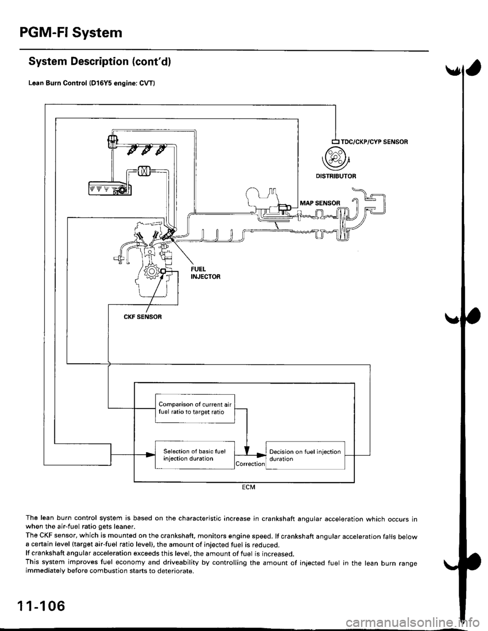
Lean Burn Control {D16Y5 engine: CvT)
The lean burn control system is based on the characteristic increase in crankshaft angular acceleration which occurs inwhen the air-fuel ratio gets leaner.
The CKF sensor, which is mounted on the crankshaft, monitors sngine speed, lf crankshaft angular acceleration falls belowa certain level (target air-fuel ratio level), the amount of injected fuel is reouceo.
lf crankshaft angular acceleration exceeds this level. the amount of fuel is increased.
This system improves fuel economy and driveability by controlling the amount of injected fuel in the lean burn rangeimmediatelv before combustion starts to deteriorate.
1 1-1 06
TOC/CKP/CYP SENSOR
MAP SENSOR
CKF SENSOR
ECM
Comparison oI current airfuel ratio to target ratio
Page 384 of 2189

Manifold Absolute Pressure (MAP) Sensor ('96 Models)
The scan tool indicates Diagnostic Trouble Code (DTC) P0106: A mechanical problem (vacuum leak) in the
Manifold Absolute Pressure (MAP) Sensor system'
TheMAPsensorconvertsmanifoIdabsoIutepressureintoeiectricaIsigna|sandinpUtstheEcM/PcM'
OUTPUTVOLTAGE
(v13.5
3.0
2.5
2.0
1.5
1.0
0.5
0lin. Hgl GAUGE
- The MIL has been reported on- OTC P0106 is storod.- Or from Ptobable Cause Lisl.
Problom verificetion:1. Do the ECM/PCM Reset Pro-
cedure.2. Start the engine and keep
engine speed at 1,000 rpm for
one minute with the transmis'
sion in @ or I Position {Mff
in neutral).
ls DTC P0106 indicated?
Check tor vacuum leakage or
blockage between the MAP sen'
sor and throftle bodyCheck the MAP sensor outPut:
1. Turn the ignition switch OFF
2. Turn the ignition switch ON (ll).
3. Check the MAP with the scan
tool.ls there leakage or blockage?
Chock the MAP s€nsol output:
1. Stop the engane.2. Turn the ignition switch ON (ll).
3. Check the MAP with the scan
tool.
READING300(mm Hgl
(To page 11 116)
{cont'd)ll,(To page 11-116)
1 1-1 15
Page 414 of 2189

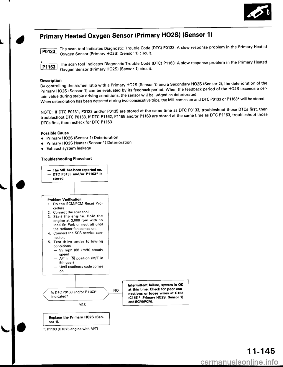
Primary Heated Oxygen Sensor (Primary HO2S) (Sensor 1l
The scan tool indicates Diagnostic Trouble Code (DTC) P0133: A slow response problem in the Primary Heated
Oxygen Sensor {Primary H02S) (Sensor 1) circuit.
The scan tool indicates Diagnostic Trouble code (DTC) Pl163: A slow response problem in the Primary Heated
Oxygen Sensor (Primary HO2S) (Sensor 1)circuit
Description
By controlling the airlfuel ratio with a Primary Ho2S {Sensor 1) and a secondary HO2S {Sensor 2), the deterioration of the
primary HO2S (Sensor 1) can be evaluated by its feedback period. when the feedback period of the Ho2s exceeds a cer-
tain value during stable driving conditions, the sensor will be judged as deteriorated
when deterioration has been detected during two consecutive trips. the MIL comes on and DTC P0133 or P1163* will be stored'
NOTE: tf DTC P0131, P0132 and/or P0135 are stored at the same time as DTC P0133, troubleshoot those DTCS first' then
troubleshoot DTC P0133. lf DTC Pl 162, P1168 and/or P1169 are stored at the same time as DTC P1163, troubleshoot those
DTCS first, then recheck for DTC Pl163.
Possible Cause
o Primary HO2S (Sensor 'l) Deterioration
o Primary HO2S Heater (Sensor 1)Deterioration
. Exhaust system leakage
Troublsshooting Flowchart
tFol3al
I P1163
- The MIL has been reported on- DTC P0133 and/or Pl163* is
stored,
Problem Verilication:1. Do the ECM/PCM Reset Pro
cedure-2. Connect the scan tool
3. Start the engine. Hold the
engine at 3,000 rpm with no
load (in Park or neutral) until
the radiator fan comes on
4. Connect the SCS service con-
nector.5. Test-drive u nder Iollowing
conditions.- 55 mph (88 km/h) steadyspeed- A/f in D position {M/T in
5th gear)
Until readiness code comes
lntermittent failure, 3Y3tem i3 OK
at thi3 time. Ch.ck lol Poor con-
ncctions or loosc wiros at C123
{C145)! lPrimary HO2S, Sensor 1l
and ECM/PCM.
Replace th6 Prim.ry HO2S (Sen'
sor 11.
*: P'l163 (D16Y5 engine with M/T)
11-145
Page 415 of 2189

PGM-FI System
Itil-"w Heated Oxygen Sensor (primary HO2S) (sensor 1l(Dl6Y5 engine with M/Tl
The scan tool indicates Diagnostic Trouble Code (DTC) p1162: A malfunction in the primary Heated OxygenSensor (Primary HO2S) (Sensor 1) circutt.
Doscription
The Primary Heated orygen sensor (Primary Ho2s) {sensor 1) operates over a wide airlfuel range. The primary Ho2S(Sensor 1) is installed in the exhaust manifold.
SEI{SORELEMENT
SENSORTERMINALS
ECM CONNECTOR C (31PIPRIMARY HO2S(SENSOR 1)8PCONNECTOR {Clir5)
female terminalsof femaleterminals
NOTE: lf DTC Pl162 is stored at the same time as DTC Pl167, troubteshoot DTC p1162 first, then recheck for DTC p1167.
(To page 11-147)
- lh6 MIL hes b6on reDorted on.- DTCPl162 ir 3tored.
Problom v6rificationi1. Do the ECM Reset Procedure.2. Start the engine.3. Wait at least tlvo minutes.
Test drive tor several miles withthe transmission in 3rd gear. Holdthe engine speed at 1,500 rpm.
ls DTC P1162 indicatod?
Intermittent tailuro, systom is OKat this timo. Check tor poor con-nections or loose wires at C145(Plimr.y HO2S, Senso. t) andECM,
ls DTC P1162 indicated?
Chock for an open in the wire(lP+ lins):1. Turn the ignition switch OFF.2. Disconnect ECM connector C{31P) from the ECM.3. Disconnect the 8P connectorfrom the Primary HO2S {Sen-sor 1).4. Check for continuity betweenthe Primary HO2S (Sensor 1)8P connector terminal No. 7and ECM connector terminalc23.
Repair open in the wire betwaonECM (C231 end Prim.ry HO2Slsen3or l).
Inspect lor poor terminal to termi-nal contact at the Primary HO2Slsensor 'l I connoctor and ECM.It terminal contect is OK, roplacelh6 Primrry HO2S {Sensor 1}.
11-146
Page 419 of 2189

PGM-FI System
l:in1.".fy Heated Oxygen Sensor (primary HO2SI (sensor 1l(D16Y5 engine with M/D (cont'd)
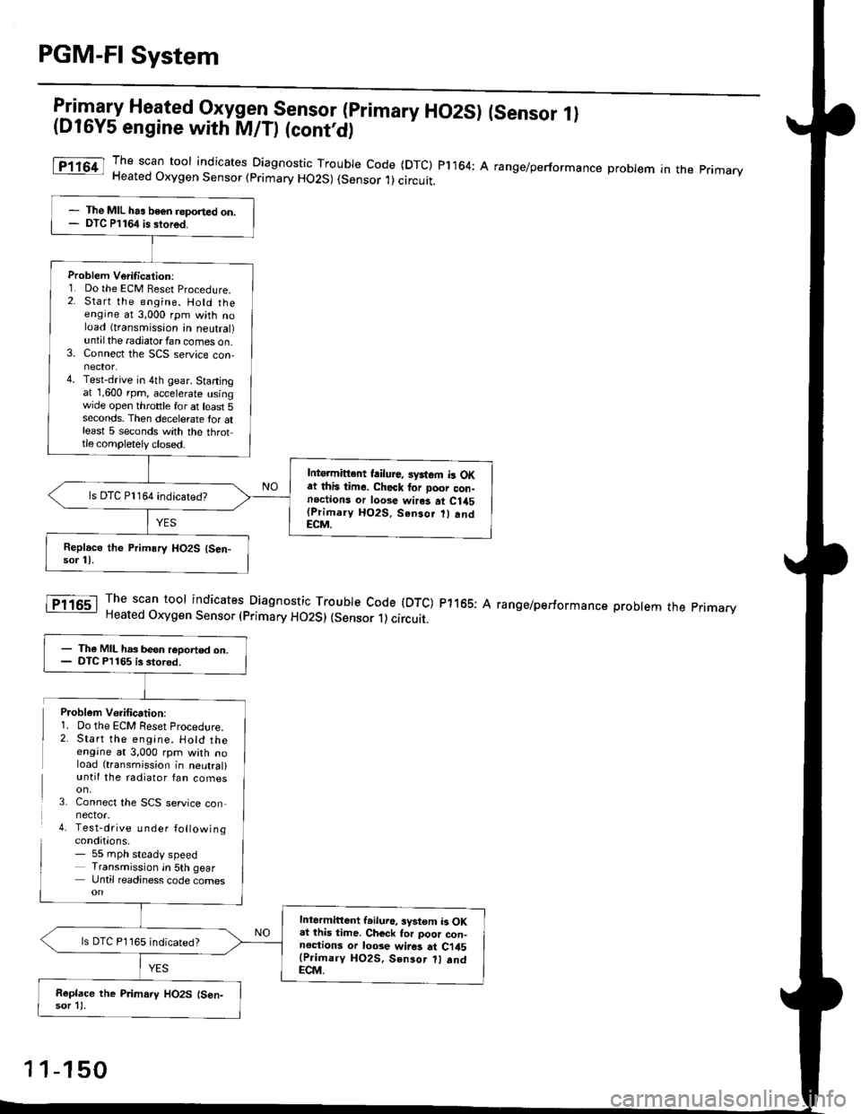
The scan toor indicates Diagnosti" -Tl:y|* code (DTC) pl164: A range/performance probrem in the primaryHeated Oxygen Sensor (primary HO2S) (Sensor 1)circuit.
The scan tool indicates Diagnostic Trouble Code (DTC) p1165: AHeated Oxygen Sensor (primary HO2S) (sensor 1) circuit.
range/performance problem the pnmarv
The MIL has beon reponed on.DTC P1164 is stored.
Problem Verilication:1. Do the ECM Beset Procedure.2. Start the engine. Hold theengine at 3,000 rpm with noload (transmission in neutral)untilthe radiatorfan comes on.3. Connect the SCS service con-nector.4. Test-drive in 4th gear. Startingat 1,600 rpm, accelerate usingwide open throttle for at least 5seconds. Then decelerate tor atleast 5 seconds with the throttle completely closed.
Intgrmittent failure, syrtem b OKat this time. Check tor Door con-noctions or loose wires at C1a5(Primary HO2S. Senso.
andECM.
ls DTC Pl164 indicatedT
- The MIL has been reoorted on.- DTC P1165 is stored.
Intermittent l.iluro, system b OKat lhis time. Ch€ck tor poor con-noctions or loose wir6 at Ci45(Prioary HO2S, Sen3or 1l .ndECM.
ls DTC P1165 indicated?
Replace the P.imary HO2S (S6n-sor 11.
Problem Vo.ification:1. Do the ECM Reset Procedlre.2. Start the engine. Hotd theengine at 3,000 rpm with noload (transmission in neutral)until the radiator fan comes
3. Connect the SCS service con,nector.4. Test-drive u nder followingconditions.- 55 mph steady speedTransmission in 5th gearUntil readiness code comes
1 1-150