Page 1957 of 2189

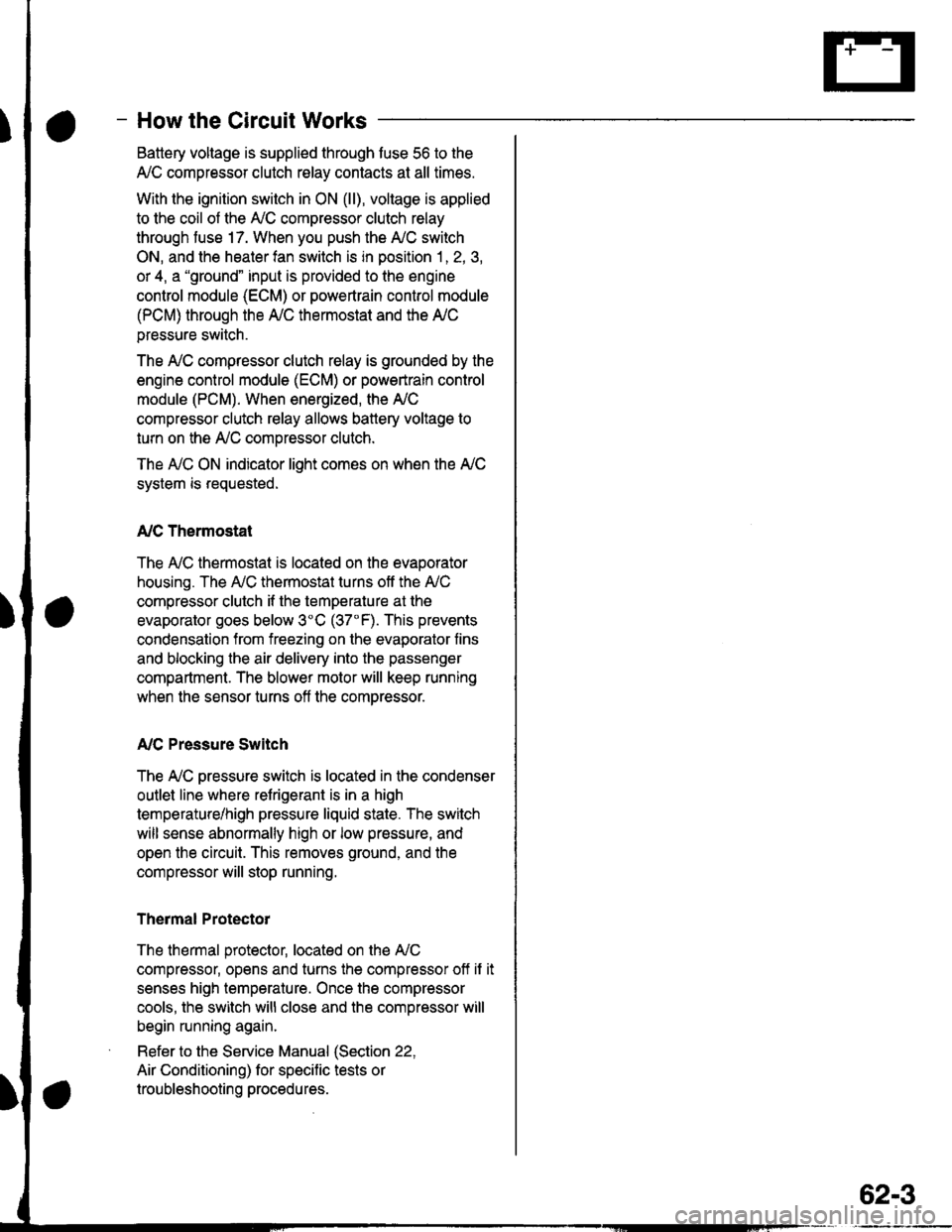
- How the Circuit Works
Battery voltage is supplied through tuse 56 to the
A,/C compressor clutch r€lay contacts at all times.
With the ignition switch in ON (ll), vollage is applied
to the coil of the A,/C compressor clutch relay
through fuse 17. When you push the A,/C switch
ON, and the heater fan switch is in position | , 2, 3,
or 4, a "ground" input is provided to the engine
control module (ECM) or powertrain control module
(PCM) through the l'lC thermostat and the l'lC
pressure switch.
The A,/C compressor clutch relay is grounded by the
engine control module (ECM) or powertrain control
module (PCM). When energized, the A'lC
compressor clutch relay allows battery voltage to
turn on the A,/C comDressor clutch.
The A,/C ON indicator light comes on when the A,/C
system is requested.
A,/C Thermostat
The A'lC thermostat is located on the evaoorator
housing. The A,/C thermostat turns off the A,/C
compressor clutch if the temperature at the
evaporator goes below 3'C (37'F). This prevents
condensation from freezing on the evaporator fins
and blocking the air delivery into the passenger
compartment. The blower motor will keep running
when the sensor turns off the comDressor.
A,/C Pressure Switch
The fuC oressure switch is located in the condenser
outlet line where refrigerant is in a high
temperature/high pressure liquid state. The switch
will sense abnormally high or low pressure, and
open the circuit. This removes ground, and the
compressor will stop running.
Thermal Protectot
The thermal protector, located on the A,/C
compressor, opens and turns the compressor off if it
senses high temperature. Once the compressor
cools, the switch will close and the compressor will
begin running again.
Refer to the Service Manual (Section 22,
Air Conditioning) for specific tests or
troubleshooting procedures.
62-3
Page 1962 of 2189
Rear Window Defogger
l
- '96-'98 Models
See Dash andConsole Lights
rf
See Dash andConsole Lights
S€e GroundDistribution,page 14-7.
L--------
c501
vtEw 55
il
l1c
FUSE 16FR DEF R€LAY7_54
I FUSE/RELAY
ff":;;1il, l"'3|""
3"C3jgl-i
REARwtNDowDEFOGGERSWITCH
.I UNDER-DASH
@
r-F----1
i-f:"'*rul
!._L:___J
UNDER-HOODFUSE/RELAYBOX
FEO/BL|
vtEw 34
ll-,---:L::
NEAHwtNDowDEFOGGERRELAYP|1oTO 59
UNOER-DASHFUSE/RELAYBOX
co,pe ano seoanu
'1"[ FzT;4-
-------J
Hatchback
See GroundDistribution,page 14-7.
Y
I
I
t___
"._,".trf
t*''
T^
fl[lfEex,"
"'-f
t
seecrounda rr( Distnbutron,
"r- |
Pase 14-10
I
* coorPHA|O 1A2
".^,"i'uI g"x%,0,
' * 9,g%,,,eu,eul
I
|.Tl neanI .5 | WTNDOW
IiIDEFoGGER
I"
I*-l
II ^--.
PHOra 1AA: G401
64
Page 1965 of 2189
Integrated Control Unit
NOTE: Fuse 31 is hot with lgnition Switch in START (lll) and clutch pedal depressed or A,/T Gear Selector in
PARK (P) or NEUTRAL (N), see Starting System, page 21,21-1, ot 21-2.
See BrakeSystemlndicatorli^hl
FUSE 3IstaaTEaSIGI{AT7AAI
I
I
I
I
I
\
\
\
\
\
\
I
I
I
I
I
I
/
S€s SiarlingSyslsm, pago 21,21-1. or 21'2.
SEs BrakeSystemlndicetorLight A6
SsaClharSrrESystom
Eog GoundDistlbution,page l,l-7.
L------3c420PHO|O 63vtEw 53
--r-r..r'
FED/BLU
SeeCeilingLightSee Seat Beltand lgnitionKey Remind€rs
t@
i'l-;;,-lH8B'r*| rrmn1gn I FUSEI
i f t*" ig8f"LJr____J PHOTO 7
u'lf tf,%,
S vtEw 3a
wHr/FED
| 3fl3,n'"n
wHr,FED I sYsteh
<--=- !t
,r"r,".0 | ,n"r,".u I
| .l B*?r:"" ,.!,.*,
Page 1967 of 2189

Brake System Indicator Light
- '96-'98 Models
NOTE: Fuse 31 is hot with lgnition Switch in START (lll) and clutch pedal depressed or A,/T gear selector in
PARK (P) or NEUTRAL (N), see Starting System, page 21 , 21-1, or 21-2.
a
FUS€ 31atAirEn8Gl{tt7.all
UNDER-DASHFUSE/RELAYBOXS€o Starling Sysl6m,pag6 21, 2l-1, or el-2,
FUSE 25
ffR s." Ponr"tDistribulion,page 10-6.
rry
I
;?l
r
I
I
I
I
I
I
I
c501PHOTO 60vtEw 55
Ss€ Pow6rDlstribution,page 1G6.
---.I GAUGE$os IndicatorsI ASSEMBLY
i',i!i,I2'
I
I
(slt--95.:l-_i
l8s: GRN/FEDr--- CW ----.
! 3 A cso3 :..^.,"..,"",^.;i "lir%?u' ' rRANsMls-sloN :! ll virw ro : CONTROL ;
99€ grqn'd | ! s I iiiiir^ , vtLw 6s
i o"^r"'o |
'i'jri
| "lw;t,b---4---- 31i3*:'. --l:ffiffi--i
i
---- -.L- J- -:g,tgLesr.l - ---- J--:- J--i : ! 3113'"0* | :-9tF":--T-tY-E;"41i'",
: : lsrss9l;-;?--q1Al" :L:W-J i
-----.1- J- -tlb$Lsr'{.i------ J--:- J--i : ! 31ffi "o* | i-trfr; - -
i
-TFr,lifu:i-|l - - .Tf"*;',r;,f'.F?f;l', i LTS-: :
i I ii
-""'"L--i:t--i3trFlr*n'"i
i mooule ficlrt) iI PHO|O 121 '
:! :i ffitre"ninas;: ll ti n"",".0 ll :---. [: i,119i9."' ''tl
: I :i asi: '.I i eri: -----':::---:
i",",1 iiiffi_il$.t'ii: i"-,s*
vlEw 54
-- vtEot 66 , Ffl anlxe rLUto
i*l
' ".","1;l,"p;a;
illJff*ttt**
u.-u.*il ii [JFHi:"'l*iTfit*,".
I Y i frpanxrxc :' r#"Al[';u3*'""i
I I
U il4.lFfffff'UJ:"" ii EJi,fii,i,"-" i r-j
3"ilj*il
ii
"."""J[ft*,,tl-
i lilt:','x;l
71
i Cior I tE^- phoroTs ,l - : pHoro 7s * C+6tF6r6sz r- usA. - - - - - . t - - - - - canada Froiit sz
Page 1969 of 2189

Brake System Indicator Light (cont'd)
- How the Circuit Works
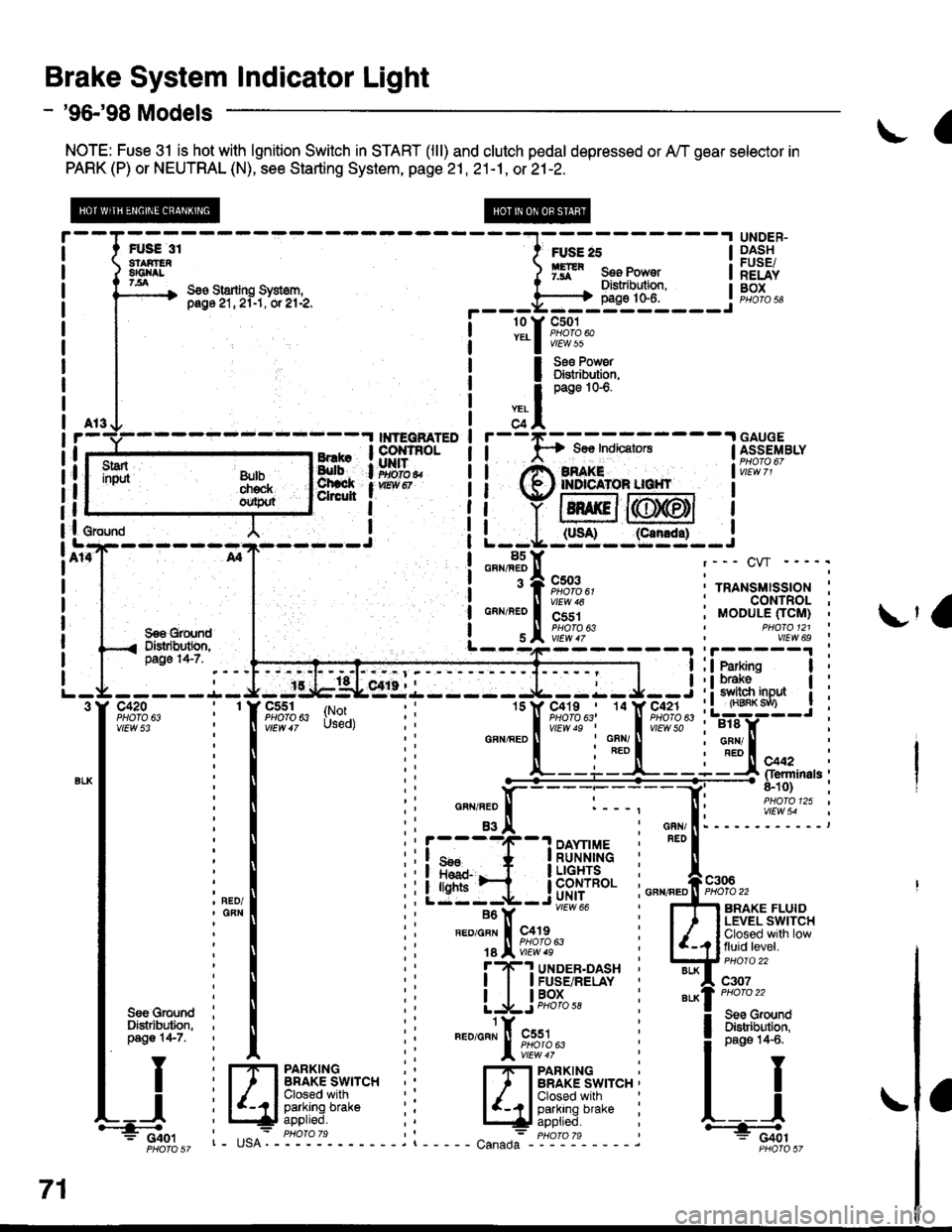
The brake system indicator light comes on to alert
the driver that the parking brake is applied, or that
the brake fluid level is low. lt also comes on as a
bulb test when the engine is cranked.
Parking Brake
With the ignition switch in ON (ll) or START (lll),
voltage is applied through fuse 25 to the brake
system light. When you apply the parking brake, the
switch closes and provides a ground for the light.
The light then comes on to remind you that the
parking brake is applied.
Brake Fluid Level
With the ignition switch in ON (ll) or START (lll),
voltage is applied through fuse 25 to the brake
system light. lf the brake fluid level is low, the brake
fluid level switch closes, providing ground to the
circuit. The brake system light then comes on,
alerting the d verto a low brake fluid level in the
brake master cylinder. (Check brake pad wear
before you add fluid).
Bulb Check
With the ignition switch in START (lll) and clutch
pedal depressed or A'lT gear selector in PARK (P)
or NEUTRAL (N), voltage is applied through fuse 31
to the brake bulb check circuit. The brake bulb
check circuit closes, allowing current to flow through
the brake system light and bulb check circuit to
ground. The brake system light then comes on to
test the bulb.
Refer to the Service Manual (Section 23, Electrical)
for specific tests or troubleshooting procedures.
71-2
a
\fa
Page 1971 of 2189
How the Circuit Works
Seat Belt Warning
With the ignition switch in ON (ll) or START (lll),
battery voltage is applied to the seat belt reminder
light. When the seat belt is not buckled, the seat
belt reminder/key-on beeper circuit in the
integrated control unit senses ground through the
closed seat belt switch. The seat belt reminder light
comes on and stays on, and the beeper beeps for
6 seconds. The reminder light and beeper will stop
when the seat belt is buckled or the timer circuit
deactivates them.
lgnition Key Warning
Battery voltage is supplied at all times to the seat
belt reminder/key-on beeper circuit in the
integrated control unit. When you turn on the
ignition key switch the integrated control unit
senses ground. lf you open the driver's door, the
door switch closes, causing the beeper to sound
until the door is closed.
Refer to the Service Manual (Section 23, Electrical)
for specitic tests or troubleshootrng procedures.
73-1
Page 1972 of 2189
Low Fuel Indicator Light
l
't
I
I
I
IJ
pag6 106.
,
-ls,T,*-*:lligff*,
l',;l:'l?,'
A3A
!'-{ilril}-1 PowERTRAtNI Lowtuel I CONTROL
I i$grtor I MoD]LE (pcM)
i
S' i18l7"*
UNDER.DASHFUSE/RELAYBOXPHOTO 58
!ra
or*+* i
TFI i
--l------i"I
I
A oxc€pt GX
c503PHO|O 61
AFN/GFI{
9FN/GBN
15
BLU/FEO
c410
vlEw 3s
c'131PHO|O A5vtEw 59
I TANK: UNITThan|tlrlor
So€qauges
L-----J- ----J
Sae GroundDistribution,pa$ 14-9.
74
Page 1973 of 2189

How the Gircuit Works
All Except GX
Do not smoke while working on the fuel system.
Keep open flame away trom the work area. Drain
fuel only into an approved container.
A thermistor is mounted in the fuel tank unit. When
the thermistor is cool, its resistance is very high.
When the thermistor's temperature increases, its
resistance decreases. Fuel in the fuel tank transters
heat away lrom the thermistor fast enough to keep it
cool so the thermistor's resistance stays high and
lhe low fuel indicator light does not come on. When
the fuel level drops below the thermistor, the
thermistor's temoerature increases. Without the fuel
to cool it, the thermistor's resislance decreases,
allowing current to llow through the low fuel
indicator light and the thermistor to ground, and the
low fuel indicator light comes on.
Refer to the Service Manual (Section 23, Electrical)
for specific tests or troubleshooting procedures.
GX
The PCM turns on the low fuel indicator light when
the fuel level is low. The PCM will also blink the
indicator light when a problem is detected by the
fuel tank pressure sensor or the fuel tank
temperature sensor.
Refer to the Service Manual GX Supplement
(Section 11 , Fuel and Emissions) for specific tests
or troubleshooting procedures.
74-1