Page 1535 of 2189

lr-
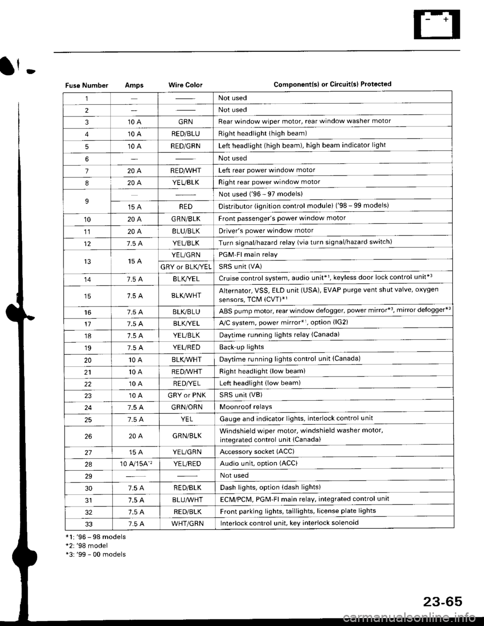
Fuse NumberAmpswire ColorComponent{sl or Circuit(sl Protected
*1r '96 - 98 models*2r '98 model*3: '99 - 00 models
,lNot used
2Not used
310 AGRNRear window wioer motor, rear window washer motor
410 ARED/BLURight headlighr thigh beam)
510 ARED/GRNLeft headlight (high beam), high beam indicator light
6Not used
7204R E D/VVHTLeft rear power window motor
820A.YEUBLKRight rear power window motor
9Not used ('96 - 97 models)
't5 AREDDistributor (ignition control module) ('98 - 99 models)
10204G RN/BLKFront passenger's power window motor
1120ABLU/BLKDriver's power window motor
127.5 AYEUBLKTurn signal/hazard relay (via turn signal/hazard switch)
t515 AYEL/GRNPGM-Fl main relay
GRY or BLK,^/ELSRS u nit (VA)
141.54B LK/YE LCruise control system, audio unit*1, keyless door lock control unit*3
BLK/lr'r'HTAlternator, VSS, ELD unit (USA), EVAP purge vent shut valve, oxygen
sensors, TCM (CVT)*'
t6BLI(,/BLUABS pump motor, rear window defogger. power mirror*3, mirror delogger*3
177.5 ABLK,/YE LA,/C system, power mirror*r. option (lG2)
18YEUBTKDaytime running lights relay (Canada)
197.5 AYEUREDBack'up lights
2010ABLK/VVHTDaytime running lights control unit (Canada)
2110 AREDA/VHTRight headlight (low beam)
2210 ARE DI/E LLeft headlight (low beam)
10 AGRY or PNKSRS UNit (VB)
247.5 AGRN/ORNMoonroof relays
257.5 AYELGauge and indicator lights. interlock control unit
204GRN/BLKWindshield wiper motor, windshield washer motor,
integrated control unit {Canada)
15 AYEL/GRNAccessory socket (ACC)
2a10 A,/'�]5A''YE L/R EDAudio unit, option (ACC)
29Not used
307.5 AR ED/BLKDash lights, option (dash lights)
1.5 ABLUA/VHTECM/PCl\4, PGM-Fl majn relay, integrated control unit
RED/BLKFront parking lights, taillights, license plate lights
337.5 AWHT/GRNlnterlock control unit. key interlock solenoid
23-65
Page 1575 of 2189

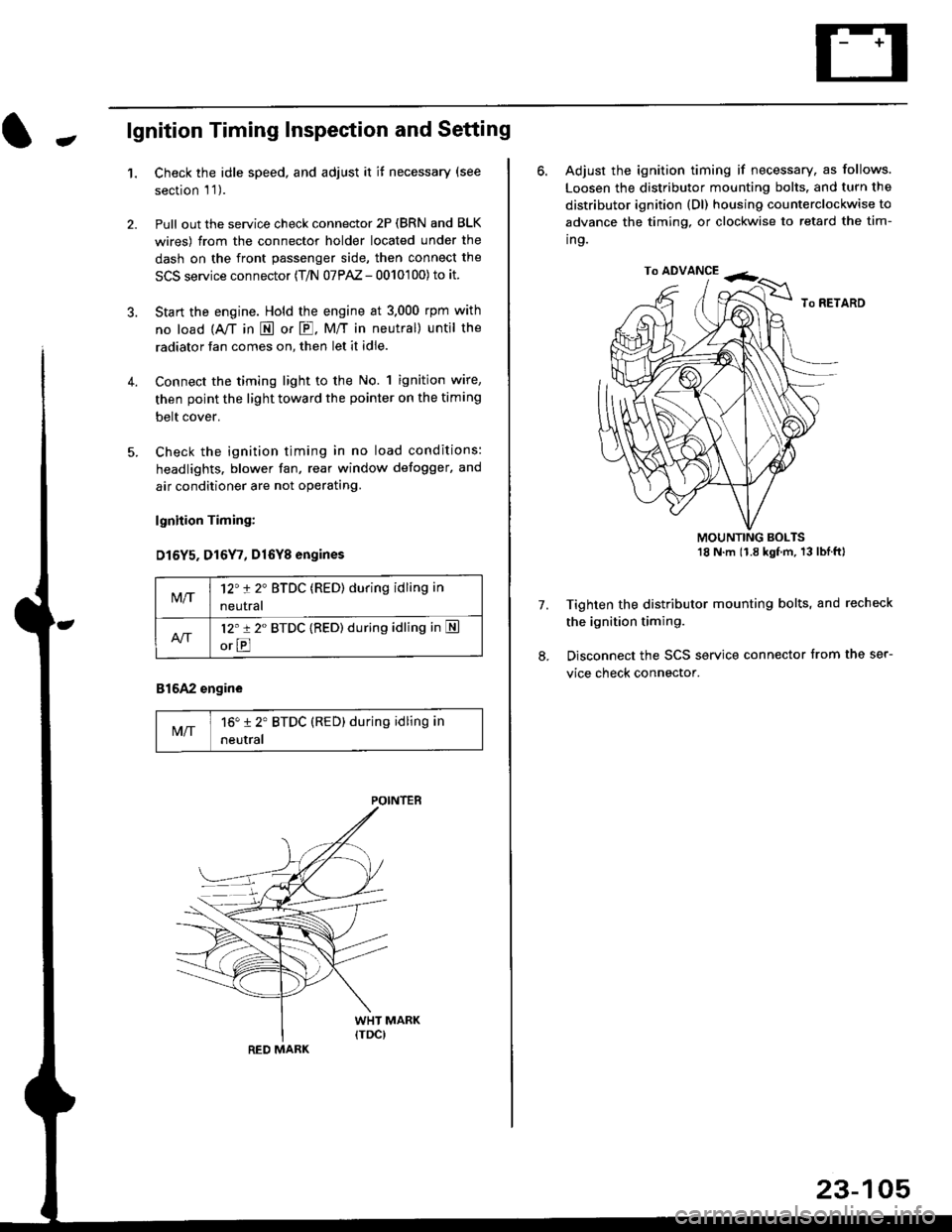
-lgnition Timing Inspection and Setting
1.Check the idle speed, and adjust it it necessary (see
section 'l '1 ).
Pull out the service check connector 2P (BRN and BLK
wires) from the connector holder located under the
dash on the front passenger side, then connect the
SCS service connector (T/N 07PAZ - 0010'100) to it.
Start the engine. Hold the engine at 3.000 rpm with
no load {A,/T in E or E. M/T in neutral) until the
radiator fan comes on, then let it idle.
Connect the timing light to the No. 1 ignition wire,
then point the light toward the pointer on the timing
belt cover.
Check the ignition timing in no load conditions:
headlights. blower fan, rear window defogger, and
air conditioner are not operating.
lgnhion Timing:
D15Y5. D16Y7, Dl6Yg engines
816A2 engine
MIT16" 12' BTDC (RED) during idling in
neutral
M/T12't 2" BTDC (RED) during idling in
neutral
l2'r 2" BTDC {RED) during idling in S
orE
POINTEB
RED MARK
23-105
ro ADVANCE -<;,
6. Adjust the ignition timing if necessary, as follows.
Loosen the distributor mounting bolts. and turn the
distributor ignition (Dl) housing counterclockwise to
advance the timing, or clockwise to retard the tim-
ing.
MOUNTING BOLTS18 N'm (1.8 kgfm, 13lblftl
Tighten the distributor mounting bolts, and recheck
the ignition timing.
Disconnect the SCS service connector from the ser-
vice check connector.
7.
Page 1576 of 2189

lgnition System
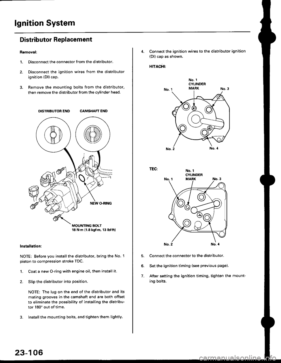
Distributor Replacement
Removal:
1. Disconnect the connector from the distributor.
2. Disconnect the ignition wires from the distributor
ignition {Dl) cap.
3. Remove the mounting bolts from the distributor,
then remove the distributor from the cylinder head.
DISTRIBUTOR END CAMSHAFT END
MOUNTING BOLT18 N.m 11.8 kgtm, 13lbf.ltl
lnstallation:
NOTE: Before you install the distributor. bring the No. 1
piston to compression stroke TDC.
1. Coat a new O-ring with engine oil, then install it.
2. Slip the distributor into position
NOTE: The lug on the end of the distributor and its
mating grooves in the camshaft end are both offset
to eliminate the possibility of installing the distribu-
tor 180" out of time.
3. Installthe mounting bolts, and tighten them lightly.
23-106
4, Connect the ignition wires to the distributor ignition
(Dl) cap as shown.
rracfit'
No. 1CYLINDERMARK
No. 1CYLINDER
TEG:
5.
6.
7.
No. 2No. a
Connect the connector to the distributor.
Set the ignition timing (see previous page).
After setting the ignition timing, tighten the mount-
ing bolts.
Page 1577 of 2189
el -Distributor Overhaul
HITACHI:
TOC/CKP/CYP
DISTRIBUTOR IGNITION {DI} HOUSINGCheck for cracks and damage.
Troubleshooting, section 1 1
Do not disassemble.
CAP SEALCheck for damage.
IGNITION CONTROL MODULE (ICMI
Input Test, page 23'109
IGNITION {DI) CAP
Check for cracks, wear,damage, and fouling.Clean or replace,
{cont'd)
23-107
Test, page 23_110
Page 1578 of 2189
lgnition System
Distributor Overhaul (cont'dl
TEC:
IGNITION CONTROLMODULE IICM'Input Test, page 23-1
DISTRIBUTOR IGNITION {DI} HOUSINGCheck for cracks and damage.
COVER
DISTRIBUTOR IGNITION IDI) ROTOB
CAP SEALCheck for damage.DISTRIBUTOR IGNITION {DII CAPCheck for cracks, wear,damage, and fouling.Clean or replace,
IGNITION COILTest, page 23-110
O-RINGReplace
\
I
@
TDC/CKP/CYP S€NSORTroubleshooting, section 1 1Do not disassemble.
WHT/BLU
23-104
Page 1579 of 2189

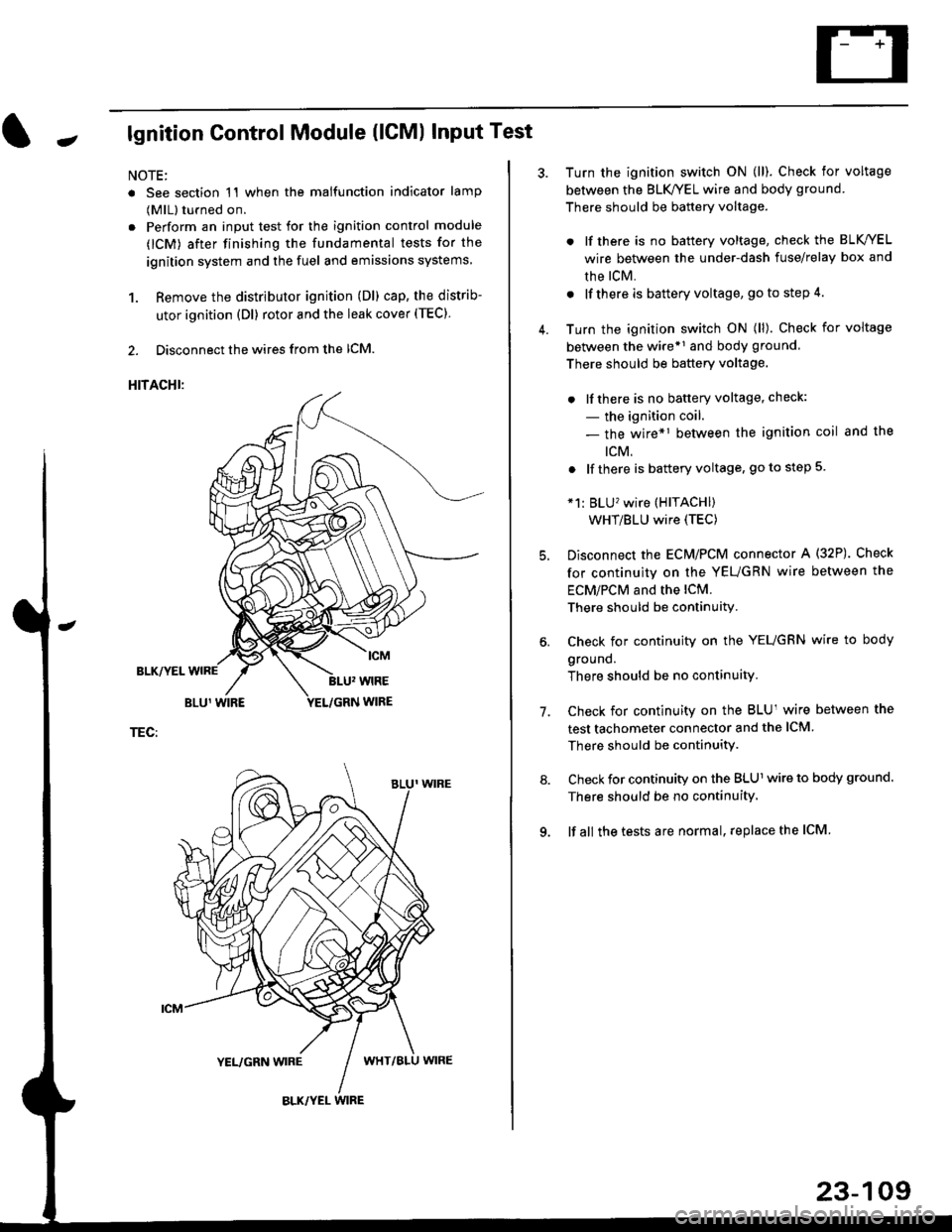
Jlgnition Control Module (lCMl Input Test
NOTE:
. See section 1'l when the malfunction indicator lamp
(MlL) turned on.
. Perform an input test for the ignition control module
(lCM) after finishing the fundamental tests for the
ignition system and the fuel and emissions systems
1. Remove the distributor ignition (Dl) cap, the distrib-
utor ignition (Dl) rotor and the leak cover (TEC).
2. Disconnect the wires from the lCM.
HITACHI:
BLK/YEL
TEC:
Turn the ignition switch ON (ll). Check for voltage
between the BLK/YEL wire and body ground.
There should be battery voltage.
. lf there is no battery voltage, check the BLK/YEL
wire between the under-dash fuse/relay box and
rhe lcM.
. lf there is battery voltage, go to step 4.
Turn the ignition switch ON (ll). Check for voltage
between the wire*r and body ground
There should be battery voltage.
. lfthere is no battery voltage, check:
- the ignition coil.
- the wire*1 between the ignition coil and the
tcM.
. lf there is battery voltage, go to step 5
*1: BLU'�wire (HITACHI)
WHT/BLU wire (TEC)
Disconnect the EcM/PCM connector A (32P). Check
for continuity on the YEUGRN wire between the
ECM/PCM and the lCM.
There should be continuity.
Check for continuity on the YEUGRN wire to body
ground.
There should be no continuity.
Check for continuity on the BLUl wire between the
test tachometer connector and the ICM
There should be continuitY.
Check for continuity on the BLUl wire to body ground.
There should be no continuity.
lf all the tests are normal, replace the ICM
7.
23-109
Page 1872 of 2189
, r -.-- .l TBANSMTSS|ON
I igF"![E#'
:. lr-ri";l:';9""
POWERTRAINor ENGINECONTROL MODULE(PCM or ECM)PHO|O 86
lgoitionoutEltofl-
YEUGFN
c'l20
TESTTACHOMETEBCONNECTOR
DISTRIBUTOR
.I GAUGEI ASSEMBLY
iw,tr?,'
I
IJ
BIU
9
ALU
BLU
c120
vtEw 29
c101
vtEw 28
'. Y F,fl}l.BLU I viEw 60
cel
i i:*bi
rA*oxErEn
irlg:lL----- ----
20-1
Page 1874 of 2189
POWEBTRAINor ENGINECONTROL MODULE(PCM or ECM)
vtEw 70
lgnitionoulputsignatflcM)
I
YEUGBN
c'120
vtEw 29
DISTRIBUTOR
D1685 -------,
BLU
_9-
BLU
8
9LU
:'!'\?- - -
c101
vtEw 2a
----------<- c442
I frerminals 1-4]a|-u a olo'25 |I vlEw 54
19 g C411a PHOTA 60aru I vtrw ool,cBA- -.t GAUGF
i f#f rAcHoirErER ift?i,?""i
liitr" i !I L--J IL ---- - --- -J
TESTTACHOMETERcor.rNEcToRPHO|O2l
lgniiionnrpur Fh^ih-signal "p_il;Ground output
PrimaryoutPutcontsol
20-3