Page 1199 of 2189

Anti-lock Brake System (ABSI
Featu res/Construction
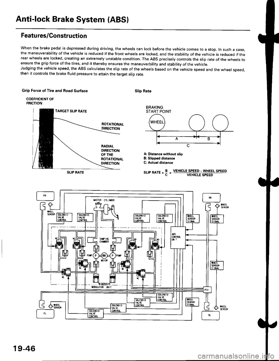
When the brake pedal is depressed during driving, the wheels can lock before the vehicle comes to a stop, In such a case,the maneuverability of the vehicle is reduced if the front wheels are locked, and the stability of the vehicle is reduced if therear wheels are locked, creating an extremely unstable condition. The ABS precisely controls the slip rate of the wheels toensure the grip force of the tires. and it thereby ensures the maneuverbility and stability of the vehicle.Judging the vehicle speed. the ABS calculates the slip rate of the wheels based on the vehicle speed and the wheel speed,then it controls the brake fluid pressure to attain the target slip rate.
Grip Force of Tire and Road Surlace
COEFFICIENT OFFRICTION
TARGET SLIP RATE
Slip Rate
BRAKINGSTART POINT
ROTATIONALDIRECTION
RADIALDIRECTIONOF THEROTATIONALOIRECTION
A: Distance without slio8: Slippsd distanceC: Actuel distance
sr-rrmre=f=SLIP RATEVEIIICLE SPEED - WHEEL SPEEOVEHICLE SPEED
19-46
Page 1201 of 2189

Anti-lock Brake System {ABS)
Operation (cont'dl
ABS Modulator
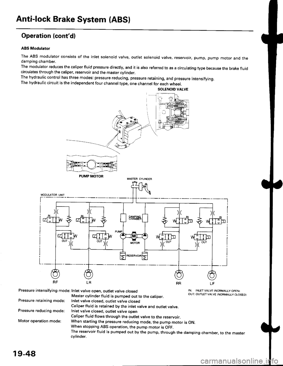
The ABS modulator consists of the inlet solenoid valve, outlet solenoid valve, reservoir, pump, pump motor and thedamping chamber.
The modulator reduces the caliper fluid pressure directly, and it is also referred to as a circulating type because the brake fluidcirculates through the caliper, reservoir and the master cylinder.The hydraulic control has three modes: pressure reducing, pressure retaining, and pressure intensifying.The hydraulic circuit is the independent four channel type, one channel for each wheel.
RF LR
Pressure intensifying mode: Inlet valve open, outlet valve closed
Pressure retaining mode:
Pressure reducing mode:
Motor operation mode:
rN: INLETVALVE {NORMALtY OpENIOUT: OUTIET VALVE {NORMALIY CTOSED)Master cylinder fluid is pumped out to the caliDer.Inlet valve closed, outlet valve closedCaliper fluid is retained by the inlet valve and outlet valve.Inlet valve closed, outlet valve oDenCaliper fluid flows through the outlet valve to the reservoir.When starting the pressure reducing mode, the pump motor is ON.When stopping ABS operation, the pump motor is OFF.The reservoir fluid is pumped out by the pump, through the damping chamber, to the mastercvlinder.
PUMP MOTOR
19-48
Page 1233 of 2189
l}
GLASSReplacement,page 20 6Adiustment,page 20-20GLASS RUNCHANNEL
CENTER LOWERCHANNEL
eCYLINDERPBOTECTORREGULATORReplacement,page 20-6LOCK RODPROTECTOR
STRIKER 'Adjustment, llpage 20-23
tt t[
#-l|r&
/h)
/Y
LATCHReplacement,20-6
LOCKCYLINOERRETAINERCLIP
^o
?'2'
ourER HANoLE
ecuLaron
HANOLE
POWER DOORLOCK SwlTCH(driver's only)
Replacement, page 20-5
INNEN HANDLE ROD
LATCHPROIECTOR
-) /
s/
*Nqd'
/ -"-/
tt\
. '\
It
INNERHANDLE
20-3
Page 1235 of 2189
\:Outer Handle Replacement
NOTE: Raise the glass fully.
'1. Remove:
. Door panel
. Plastic cover (see page 2o-21
2. Pull out the retainer cliP.
6x1.omm Ii.e N.. tr.o rgf.-, I7.2 rbr.fi) ,2
C3.
CYLINDER PROTECTOR
LOCK CYLINDEB
RETAINERCLIP
Remove the bolts, then remove the cylinder protec-
tor, lock cylinder and outer handle.
>: Bolt locaiions,2
CYLINDER
LOCK CYLINDER
CYLINDER ROD
20-5
4. Pull out the outer handle. Pry the outer handle rod
out of its joint using diagonal cutters
NOTE:
a To ease reassembly, note location @ of the outer
handle rod on the joint before disconnecting it.
. Take care not to bend the outer handle rod.
o Use a shop towel to protect the opening in the
ooor.
OUTER HANDLEROD
DIAGONALCUTTERS
SHOPTOWEL
lnstallation is the reverse of the removal procedure
NOTE: Make sure the door locks and opens properly.
BUSHINGReplace.
\
,w.
5.
i4'
Page 1236 of 2189

Doors
Latch Replacement
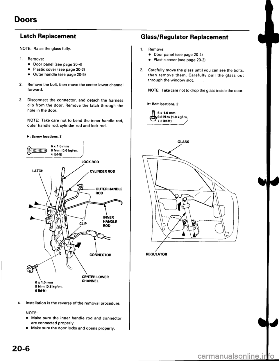
NOTE: Baise the glass fully.
1. Remove:
. Door panel (see page 20-4)
. Plastic cover (see page 20-2). Outer handle (see page 20-5)
Remove the bolt, then move the center lower channel
forwa rd.
Disconnect the connector, and detach the harness
clip from the door. Bemove the latch through the
hole in the door.
NOTE: Take care not to bend the inner handle rod,
outer handle rod, cylinder rod and lock rod.
>: Screw locations, 3
6 x 't.0 mm8 N.m (0.8 kgt m,6 tbf.ftl
4. Installation is the reverse of the removal procedure.
NOTE:
. Make sure the inner handle rod and connector
are connected properly.
. Make sure the door locks and opens properly.
LOCK ROO
20-6
'1.
Glass/Regulator Replacement
Removel
o Door panel (see page 20-4)
. Plastic cover (see page 20-2l,
Carefully move the glass until you can see the bolts,
then remove them. Carefully pull the glass out
through the window slot.
NOTE: Take care not to drop the glass inside the door.
>i Bolt loc.tions,2
fi s'r.o-. iClb9.8 N.m 11.0 kst m,l
_-l't!!t ,/
GLASS
REGULATOR
Page 1239 of 2189
\L
lJ\
\flREAR CHANNEL N\
\,\
\
\i\Ill
ld 1l
6P lll
REo" c"AN"..: | 1lcoLLAR J I
)€)\IJ
6/
\3-
REGULATORHANOLE
:& fr\
r lll'All criss lLl
l'A sroeeen lll
W-*d
t a)" u\
*)u*ro* \
Repracement, pase 20 ,tt
l5[1tfCHANNEL
OUTER HANDLEReplacement, Page 20-11
STRIKERAdjustment,page 20'23
I
I
%grc
POWER WINDOWMOTOR
LOCK RODPROTECTOR
LATCHPROTECTORReplacement,page 20-12
POWER OOORLOCK ACTUATOE
t
20-9
Page 1241 of 2189
tOuter Handle Replacement
NOTE: Raise the glass fullY.
1. Remove:
. Door panel
. Plastic cover (see page 20-8)
2. Remove the screws.
>: Screw locations, 3
6x1.0mm6 N.m {0.6 kgf m,4 tbf.ftl
a\
3. Move the latch down, and remove the bolts.
>: Bolt locations,2
6x1.0mm9.8 N,m )11.O kst.n,7.2lbiftl //
4. Pull out the outer handle. Pry the outer handle rod
out of its joint using diagonal cutters.
NOTE:
. To ease reassembly, note location O of the outer
handle rod on the joint before disconnecting it.
. Take care not to bend the outer handle rod.
. Use a shop towel to protect the opening in the
door.
BUSHINGReplace.
OUTERHANDLEROD
5.
o
DIAGONAL \
:"'* ,w,
lnstallation is the reverse of the removal procedure
NOTE: N4ake sure the door locks and opens properly.
SHOP TOWEL
20-11
Page 1242 of 2189

Doors
Latch Replacement
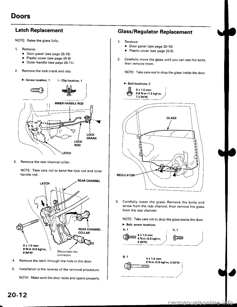
NOTE: Raise the glass futty.
1. Remove:
. Door panel (see page 20-10). Plastic cover (see page 20-8). Outer handle (see page 2O-1 ,l
2. Remove the lock crank and clip.
>: Screw location, I >: Clip location, I
qn@l # |
_ __) _-__)
LOCKROO
LATCH
Remove the rear channel collar.
NOTE: Take care not to bend the lock rod and innerhandle rod.
Disconnect theconnector.
6x1.0mm8 N.m (0.8 kgt m,
5.
6 tbtttl
Remove the latch through the hole in lne door.
lnstallation is the reverse of the removat proceoure.
NOTE: Make sure the door locks and opens properly.
20-12
,,< 8 N.m to.8 ksf.m, 6 tbt.ftt
IDF-IIID I
.)-__,/
2.
L
p o'r.o-,n I@ 9.8 N.m {t.o kof.m. I
.- :'zulnt -
/
3. Carefully lower the glass. Remove the bolts andscrew from the rear channel, then remove the glassfrom the rear channel.
NOTE: Take care not to drop the glass inside the door.
>: Bolt. screw locations
A, 1 , c, 1I
q)h:iT(--n,,". i m
- - illt) '/ -)
Glass/Regulator Replacement
Remove:
. Door panel {see page 20-10). Plastic cover (see page 20,8)
Carefully move the glass until you can see the bolts,then remove them.
NOTE: Take care notto drop the glass inside the door.
>: Eolt locations, 2
6x1.0mmB, 1