Page 886 of 2189

Description
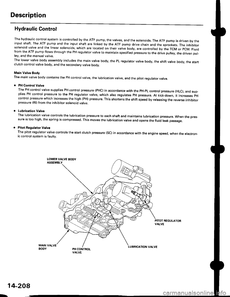
Hydraulic Control
The hydraulic control system is controlled by the ATF pump. the valves, and the solenoids. The ATF pump is driven by theinput shaft. The ATF pump and the input shaft are linked by the ATF pump drive chain and the sprockets, The inhibitorsolenoid valve and the linear solenoids. which are located on their valve body, are controlled by the TCM or pcM. Fluidfrom the ATF pump flows through the PH regulator valve to maintain specified pressure to the drive pulley, the driven pul-ley, and the manual valve,
The lower valve body assembly includes the main valve body, the PL regulator valve body, the shift valve body, the startclutch control valve body, and the secondary valve bodv.
Main Valve Eody
The main valve body contains the pH control valve, the rubrication valve, and the pitot regulator valve.
PH Control Valve
The PH control valve supplies PH control pressure (PHCI in accordance with the pH-pL control pressure (HLc), and sup-plies PH control pressure to the PH regulator valve, which also regulatss PH pressure. At kick-down, it increases pHcontrol pressure which increases the high (PH) pressure. This shortens the shift speed by releasing the reverse inhibitorpressure (Rl)from the inhibitor solenoid valve.
Lubrication Valve
The lubrication valve controls the lubrication pressure to each shaft and maintains lubrication pressure. When rne pres-sure is too high, the spring is compressed. This moves the lubrication valve and opens the fluid leak passage.
Pitot Regulalor Valv6
The pitot regulator valve controls the start clutch pressure (SC) in accordance with the engine speed, when the electron-ic control system is faulw.
MAIN VAIVEBODY
L.
14-208
Page 887 of 2189

Secondary Valve Body
The secondary valve body contains the PH regulator valve. the clutch reducing valve' the start clutch valve accumulator'
and the shift inhibitor valve
PH Regulator Valve
The pi regulator valve maintains hydraulic pressure supplied from the ATF pump. and supplies PH pressure to the
hvdraulic control circuit and the lubrication circuit. PH pressure is regulated at the PH regulator valve by the PH control
pressure (PHC) from the PH control valve.
Cluteh Reducing Valvo
The clutch reducing valve receives PH pressure from the PH regulator valve and regulates the clutch reducing pressure
(cR). The clutch reducing valve supplies clutch pressure (cR) to the manual valve and the start clutch control valve' and
supplies signal pressure to the PH-PL pressure control valve. the shift control valve, and the inhibitor solenoid valve'
Start Clutch Valv€ Accumulator
The start clutch vatve accumutator stabilizes the hydraulic pressure that is supplied to the start clutch'
Shift Inhibitor Valve
The shift inhibitor valve switches the fluid passage to switch the start clutch control from electronic control to hydraulic
control when the electronic control system is faulty. lt also suppliss clutch reducing pressure (cR) to the pitot regulator
valve and the pitot lubrication pipe.
START CLUTCH VALVE
SECONDARY VALVEBODY
SHIFT INHIBITOE VALVE
(cont'd)
PH REGULATOR VAL
REDUCING VALVE
14-209
Page 888 of 2189

Description
Hydraulic Control {cont'dl
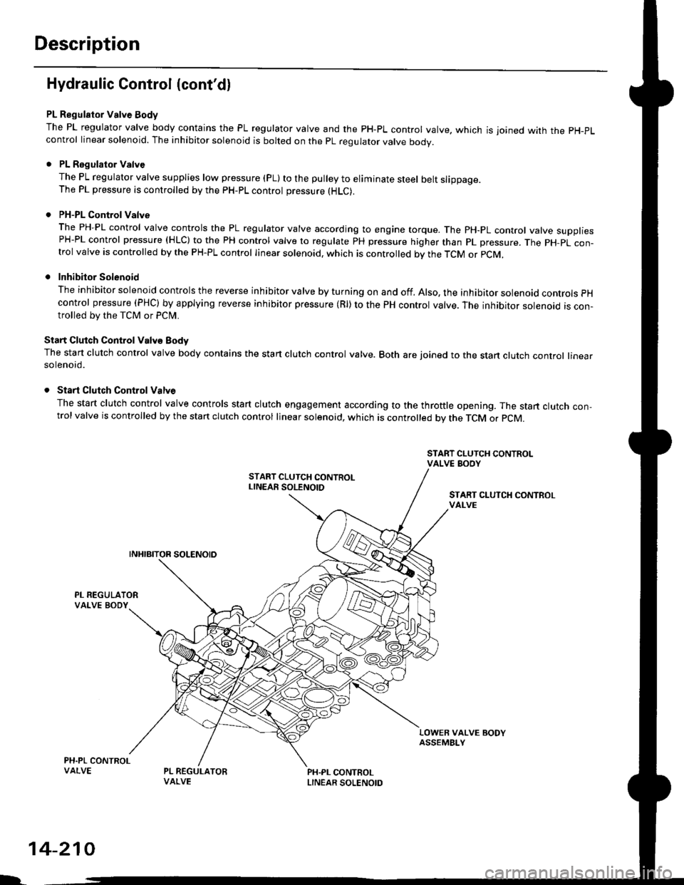
PL Regulator Valve Body
The PL regulator valve body contains the PL regulator valve and the PH-PL control valve. which is joined wirh the pH-pL
control linear solenoid. The inhibitor solenoid is bolted on the pL regulator valve body.
. PL Regulator Valve
The PL regulator valve supplies low p.essure (pL) to the pulley to eliminate steel belt slippage.The PL pressure is controlled by the pH-pL control pressure (HLC).
. PH-PL Control Valve
The PH-PL control valve controls the PL regulator valve according to engine torque. The PH-PL control valve suooliesPH-PL control pressure (HLC) to the PH control valve to regulate PH pressure higher than pL pressure. The pH-pL con-trol valve is controlled by the PH-PL control linear solenoid. which is controlled by the TcM or pcM,
. Inhibitor Solenoid
The inhibitor solenoid controls the reverse inhibitor valve by turning on and off. Also, the inhibitor solenoad controls pH
control pressure (PHC) by applying reverse inhibitor pressure (Rl) to the PH control valve. The inhibitor solenoid is con-trolled by the TCM or Pclvl.
Start Clutch Control Valv€ Body
The start clutch control valve body contains the start clutch control valve. Both are joined to the stan clutch control linearsolenoid.
. Start Clutch Control Valve
The start clutch control valve controls start clutch engagement according to the throttle opening. The start clutch con,trol valve is controlled by the stan clutch control linear solenoid, which is controlled bv the TCM o. pCM.
START CLUTCH CONTROLvAt-vE
LOWER VALVE BODYASSEMBI-Y
PH.PL CONTROLLINEAR SOLENOID
I.
14-210
Page 889 of 2189

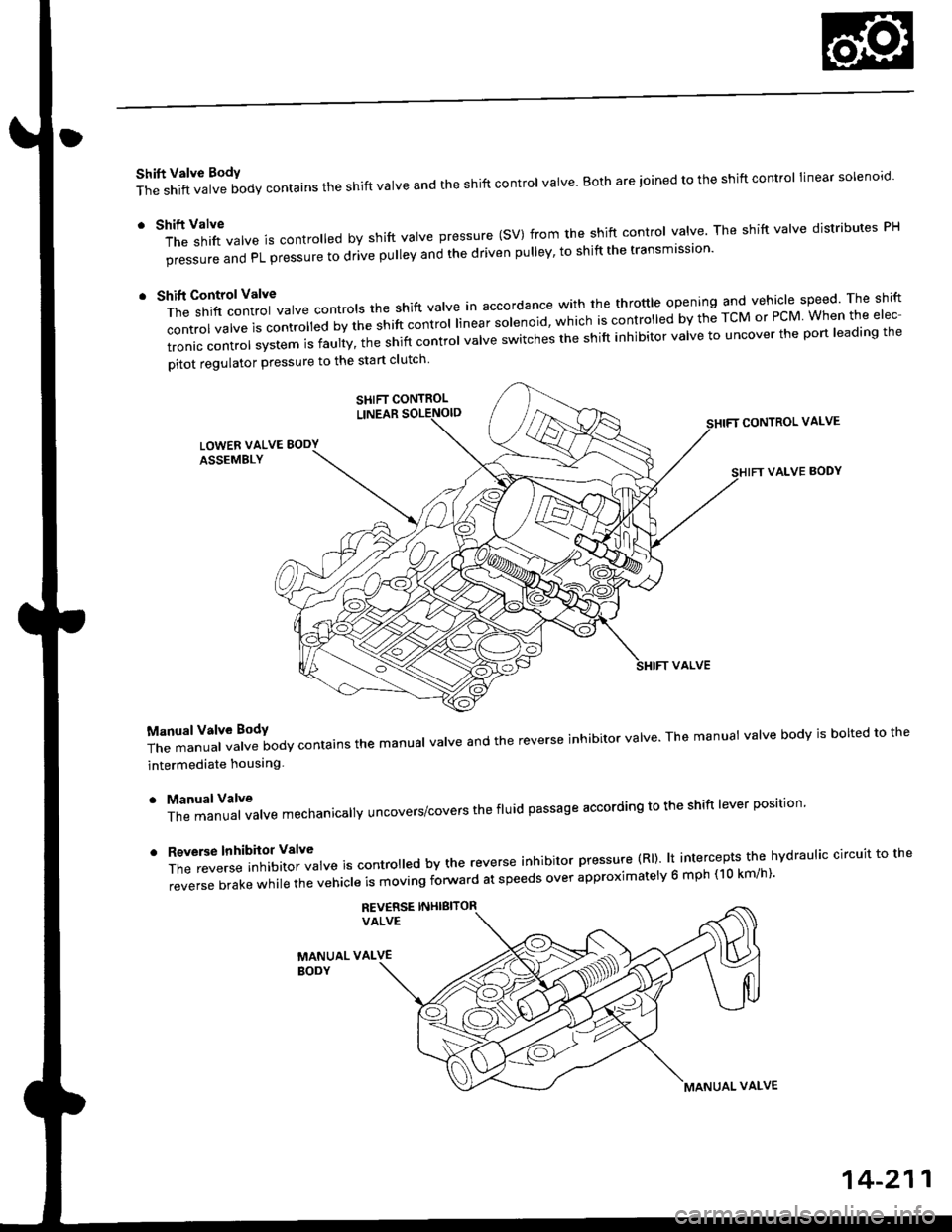
Shift Valve BodY
The shift valve body contains the shift valve and the shift control valve. Both are ioined to the shift control linear solenoro.
r tl'ft1il1rf"","" is controred by shift varve pressure (sV) from the shift contror varve. The shift varve distributes pH
pi""aur" "nO PL pressure to drive pulley and the driven pulley' to shift the transmission'
t t*"rilf:::lr';ivarve contrors the shift varve in accordance with the throttre opening and vehicle speed rhe shift
control valve is convorr"o uv ti" "iirt "ontrol linear solenoid, which is controlled by the TcM or PcM When the elec-
tronic control system is faulty, t;; snift controt uutue "witches the shift inhibitor valve to uncover the port leading the
pitot regulator pressure to the start clutch
CONTROL VALVE
VALVE BODY
T;J:"i"""1ff"t""ilody contains the manuar varve and the reverse inhibitor varve. The manuat varve bodv is borted to the
intermediate houslng
. ManualValve
The manual valve mechanicallY uncovers/covers the fluid passage according to the shift lever position'
'
ff:e;;;.'::'?Xftl::T",* is contro ed by the reverse inhibitor pressure (Rl). lt intercepts the hvdraulic circuit to the
reverse brake while the vehicle is moving forward at speeds over approximatelv 6 mph (10 km/h)'
REV€RSE INHIBITORVALVE
MANUAL VALVEBODY
SHIFT CONTROL
MANUAL VALVE
14-211
Page 890 of 2189
Description
Hydraulic Flow
General Chart of Hydraulic prossure
'Shift Valve. Shift inhibitor Vatve
PH REGULATOR
VALVE
NO.DESCRIPTION OF PRESSURE
CLUTCH CONTROL
ATF COOLER
CLUTCH REDUCING
NO.DESCRIPTION OF PRESSURE
PITOT PIPEccPP
coLPRPITOT REGULATOR
RECIRCULATIONRCC
DNDRIVEN PULLEYRIREVERSE INHIBITOR
REVERSE BRAKE
START CLUTCH
SHIFT II"IHlBITOR
SUCTII'N
SHIFT VALVE
LEAK
DRDRIVE PULLEYRVS
FWDFORWARD CLUTCH
PH-PL CONTROL
sc
HLCsl
LUBLUBBICATION
PRESSURE HIGH
SUC
PH
PHCPH CONTROLX
PLPRESSURE LOW
14-212
Page 891 of 2189
E Position
Astheengineturns.theATFpumpa|sostartstooperate.F|uidfromtheATFpumpf|owstothePHregu|atorva|veandthe
c|Utchreducingva|ve.ThePHregu|atorva|veregu|ateshighpressure(PH).andsendittotheshiftVa|veandthePLregU'
latorvalve.Thehighpressure(PH)flowstothemovablefaceofthedrivenpulleyviatheshiftvalve'andturnsintolow
pressure(PL)atthePLregu|atorva|ve.Thelowpressure(PL}f|owstothemovab|e'aceofthedrivepu||eYviatheshift
valve. At this time, the pulley ratio remarns low'
Thehighpressure(px)uecomesttrectutchreducingpressure(CR)atthec|utchreducingva|Ve.Thec|utchreducingpres.
sure (CR) flows to the start clutch cont'oi uatt". tn"lt"n'al valve' the PH-PL control valve' and the shift control valve' and
is intercepted bY those valves
Under this condition, hydraulac pressure is not applied to the clutches and reverse brake'
(cont'd)
14-213
Page 892 of 2189
Description
Hydraulic Flow (cont'dl
lll position, at low spo€d range
The flow of fluid up to the drive pulley, the driven pulley, and the clutch reducing valve is the same as in El position. Thepulley ratio is low because the driven pulley receives high pressure (PH), and the drive pulley receives low pressure (pL),The clutch reducing pressure {cR) flows through the manual valve to the forwaro clutch, ttren forward ciulcn is engaged.The forward clutch then drives the drive pulley shaft, which drives the d(ven pu ey shaft.Also' clutch reducing pressure {cR) flows to the start clutch control valve, and becomes clutch control pressure {cc).clutch control pressure (cc) becomes start clutch pressure (sc) at the shift inhibitor valve. stan clutch pressure {sc) isapplied to the start clutch to engage the start clutch.
14-214
Page 893 of 2189
E position, at middle sPeed range
Asthespeedofthevehic|ereachestheprescribedVa|ue,theshiftcontro||inearsolenoidisactivatedbytheTcMorPcM'
Theshiftcontro||inearso|enorocontroIsttresniftcontroIVa|vetoactivateshiftVa|vepressure(SV)'c|utchreducingpres-
sure (CR) trom the clutch reduclng valve becomes shift valve pressure (SV) at the shift control valve Shift valve pressure
(SV)flowstothe|eft"noottr'"st'ittu"tue.theshiftVa|Vetotherightsideandpositioningitinthemidd|eofitstrave|.The
shift valve covers th" pon ao ",oo nLior".irr" tiHl a ,tr" pulleys, and uncovers the port leading low pressure (PL) to the
pu eys. The drive pu ey and tne oriJen priLy |."""iu" to* pressure (PL). At this time, the pulley ratio is in the middle'
Pressure remains to apply the forward clutch and the start clutch'
NOTE: When used, "|eft" or "right" indicates direction on the hydraulic circuit'
(cont'd)
14-215