2000 HONDA CIVIC Switch
[x] Cancel search: SwitchPage 874 of 2189

Description
(cont'd)
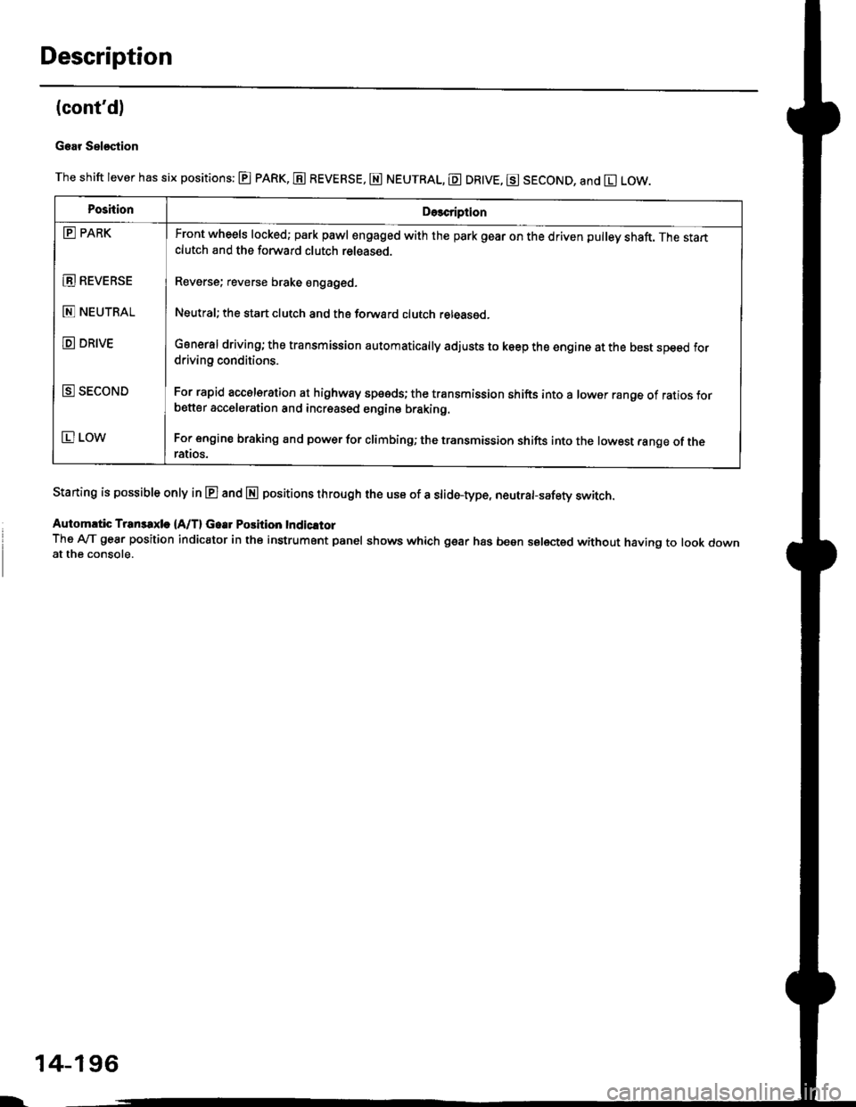
Gear Sel€stion
The shift lever has six positions: @ pARK, E REVERSE, E NEUTRAL, E DR|VE, g SECOND, and El LOW.
Staning is possible only in E and E positions through the use of a slid6-type, neutrafsafety switch.
Automrtic Transaxle {A/T} Gear Position Indicltor
The A-lT gear position indicator in the instrument panel shows which gear has been selected without having to look downat the console.
PoshionDe3cription
E PARK
E REVEBSE
E NEUTRAL
D DRIVE
E SECOND
E LOW
Front wheels locked; park pawl engaged with the park gear on the driven pulley shaft. The startclutch and the forward clutch released.
Reverse; reverse brake engaged.
Neutral; the start clutch and the forward clutch released.
General driving; the transmission automatically adjusts to keep the engine at the best speed fordriving conditions.
For rapid accelsration at highway speeds; the transmission shifts into a lower range of ratios forbetter acceleration and increased engine braking.
For engine braking and power for climbinO; the transmission shifts into the lowest range of theralros.
l-
14-196
Page 876 of 2189

Description
Clutches/Reverse Brake/Planetary Gear/Pulleys
Clulches/Reverse Brake
The CVT uses the hydraulically-actuated clutches and brake to engage or disengage the transmission gears. When
hydraulic pressure is introduced into the clutch drum and the reverse brake piston cavity, the clutch piston and the reverse
brake piston move. This presses the friction djscs and the steel plates together, locking them so they don't slip. Power is
then transmitted through the engaged clutch pack to its hub-mounted gear. and through engaged ring gear to pinion
gears.
Likewise, when the hydraulic pressure is bled from the clutch pack and the reverse brake piston cavity, the piston releases
the friction discs and the steel plates, and they are free to slide past each. This allows the gear to spin independently on its
shaft, transmitting no power.
Start Clutch
The start clutch, which is located at the end of the driven pulley shaft, engages/disengages the secondary drive gear.
The start clutch is supplied hydraulic pressure by its ATF feed pipes within the driven pulley shaft.
Forward Clutch
The forward clutch, which is located at the end of the drive pulley shaft, engages/disengages the sun gear.
The forward clutch is supplied hydraulic pressure by its ATF feed pipe within the drive pulley shaft.
Reverse Brake
The reverse brake, which is located inside the inte.mediate housing around the ring gear, locks the ring gear in E posi-
tion. The reverse brake discs are mounted to the ring gear and the reverse brake plates are mounted to the intermediate
housing. The reverse brake is supplied hydraulic pressure by a circuit connected to the internal hydraulic circuit.
Planetary Gear
The planetary gear consists of a sun gear, a carrier assembly, and a ring gear. The sun gear is connected to the input shaft
with splines. The pinion gears are mounted to the carrier which is mounted to the fo.ward clutch drum. The sun gear
inputs the engine power via the input shaft to the planetary gear, and the carrier outputs the engine power. The ring gear
is only used for switching the rotation direction of the pullev shafts,
In E. E, and E positions (forward range), the pinion gears don't rotate and revolve with the sun gear, so the carrier
rotates. In E] positjon {reverse range), the reverse brake locks the ring gear and the sun gear drives the pinion gears to
rotate. The pinion gears rotate and revolve in the opposite direction from the rotation direction of the sun gear, and the
carrier rotates with pinion gear revolution.
Pulleys
Each pulley consists of a movable face and a fixed face, and the effective pulley .atio changes with engine speed. The
drive pulley and the driven pulley are linked by the steel belt.
To achieve a low pulley ratio, high hydraulic pressure works on the movable face of the driven pulley and reduces the
effective diameter of the drive pulley. and a lower hydraulic pressure works on the movable face of the drive pulley to
eliminate the steel belt slippage. To achieve a high pulley ratio, high hydraulic pressure works on the movable face of the
drive pulley and reduces the eifective diameter of the driven pulley, and a lower hydraulic pressure works on the movable
face of the driven pulley to eliminate the steel belt slippage.
b
14-198
Page 882 of 2189

Description
Electronic Control System ('gG - 98 Modelsl (cont'dl
Circuit Diagram and Terminal Locations
GNITIONSWITCN
Pri - Pt coNTnoLLrN ns0LtN0t0
SIAiT CLUTCH CONTSOLLINEAFSOLENOID
sHtFT CONmOILINIAftSOLENOID
BFAXELIGHT
PAS|(ING 8MI(E SWITCH
i\c-...............- +B
i\--------.--_ rcr
: MAP(PBIg s61
E rtDiRxo
g TM8
scs
123518I1011't22578910
14172023261213t4t6171820
D
14-204
Page 884 of 2189

Description
Electronic Control System ('99 - 00 Modelsl (cont'dl
Grade Logic Control System
How it works:
The PcM compares actual driving conditions with memorized driving conditions. based on the input from the vehiclespeed sensor, the throttle position sensor, the manifold absolute pressure sensor, the engine coolant temperature sensor,the brake switch signal, and the shift lever position signal, to control shifting while the vehicle is ascending or descendinga slope.
Ascending Control
When the PCM determines that the vehicle is climbing a hill in E position, the system selects the most suitable shiftschedule (pulley ratio) according to the magnitude of a gradient. so the vehicle can run smooth and have more powerwhen needed. There are three ascending modes with different shift schedules according to the magnitude ot a gradient inthe PCM.
Descending Control
when the PCM determines that the vehicle is going down a hill in E position. the system selects the most suitable shiftschedule (pulley ratio) according to the magnitude of a gradient. This, in combinstion with engine braking, achievessmooth driving when the vehicle is descending, There are three descending modes with different shift schedules accord-ing to the magnitude of a gradient in the PCM.
L
14-206
Page 887 of 2189

Secondary Valve Body
The secondary valve body contains the PH regulator valve. the clutch reducing valve' the start clutch valve accumulator'
and the shift inhibitor valve
PH Regulator Valve
The pi regulator valve maintains hydraulic pressure supplied from the ATF pump. and supplies PH pressure to the
hvdraulic control circuit and the lubrication circuit. PH pressure is regulated at the PH regulator valve by the PH control
pressure (PHC) from the PH control valve.
Cluteh Reducing Valvo
The clutch reducing valve receives PH pressure from the PH regulator valve and regulates the clutch reducing pressure
(cR). The clutch reducing valve supplies clutch pressure (cR) to the manual valve and the start clutch control valve' and
supplies signal pressure to the PH-PL pressure control valve. the shift control valve, and the inhibitor solenoid valve'
Start Clutch Valv€ Accumulator
The start clutch vatve accumutator stabilizes the hydraulic pressure that is supplied to the start clutch'
Shift Inhibitor Valve
The shift inhibitor valve switches the fluid passage to switch the start clutch control from electronic control to hydraulic
control when the electronic control system is faulty. lt also suppliss clutch reducing pressure (cR) to the pitot regulator
valve and the pitot lubrication pipe.
START CLUTCH VALVE
SECONDARY VALVEBODY
SHIFT INHIBITOE VALVE
(cont'd)
PH REGULATOR VAL
REDUCING VALVE
14-209
Page 901 of 2189

Component Locations
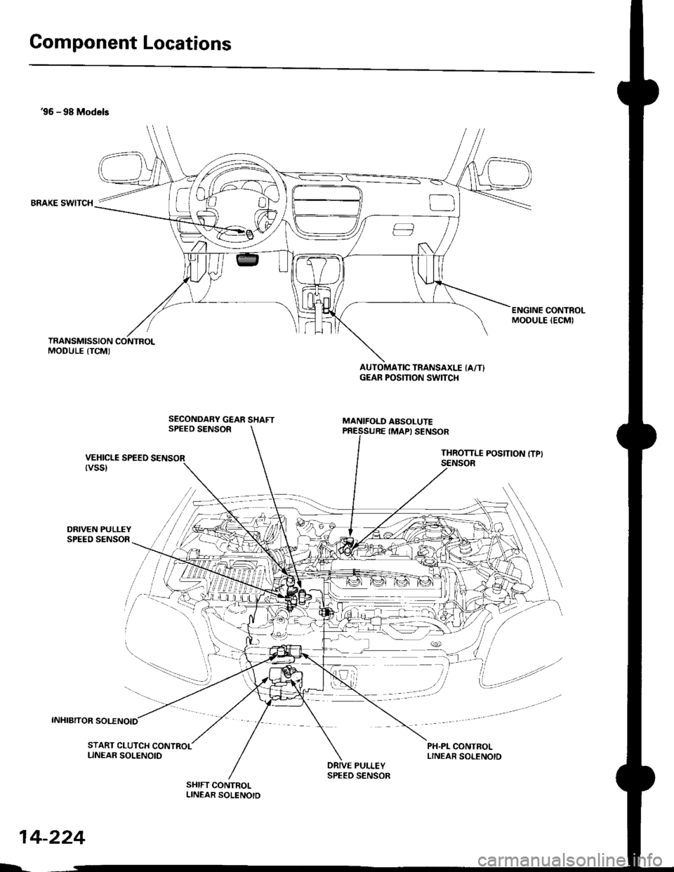
36 - 98 Models
BRAKE SWITCH
DRIVEN PULLEYSPEED SENSOR
INHIBITOR SOLENOID
ENGINE CONTROLMODULE IECMI
SECONDARY GEAR SHAFTSPEEO SENSOR
AUTOMATIC TRANSAXLE (A/T}GEAR POSITION SWITCI{
MANIFOLD ABSOLUTE
VEHICLE SPEEO SENSOR{vss}
IMAPI SENSOR
THROTTI.I POSITION {TPISENSOR
PH.PL CONTROLLINEAR SOLENOID
/i/ i,' / ,','4
,i/:1
t"--.---.- i,,
-_,-:-_a.--:
il
START CLUTCH CONTROLLINEAR SOLENOIDPULLEY
SHIFT CONTROLLINEAR SOLENOTD
$r,
14-224
h
SPEED SENSOR
Page 905 of 2189

TCM Terminal Voltage/Measuring Gonditions
('96 - 98 Modelsl
TCM Terminal Loc.tions
TCM-A l25P) Connecto.
TCM CONNECTOR A (26P}
TCM-B (22P) Connectot
2418910111213
1115161720232526
Terminal NumbetSignalDsscriptionMoasuring Conditions/Torminsl Vohrgo
A1SC LS_Stan clutch control linear solenoidpower supply negative electrodeEngine idling, E position:Approx. 0.4 VHLC LS-PH-PL control linear solenoid Dowersupply negative electrodeEngine idling, E position:Approx. 0.7 V
Shift control linear solenoid oowersupply negative electrodeEngine idling, E position:Approx. 0.8 V
A4LG1Ground
NEEngine speed signal inputWith engine running: Pulsing signalA6Not used
A7ATP LA/f gear position switch El positionsignal inputInEposition:OVIn other than El position: Approx. 1O VA8ATP Sly'T gear position switch E positionsignal inputIn lg position: 0 VIn other than E position: Approx. 10 VA9ATP DA{/T gear position switch E positionsignal inputIn lll position: 0 VIn other than E position: Approx. 10 VAr0ATP NPA,/T gear position switch E or Eposition signals inputInEorEposition:oVIn otherthan E orE position: Approx. 1O VA11ATP RA,/T gear position switch E positionsignal inputIn lE position: 0 VIn other than E position: Approx. 1O VA.12tGlPower supply systemWith ignition switch ON (ll): Banery voltsgeWith ignition switch OFF: 0 VA13PG1Ground
414Start clutch control linea. solenoidpower supply positive electrodeEngine idling, E position:Approx. 2.5 VA15HLC LS+PH-PL control line8|. solenoid powersupply positive electrodeEngine idling, El position:Approx. 5.0 VA16SH LS+Shift control linear solonoid oowersupply positive electrodeEngine idling, E position:Approx. 6.0 V417Ground
A18Not used
A19Not used
420D INDE indicator light controlWhen l9l indicator light comes on: Approx. jO VWhen lll indicator lighr OFF: 0 VA2'lNot used
422Not used
VBUBack-up power systemAlways battery voltage424Not used
A.25tG1Power supply systemWith ignition switch ON (lt): Baftery voltageWith ignition switch OFF:0 VPG1Ground
L
14-228
Page 906 of 2189

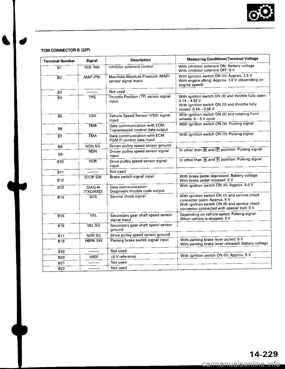
TCM CONNECTOR B (22P}
Terminal NumbelSignalDescriptionMeasuring Conditions/Terminal Voltage
B1SOL INHInhibitor solenoid controlWith inhibitor solenoid ON: Baftery voltage
With inhibitor solenoid OFF: 0 V
82MAP (PB)-M an if old Absol r-rte Pressure IMAP)
sensor signal inPUtWith iqnition switch ON (ll): Approx.2.5 V
With e;gine adling: Approx. 1.0 V (depending on
engine speed)
B3Not used
B4TPS-Throttle Position (TP) sensor signal
input
With ignition switch ON (ll) and throftle fully open:
4.14 - 4.42 VWith ignition switch ON (ll) and throttle fully
closed: 0.44 - 0.56 V
VSSVehicle Speed Sensor (VSS) signal
Inpur
With ignition switch ON (ll) and rotating front
wheelsr 0-5Vcycle
TMBData communication with ECM:
Transmission control data outpUt
With ignilion swltch UN lll): rulslng slgnar
81TMAData communication with EClvl:
PGM Fl control data inPut
With ignition swltch uN {ll,: l-ulslng slgnal
B8NDN SGDriven pulley speed sensor ground
B9NDNDriven pulley speed sensor signal
input
ln other thTnE and E position: Pulsing signal
810NDRDrive pulley speed sensor signal
Input
-tn ottrer ttran E ana E position: Pulsing signal
811Not used
812STOP SWBrake switch signal inPutWith brake pedal depressed: Battery voltage
With brake pedal released: 0 V
813DIAG-H(TXD/RXD)Data communication:Diagnostic trouble code outPut
Wittr ignitio.r s*itct' ON (ll): Approx 5.0 V
814Se-ice ctrect signatWith ignition switch ON (ll) and service check
connector oPen: APProx.5 V
With iqnition switch ON (ll) and service check
"onn"itot. connect"d with special tool: 0 V
Secondary gear shaft speed sensor
signal input
Depending on vehicle speed: Pulsing signal
When vehicle is stoPped: 0 V815VEL
816VEL SGSecondary gear shaft speed sensorgrouno
817NDR SGDrive pulley speed sensor ground
818HBRK SWParking brake switch signal inPutWith parking brake lever pulledr 0 V
With parking brake lever released: Battery voltage
819Not used
B�20VREF+5 V relerenceWith ignition switch ON (ll): Approx 5 V
821Not used
Not used