2000 HONDA CIVIC Section 23
[x] Cancel search: Section 23Page 1734 of 2189
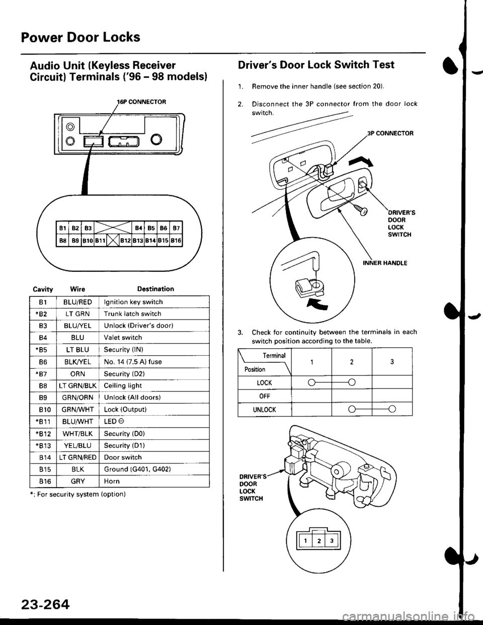
Power Door Locks
Audio Unit lKeyless Receiver
Circuitl Terminals ('96 - 98 modelsl
CavityWireDestination
16P CONNECTOR
B1BLU/REDlgnition key switch
*82LT GRNTrunk latch switch
Ft2BLU/YELUnlock (Driver's door)
B4BLUValet switch
*85LT BLUSecurity {lN)
B6BLK/YE LNo. 14 (7.5 A) fuse
*81ORNSecurity (D2)
B8LT GRN/BLKCeiling light
B9GRN/ORNUnlock (All doors)
810GRNA/VHTLock (OutPutl
*811BLU/WHTLED O
*812WHT/BLKSecurity (D0)
+B 13YEL/BLUSecurity (D'l )
814LT GRN/REDDoor switch
B15BLKG round (G401, G402)
o toGRYnorn
*: For security system (option)
23-264
Driver's Door Lock Switch Test
1. Remove the inner handle (see section 20).
2. Disconnect the 3P connector from the door lock
switch.
Check for continuity between the terminals in each
switch position according to the table.
DRIVER'SDOORLOCKswtTcH
Terminal
Position123
LOCKo-----o
OFF
UNLOCKo----o
Page 1735 of 2189
l
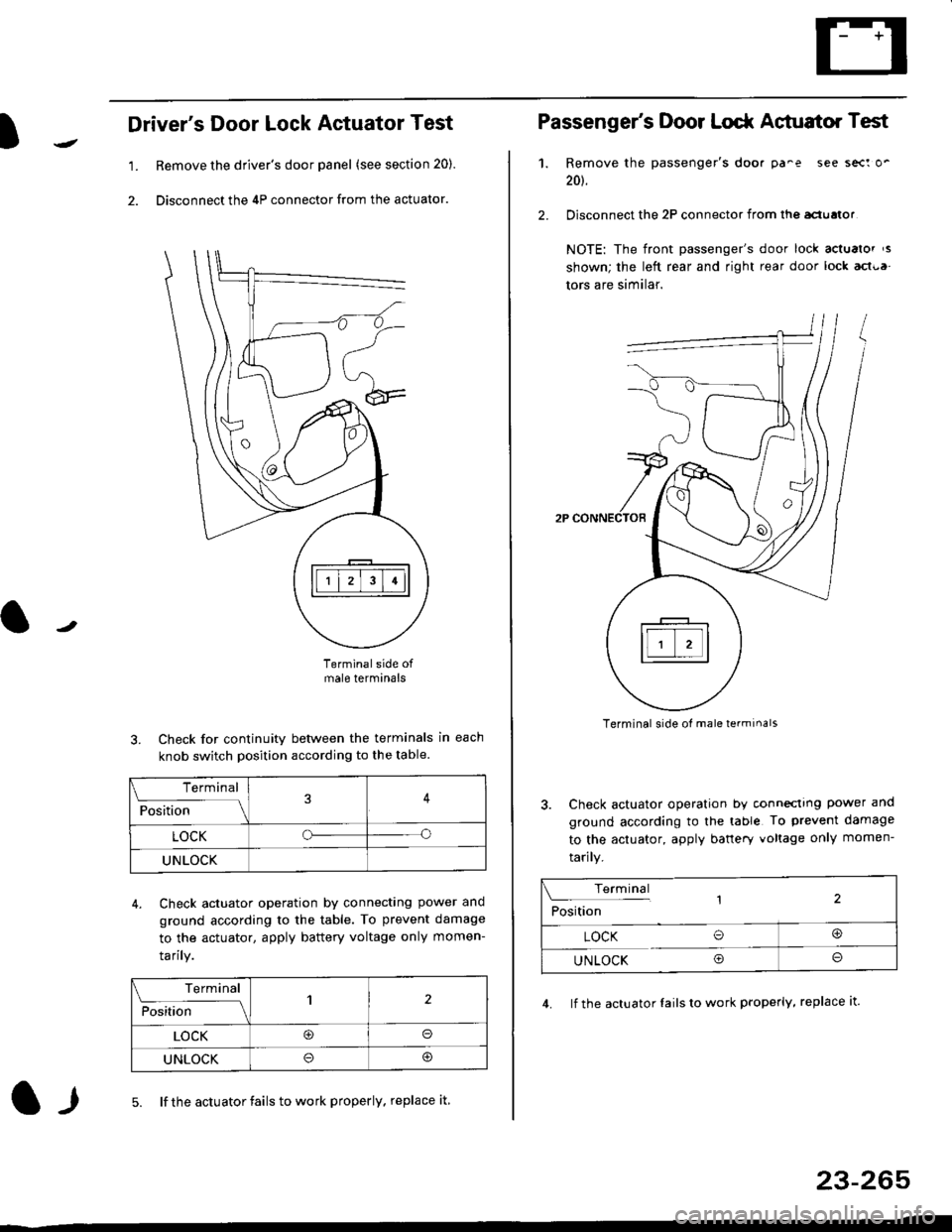
Driver's Door Lock Actuator Test
1. Remove the driver's door panel (see section 20).
2. Disconnect the 4P connector from the actuator.
J
Terminalside ofmale terminals
3. Check for continuity between the terminals in each
knob switch position according to the table.
4. Check actuator operation by connectlng power ano
ground according lo the table. To prevent damage
to the actuator, apply battery voltage only momen-
tarilY.
l-l5. lf the actuator fails to work properly. replace it
23-265
Terminal
F""lti* - lll
LOCKo
UNLOCK
Terminal
Fo"JJ'-lrlon';" -ll1
LOCK@o
UNLOCK
Passenger's Door Lodr Actuator Test
1.
2.
Remove the passenger's doo. pa^e see sect o'
201.
Disconnect the 2P connector from lhq aclualor
NOTE: The front passenger's door lock actualor ,s
shown; the left rear and right rear door lock act{,a
tors are similar.
Terminal side ol male terminals
3. Check actuator operation by conneclrng power and
ground according to the table To prevent damage
to the actuator, apply banery voltage only momen-
tarily.
4. lf the actuator Iails to work properly, replace it.
Terminal,2Position
LOCK O@
UNLOCK Oo
Page 1741 of 2189
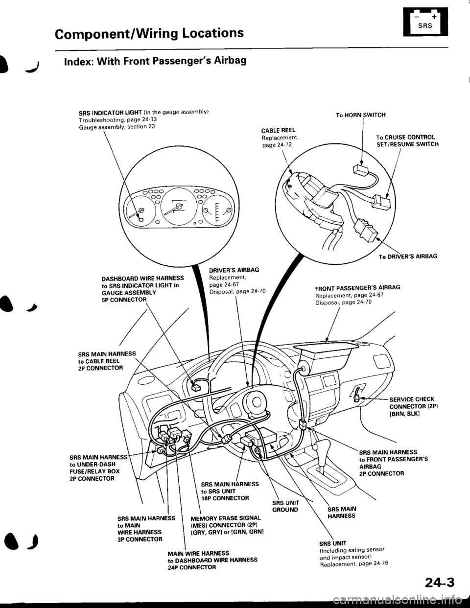
Component/Wiring Locations
)
Index: With Front Passenger's Airbag
SRS INDICATOR LIGHT (ln the gauge assemblvl
Troubleshooting, Page 24 13
Gauge assembly, section 23CABLE REEL
Replacemenlpage 2!-t 2
To HORN SWITCH
SRS UNIT(lncluding safing sensor
and imPact sensorl
Replacement Page 24 76
To DRIVER'S AIRBAG
DASHBOARD WIRE HARNESS
to SRS INDICATOB LIGHT in
GAUGE ASSEMBLY5P CONNECTOB
DBIVER'S AIRBAG
Beplacement,page 24-61Disposal, page 24 70FRONT PASSENGER'S AIBBAG
Replacement, Page 24_67
Disposal, Page 24 70
t
SRS MAIN HARNESSto CABI-E RE€L2P CONNECTOR
SRS MAIN
SERVICE CHECKCONNECTOR {2PI
IBRN, BLK]
to UNOER-OASHFUSE/RELAY BOX2P CONNECTOR
SRS MAIN HARNESSto FRONT PASSENGER'SAIRBAG2P CONNECTOB
SRS MAIN HARNESSto SRS UNITr8P CONNECTOR
SBS MAIN HARNESSto MAINWIRE HARNESS3P CONNECTOR
MEMORY ERASE SIGNAL(MES) CONNECTOR I2P)
[GRY, GRYI or IGRN. GRNI
MAIN WIRE HARNESSto DASHBOARD WIRE HARNESS
24P CONNECTOR
2+3
t,
Page 1742 of 2189
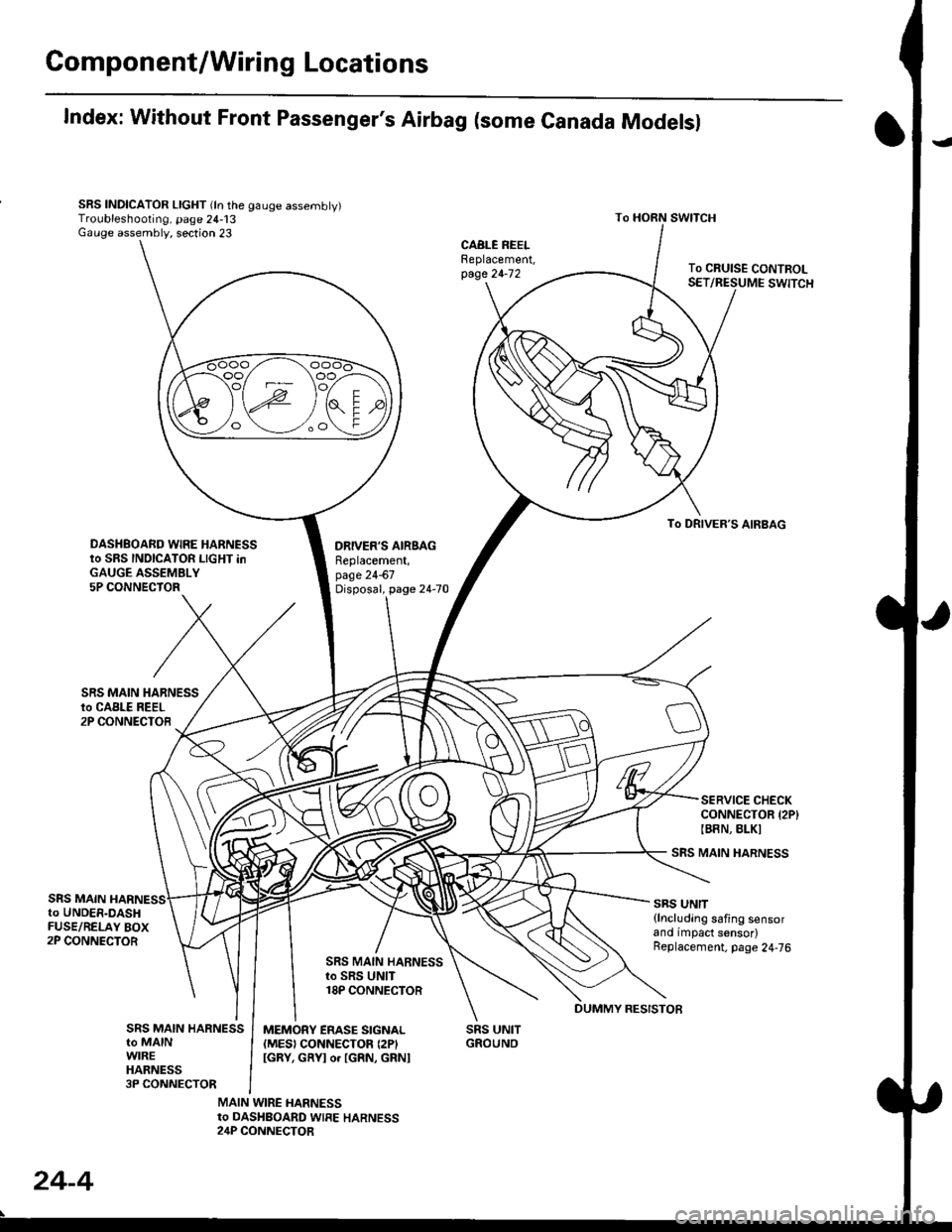
Gomponent/Wiring Locations
Index: Without Front Passenger's Airbag (some Canada Modelsl
SRS INDICATOR LIGHT (ln the gauge assembly)Troubleshooting, page 24-13Gauge assembly, section 23
DRIVER'S AIRSAGReplacement,page 24-67Disposal, page 24-70
SRS UNITGROUNO
To HORN SWITCH
SRS MAIN HARNESS
SRS UNIT{lncluding safing sensorand impact sensor)Replacement. page 24,76
To CRUISE CONTROLSET/RESUME SWITCH
oo/ \oo
To DRIVER,S AIRBAG
DASHBOARD WIRE HARNESSto SRS INDICATOR LIGHT inGAUGE ASSEMBLY5P CONNECTOR
SERVICE CHECKCONNECTOR {2P}IB8N, BLKI
SRS MAINto UNDER-DASHFUSE/RELAY BOX2P CONNECTOR
SRS MAIN HARNESSto SRS UNIT18P CONNECTOR
SRS MAIN HARNESSto MAINWIREHARNESS3P CONNECTOR
MEMORY ERASE SIGNAL(MES) CONNECTON (2P'
IGRY, GRYI o. IGRN, GRNI
MAIN WIRE HARNESSto DASHBOARD WIRE HARNESS24P CONNECTOR
24-4
DUMMY RESISTOB
Page 1745 of 2189
Precautions/ Procedures
)General Precautions
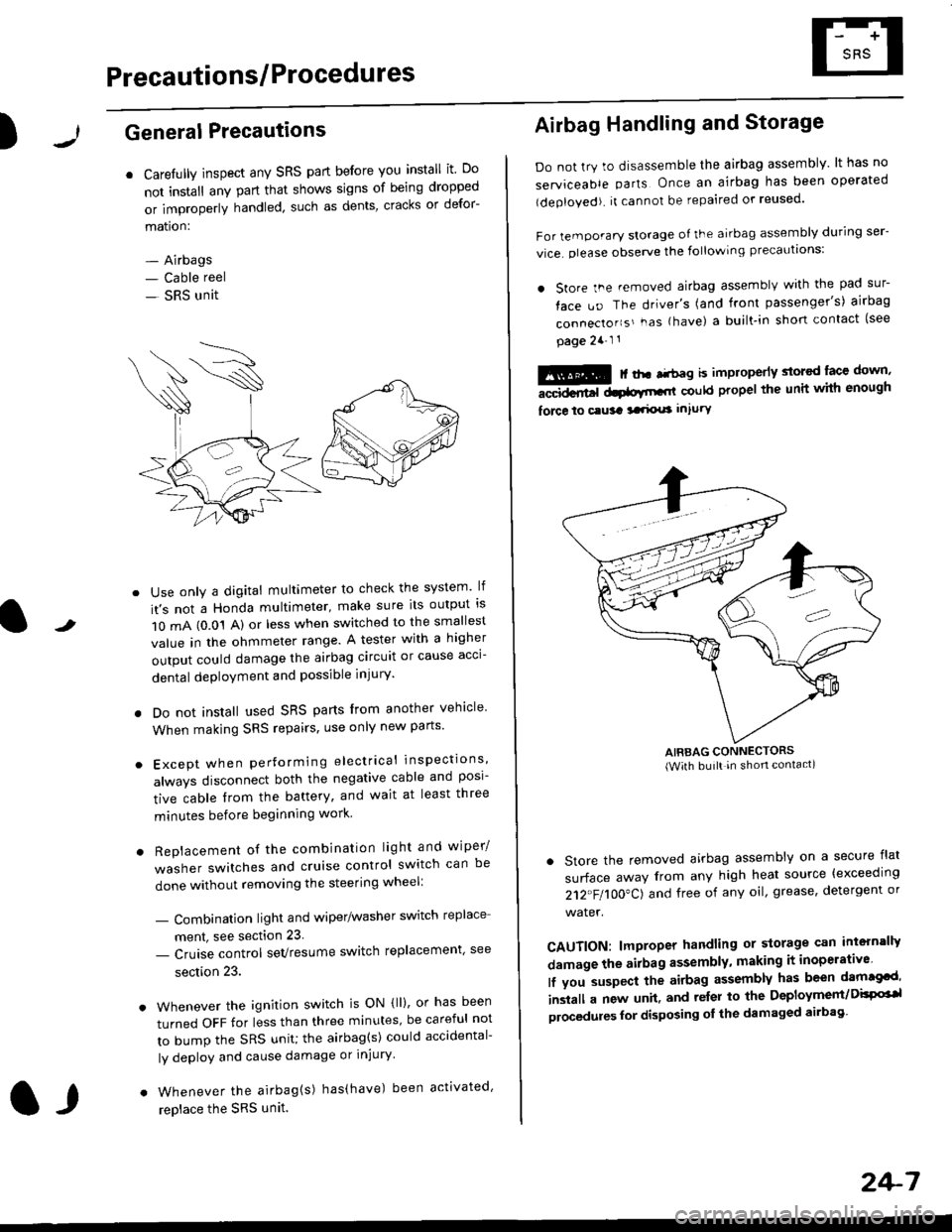
r Carefully inspect any SRS part before you install it Do
not install any part that shows signs of being dropped
or improperly handled' such as dents, cracks or defor-
mation:
- Airbags- Cable reel
- SRS unit
-
Use only a digital multimeter to check the system lf
it's not a Honda multimeter, make sure its output ls
1O mA (0.01 A) or less when switched to the smallest
value in the ohmmeter range. A tester with a higher
output could damage the airbag circuit or cause acci-
dental deployment and possible injury'
I Do not install used SRS parts from another vehicle
When making SRS repairs, use only new pans'
) Except when performing electrical inspections'
always disconnect both the negative cable and posl-
tive cable from the battery, and wait at least three
minutes before beginning work
r Replacement of the combination light and wiper/
washer switches and cruise control switch can be
done without removing the steering wheel:
- Combinalion light and wiper/washer switch replace
ment, see section 23
- Cruise control sevresume switch replacement' see
section 23.
. Whenever the ignition switch is ON {ll), or has been
turned OFF for less than three minutes' be careful not
to bump the SRS unit; the airbag(s) could accidental-
ly deploy and cause damage or injury'
. Whenever the airbag{s) has(have) been activated'
replace the SRS unit.l,
2+7
Airbag Handling and Storage
Do not try to disassemble the airbag assembly. lt has no
serviceable parts Once an airbag has been operated
(deployed). it cannot be repaired or reused'
For temporary storage of the airbag assembly during ser-
vice. olease observe the following precauttons:
. store the .emoved airbag assemblv with the pad sur-
face uo The driver's (and front passenger's) airbag
connecto''s'-as {have) a built.in short contact (see
page 2a-l 1
: | ..r r-+r-a k imninncrlv slorcd lace down,-""dd.r6t dtatltt-,tl could propel the unit whh enough
force lo c.usa 3a.ix! intury
AIRBAG CONNECTORS(With built in shon contact)
. Store the removed airbag assembly on a secure flat
surface away from any high heat source {exceeding
212"FI1OO"CJ and free of any oil' grease, detergent or
water.
CAUTION: lmproper handling or storage can intern'lJy
damage the airbag assembly, making it inoperativo
lf you suspect the airbag assembly has been dam€cd'
inslall a new unit. and relsr lo the Deployment/DisPG'l
olocedules for disposing ol the damaged airbag
Page 1751 of 2189
rl
Troubleshooting
t)
Self-diagnostic Procedures
The self-diagnostic function of the SRS system allows it to locate the causes of system problems and to store this informa' I
tion in memory. For easier troubleshooting, this data can be retrieved via a data link circuit l
. When you turn the ignition switch ON (ll), the SRS indicator will come on. ll it goes off after six seconds. the system is
norma l.
. lf there is an abnormality, the system locates and defines the problem, stores this information in memory, and turns
the sRS indicator light on. The data will remain in the memory even when the ignition switch is turned off or if the bat-
tery is disconnected.
o when you connect the scs service connector to the service check connector (2P), and turn the ignition switch oN (ll),
thesRsindicator|ightwi||indicatethediagnostictroub|ecode(DTC)bythenumberofb|inks.
. After reading and recording the DTC. proceed with the troubleshooting for this code'
Precauiions
.Useon|yadigita|mU|timetertocheckthesystem'|fit,snotaHondamu|timeter,makesureitsoutputisl0mA(0.01A)
or|esswhenSwitchedtothesma||estva|ueintheohmmeterrange,AtesterwithahigheroUtpUtcoulddamagethe��
airbag circuit or cause accidental airbag deployment and possible injury'
r when-ever the ignition switch is oN (ll). or has been turned oFF for lessthan three minutes, be careful nottobumpthe
SRS unit; the airbags could accidentally deploy and cause damage or injuries
. Before you ,"n1ou" th" SRS main harness, disconnect the driver's airbag connector (and the front passenger's airbag
connector).
. Make sure the battery is sufficiently charged {see section 23}. lf the battery is dead or low, measuring valLles won t be
correct.
. Do not touch a tester probe to the terminals in the sRS unit or harness connectors, and do not connect the terminals
with a jumper wire. Use only the backprobe set or the special tools'
For backprobing spring-loaded lock type connectors, refer to page 24-9'
Reading the DTC
when the SRS indicator light is on, read the DTC using one of these methods:
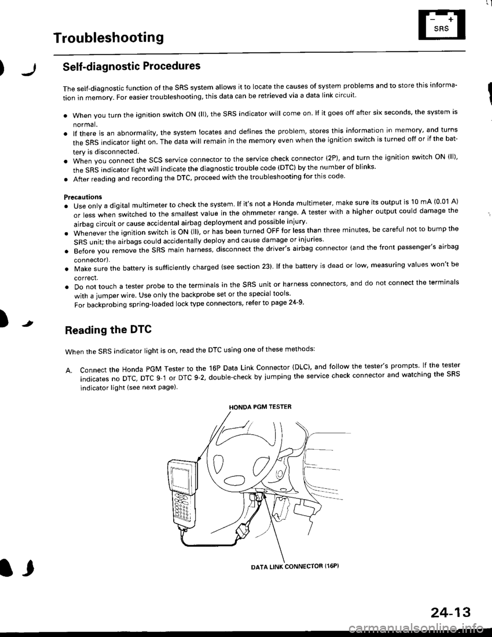
A. Connect the Honda PGM Tester to the 16P Data Link Connector {DLC), and follow the tester's prompts lf the tester
indicatesnoDTc,DTcg-1orDTc9-2,doub|e-checkbyjumpingtheservicecheckconnectorandwatchingthesRS
indicator light (see next Page)
HONDA PGM TESTER
DATA LINK CONNECTOR Il6PI
l,
24-13
Page 1820 of 2189
Power Distribution Schematics
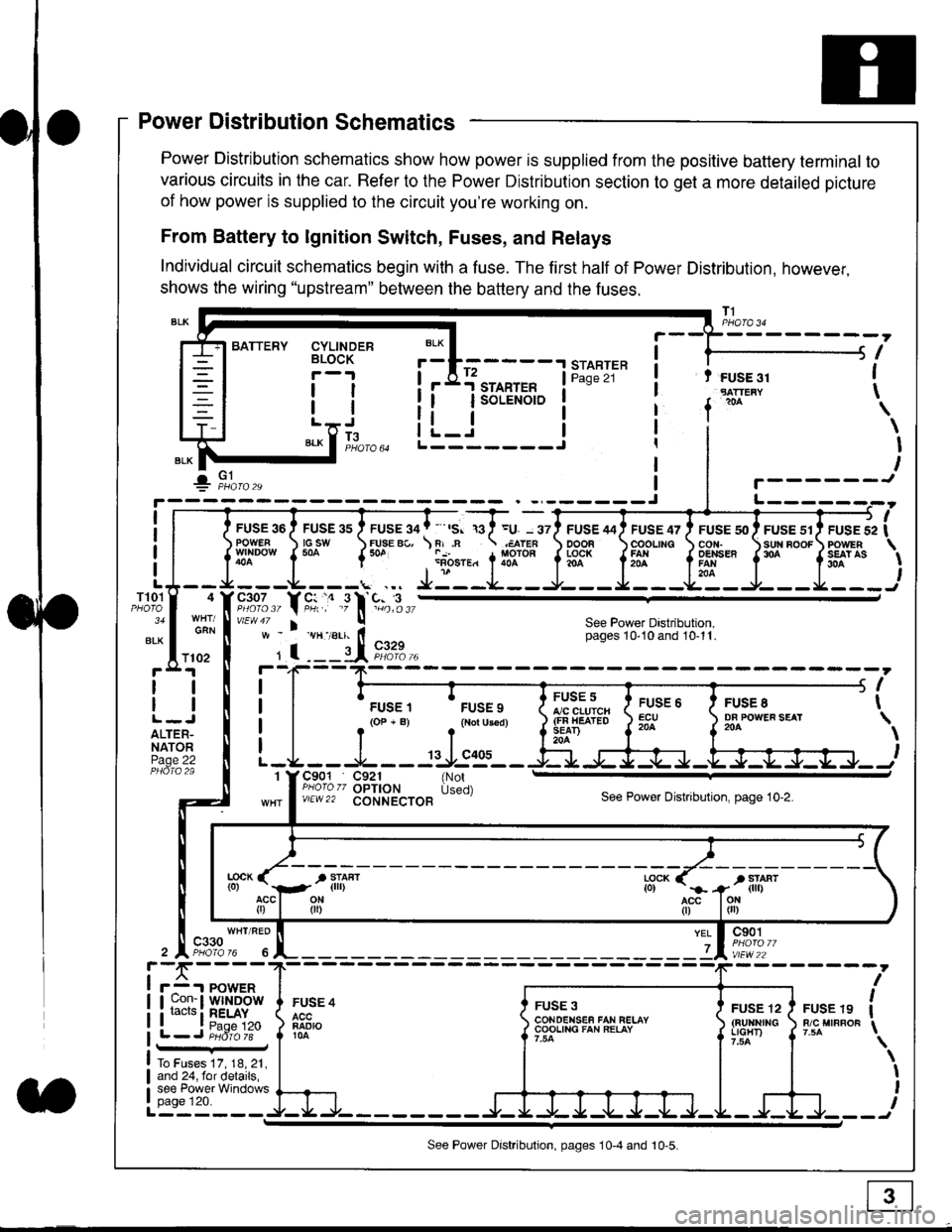
Power Distribution schematics show how power is supplied from the positive battery terminal to
various circuits in the car. Refer to the Power Distribution section to get a more detailed picture
of how power is supplied to the circuit you're working on.
From Battery to lgnition Switch, Fuses, and Relays
Individual circuit schematics begin with a fuse. The first half of Power Distribution, however,
shows the wiring "upstream" between the battery and the fuses.
CYLINDERBLOCK
tl
tlL.lt J
",-* f ]fo,o
i BATTERY
IIII
-
----------------Y-?-
ruse so I ruse as I ruse ga | ' ,s. ,a I =u. - srl ruse aai ruse qr I ruse so I ruse sr i ruse iapowEF csw FUsE Bc, \F,.n .;,cren ooon \coounc cor,r. \sun noor powrnw'NDowf50a {* .i1-;.*"1liT""fi3f* f5# fffi'*"f'* fS?'*
- - -L - - -. ... Ji - -.J.- - - -e- - -l. - - -La - J- - - I - - -
"";%,, Y rtr,' .9 l' -%,t",,vtEw47 I ! See Power Dastribution,w - vH-,alr. lt - pages 10,10and 10-11.
' I ---il 9,1?-l--4F--?-
i I
t.urr, 'rrr.,
t i!?'.,,?"" t::=. l ty::.1----.-
-
i
a I r(op-B) .{Noru3€d) J$ifl#ii Jtocl }3fo**."".o'
t -L - - -L - - -: rJ:e'- - -Ei s+s-r -.Fl-J-Jrr.-.
It-STARTER | !Pase 21 ! t FUSE 31I "rn*i
I f
*
i.Jr;-t
i L_i***'" iL-------J
ilr------!
FUSE /I4 ' FUSE 47 ' FUSE 5{' ' FUSE 51' FUSE 52
rlr
OOOB \COOLING CON. \SUN BOOF FOWER
t3f* f5# fffi*" f'* fs?'*
See Power Dastribution,pages 10'10 and 10-11.
T101
34
ALK
4
GAN
I
I
I
I
I\
\I
I
I
FUSE 8DF POWEF SEAT204
FUSE 6ECU204
FUSE 5A/C CLUICH(FN HEATEDSEAD204
C901 C921 {NotPHoro zz OPTION Used)v/EW22 CONNECTOBSee Power Distnbution, page 10-2.
1
FUSE 4
FADIO104
c901
vlEw22
FUSE 12(BUltNrrGLIGHT)
FUSE 19R/C MIRROF
YEL
7
i-f,r-- 't PowERI uon- I Wlt{DOWi racrs i RELAY. t P^da 1tL-J P;dr1ii-
FUSE 3CONOENSEF FAN RELAYCOOLING FAN RELAY
To Fuses 17, 18, 21,and 24, for details,see Power Windowspage 120.a
ll
ll
ALTER-NATORPage 22
f102
c330
See Power Distribution, pages 10-4 and 10-5.
Page 1823 of 2189
How To Use This Manual
Component Locations
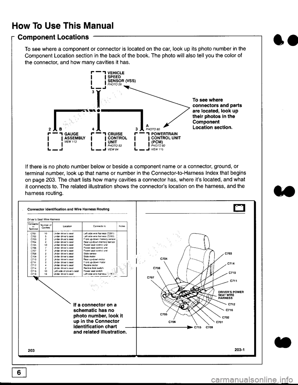
To see where a component or connector is located on the car, look up its photo number in the
Component Location section in the back of the book. The photo will also tell you the color of
the connector, and how many cavities it has.
To see where
connectors and parts
are located, look up
their photos in the
Component
Location section.
I
I
3
r - 1 GAUGE
| | I_S-9_EIBLY
lt''""'
r - 1 cRUtsE
! !fi':*
r - 1 POWERTRAIN
I I CONTROL UNrr
a i[i9#r,
lf there is no photo number below or beside a component name or a connector, ground, or
terminal number, look up that name or number in the Connector-to-Harness Index that begins
on page 203. The chart lists how many cavities a connector has, where it's located, and what
it connects to. The related illustration shows the connector's location on the harness, and the
harness routing.
Connactor ldontlticallon and Wke Harness Rouling
DFIVEF'S POWERSEAT WIAEHAFNESS
It a connector on a
schematic has no
photo number, look it
up in the Connector
ldentilication chart
c712
c7t6
c702c701
and related illustration.
203203.1
Drlvor s Sea! wne Harn€ss
Lefts'd.Hrc hatu$ 1c2611Loft s'd. src hamass 1c262)
F6ar up.dow^ n.morykisor
l
E
oo