Page 1683 of 2189
7.
8.
6. Remove the two screws, cut the wire harness, and
remove the actuator.
Record the terminal locations and wire colors'
Route the wire harness of the new actuator through
the hole in the bracket. Be sure to pass the wlre
under the bracket cliP.
BRACKET
9. Pass the connector boot over the wire harness
23-213
BLK/WHTi
,t
L,
.;{
I
oa
LT GRN I GRY
PNK
10, lnsert the terminals into the connector in the origi-
nal arrangement (recorded in step 7), as shown
Detow.
Right:
SLK/WHT*
BLU/REO'
": Canada '99 - 00 models
Apply tape to seal the intersection of the connector
boot and the wire harness.
Reassemble in the reverse order of disassembly Be
careful not to break the mirror when reinstalling it
to the actuator.
Reinstall the mirror assembly to the door.
Operate the power mirror to check that the actuator
works smoothlY.
Left:
11.
12.
13.
't 4.
PNK
Page 1684 of 2189
Wipers/Washers
Component Location Index
SBS components are located in this area, Review the SRS component locations, precautions, and procedures in the SRSsection (241 betore performing repairs or service.
WIPER/WASHER SWITCHTest, page 23-215REAR WINDOW WIPERMOTOR lHatchback)Test, page 23'216WINDSHIELD WIPER ARMS/BLADES
WINDSHIELD WIPER MOTORTest, page 23-215
WASHER FLUIDRESERVOIR
WASHER MOTOR {Hatchback)Test, page 23'216
INTERMITTENT WIPER RELAYCIRCUIT (ln the integratedcontrol unit)
t_l
Iilr
i
T
23-214
Page 1687 of 2189

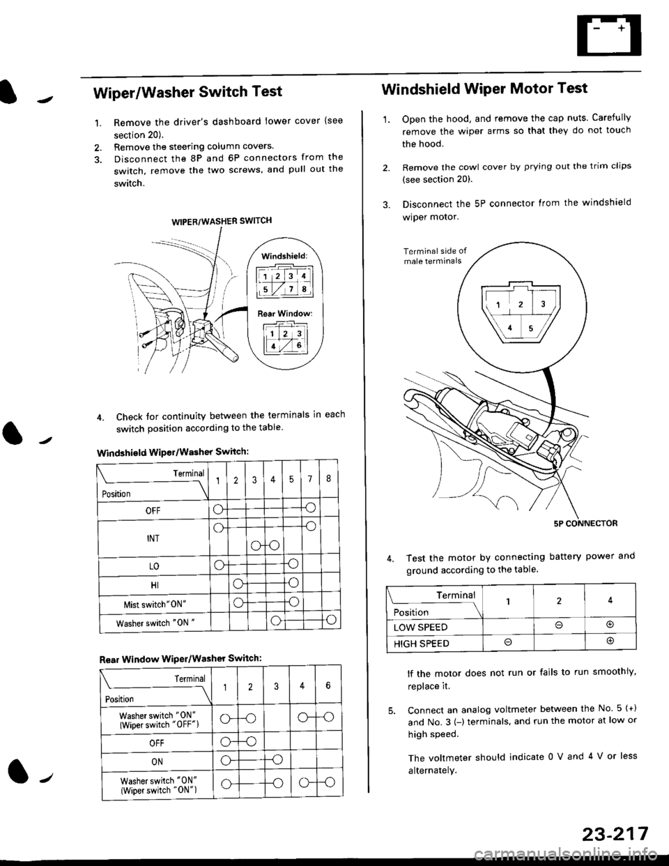
Wiper/Washer Switch Test
Remove the driver's dashboard lower cover {see
section 20).
Remove the steering column covers.
Disconnect the 8P and 6P connectors from the
switch, remove the two screws, and pull out the
switch.
4. Check tor continuity between the terminals in each
switch position according to the table
Windshield Wiper/Washer Switch:
Terminal
Position \
12357I
OFFoo
INTo-o
oo
LOoo
HIoo
l\4ist switch"0N"oo
Washer switch "0N "oo
Rear Window WiPer/Washer Switch:
I Terminal
'i"*
--J2346
Washer switch "0N"
(Wiper switch "OFF"lo--oo--o
OFFo--o
ONo--o
Washer switch "0N"
{Wiper switch "0N")o--oo--o
1.
WIPER/WASHER SWITCH
Windshield:
l1 2 314 |
li.l7a,lil
Rear Window:
11 z 3l
lT-,rtl
Windshield Wiper Motor Test
1.Open the hood, and remove the cap nuts. Carefully
remove the wiper arms so that they do not touch
the hood.
Remove the cowl cover by prying out the trim clips
(see section 20).
Disconnect the 5P connector lrom the windshield
wiper motor.
Test the motor by connecting battery power
ground according to the table.
lf the motor does not run or fails to run smoothiy,
replace it.
5. Connect an analog voltmeter between the No. 5 {+)
and No.3 {-) terminals. and run the motor at low or
high speed.
The voltmeter should indicate 0 V and 4 V or less
alternately.
Terminal
i**l*-
-_\14
LOW SPEEDo@
HIGH SPEEDo@
23-217
Page 1688 of 2189

Wipers/Washers
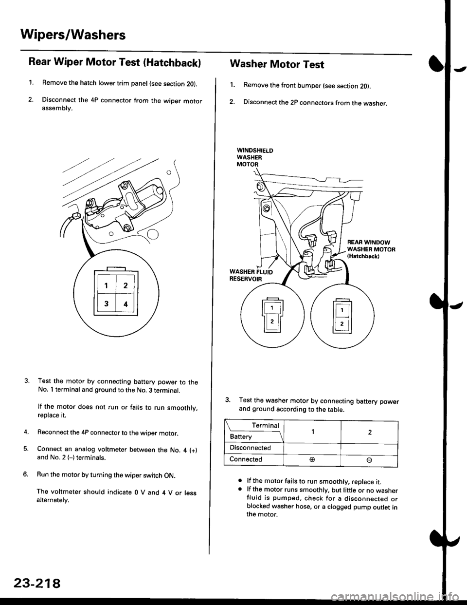
Rear Wiper Motor Test (Hatchback)
1.Remove the hatch lower trim panel (see section 20).
Disconnect the 4P connector from the wiper motorassemDry,
Test the motor by connecting battery power to theNo. 1 terminal and ground to the No. 3 terminal.
lf the motor does not run or fails to run smoothly,reptace rI.
Reconnect the 4P connector to the wiper motor.
Connect an analog voltmeter between the No. 4 (+)
and No.2 (-)terminals,
Run the motor by turning the wiper switch ON.
The voltmeter should indicate 0 V and 4 V or lessalternately.
23-218
1.
Washer Motor Test
Remove the front bumper (see section 20).
Disconnect the 2P connectors from the washer,
a
a
lf the motor fails to run smoothly, replace it.lf the motor runs smoothly. but little or no wasnerfluid is pumped. check for a disconnecr€o orblocked washer hose, or a clogged pump outlet inthe motor.
REAR WINDOWWASHER MOTOR(Hatchbackl
WASHER FLUIORESERVOIR
3. Test the washer motor by connecting battery power
and ground according to the table.
L f:,ry1Battery1
Disconnected
Connected@
Page 1689 of 2189
Washer LevelSwitch Test (Canadal
1. Remove the front bumper {see section 20)
2. Disconnect the 2P connectors from the washer.
WASHER FLUIORESERVOIRWASHER LEVEL SWITCH
3. Check for continuity between the terminals in each
float position according to the table.
Terminal
;r"l,'t"--l
12
FLOAT UP
FLOAT DOWNoo
23-219
Page 1702 of 2189
Power Windows
Passenger's Window Switch Test
Coupo/H8tchback:
1. Remove the armrest pocket from the door panel
{see section 20}.
5P CONNECTOR
2. Disconnect the 5P connector from th€ passenger's
window switch.
Sodan:
1. Remove the armrest (see section 20).
Disconnect the 5P connector, then .emove the mount-
ing screw from the passenge/s switch.
PASSENGER'S WINDOW SWITCH
5P CONNECTOR
23-232
Switch sids of 5P t.rminal:
Terminal side olmale terminals
Check for continuity between the terminals in each
switch position according to the table.
12a5
Terminal
il;--lI25
UP
-o
-o
OFF
-o
o--o
DOWNo--o
Page 1703 of 2189
Driver's Window Motor Test
Motor Test:
l. Remove the driver's door panel (see section 20).
Terminal side of male terminals
Disconnect the 4P connector from the motor.
Test the motor in each direction by connecting bat-
tery power and ground according to the table.
CAUTION: When th€ molor stops running, discon-
n€ct one lead immediat€ly.
4. lf the motor does not run or fails to run smoothlv.
reDlace it.
3.
l.,,
Terminal
;."t1."
-_l\1
UPo@
DOWNoo
Puls€r Test:
5. Connect the test leads of an analog ohmmeter to the
No. 3 and No. 4 terminals.
6. Run the motor by connecting power and ground to
the No. 1 and No.2 terminals. The ohmmeter needle
should move back and forth alternately.
23-233
Page 1704 of 2189
Power Windows
Passenger's Window Motor Test
Front:
1. Remove the passenger's door panel (see section
20t.
2. Disconnect the 2P connsctor from the window
moIor.
2P CONNECTOR
\
Terminal side ot msleterminals
3. Check window motor operation by connecting power
and ground according to the table.
CAUTION: When the motor stops running. dbcon-
nest ono load immadiatoly.
4. lf the motor doas not run or fails to run smoothly.
replace it.
Terminal
;;,r";--lI
UP@o
DOWN@
23-234
Re!r:
1. Remove the passenger's door panel {see section
20).
2. Disconnect the 2P connectof from the window
motor.
NOTE: The illustration shows the right rear window
motor; the left rear window motor is symmetrical.
2P CONNECTOR
3. Check window motor operation by connecting power
and ground according to the table.
GAUTION: Whon the motor ctops running, discon-
nact one lead immodiatoly.
4. lJ the moto. does not run or fails to run smoothly.
rcDlace it,
Terminal
DI;t;;---l
UPo@
DOWN@