Page 1323 of 2189
Exterior
Component Location Index
NOTE: Refer to the Civic BodV Repair Manual, '1996 Model Series, P/N.6150330,forthe hood, trunk lid and hatch removal.
2Dl30llDl
LICENSE PLATETRIM TRUNK LIDROOF MOLOINGReplacement,
SIDE WINDOWMOLDINGSReplacement,page 20-102Replacement,page 20-100Adjustment, page 20-97Tolsion Bar Removal,page 20-10220 99
HOODAdiustment, page 20 96Hood Edge protector
Replacement, page 20 99
TRUNK LIDWEATHERSTRIPReplacement,page 20-100
REAR BUMPERReplacement,page 2O-95
SILL PANELReplacement, page 20 105
REAR AIR OUTLETReplacement,page 20-106
FUEL PIPEPROTEfiORReplacement,page 20-106
FENDERWELL TRIMReplacement, page 20-106
Replacement,page 20-106
3D:
HATCH
HATCHAdjustment,page 20-98
WEATHERSTRIP
20-93
Page 1328 of 2189
Hatch
Adjustment
NOTE:
. Before adjusting the hatch, loosen each bolt and nut slightly.
a The suDport struts should be removed.
. To adjust, remove both hatch sidetrim (see page 20-63) and the rear roof trim (see page 20-65).
1. Adjust the hatch hinges right and left, as well as fore and aft. by using the elongated holes
2. Turn the hatch edge cushions, as necessary, to make the hatch fit flush with the body at each side.
3. Adjust the hatch fit to the hatch opening by moving the striker.
4. After adiustment, tighten each bolt and nut securely.
6x1.0mm9.8 N.m (1.0 kgf.m,
HATCHEDGE CUSHION
HATCHHINGERearward
HAEDGECUSHION
j ... 22
\,_1q
N.m (2.2 kgf.m,tbf.ftl
\
co
38Nm(3.9kgfm,2.8 rbf.ft)
NOTE: Move the striker right or left until it's centered in
the hatch latch. as shown.
HATCHHINGESTRIKER
l0x1VER
HATCHEDGECUSHION
9.8 N.m 11.0 kst.m,7.2 tbf.ft)HATCHLATCH
20-98
6x1.0mm
Page 1332 of 2189
Side Window MoldingsRoof Molding
Replacement
CAUTION: Put on glovos to protect your hands.
NOTE:
. Take care not to scratch the body
. Remove the screw, and pull th€ side window molding
by hand.
>: Clip locationsA>,13
Installation is the reverse of the removal procedure.
NOTE: lf necessary, replace any damaged clips.
1l
)
A
>: Screw locations,
*@
MOLOING
\
20-102
Replacement
CAUTION: When prying with a flat-tip screwdriver, wrap
it with protestive taps to prevent damage, and use pro-
toctiv€ tape on the body.
NOTE: Take care not to scratch the bodv.
WINDSHIELOMOLDING
Installation is the reverse of the removal procedure.
NOTE:
. Take care not to damage the windshield molding.. Make sure the roof molding is installed securely.
K
PINlBody side)
I
)
Page 1346 of 2189

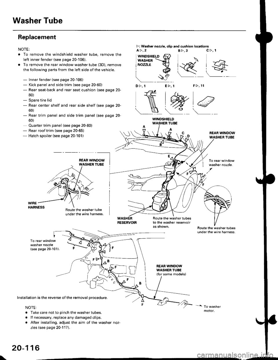
Washer Tube
Replacement
NOTE:
. To remove the windshield washer tube, remove the
left inner fender (see page 20-106),
. To remove the rear window washer tube {3D), remove
the following parts from the left side of the vehicle.
- Inner fender (see page 20-106)- Kick panel and side trim (see page 20-60)- Rear seat-back and rear seat cushion (see page 20-
80)- Spare tire lid- Rear center shelf and rear side shelf (see page 20-
60)- Rear trim panel and side trim panel
60)
Ouarter trim panel (see page 20-60)- Rear roof trim {see page 20-65)- Hatch spoiler (see page 20-101)
(see page 20
WIREHARNESS
>: W.sher nozzle, clip and cushion locationsa>,2B>,3
"J>)
[q@"
F>, 11
c>, 1
wttrtosnteLo 6}usxea =-d
lNozzrE cv
iq
!$e
D>,1 E>, 1
NtW)€
Roote the washer tubeunder the wire harness.
TUBE
A
Route the washer tubesto the washer reservoir
REAB WINDOWWASHER TUBE(Ior some models)
REAR WINDOWWASHER TUBE
washer nozzle.
washer nozzle(see page 20-101).
oo\
Installation is the reverse of the removal procedure.
NOTE:
. Take care not to pinch the washer tubes.
. lf necessary, replace any damaged clips.
. After installing, adjust the aim of the washer noz-
zles (see page 20-117).
20-116
WINDSHIELD
\,--
Page 1359 of 2189
Washer Tube
Replacement (cont'dl
NOTE: To remove the rear window washer tube (3D), remove the following parts from the left side of the vehicle.
- Inner fender (see page 20-'106)- Kick panel and side trim (see page 20-60)- Rear seat-back and rear seat cushion (see page 20-80)- Spare tire lid- Rear center shelf and rear side shelf (see page 20-60)- Rear trim panel and side trim panel (see page 20-60)- Ouarter trim panel (see page 20-60)- Rear roof trim (see page 20-65)- Hatch spoiler (see page 20-1011
>: Washer nozzle, clip and cushion locationsA >.9 B>,2 C>, 1
I sl -..._, 1
aj\
_ ____/ _>_t _ _/
(see page 20 101).
REAR WINDOWWASHER TUBE(for some models)
Installation is the reverse ofthe removal procedure.
NOTE:
. Take care not to pinch the washer tubes.
. lf necessary, replace any damaged clips.
. After installing, adjustthe aim ofthe washer nozzles (see page2O-1111.
motor.
20-130
Page 1471 of 2189

l'f .
Electrical
Special Toofs .,....................,23-2
Troubleshooting
Tips and Precautions ..............,.................... . 23-3
Five-step Troubleshooting .............. ......... . . 23-5
wire color codes ..........,23-5
Schematic Symbols ........,................... . . .. .... 23-6
Relay and Control Unit Locations
Engine Compartment ...,..................... ... .. . 23'7
Dashboard ......................23-8
Dashboard/Door ......... 23-12*Airbags ................. ....... Section 24
Air Conditioning ......... Section 21
Aftelnator ..........."""" """ 23-112
Anti-lock Brake System {ABS) Section 19*A/T Gear Position Indicator .....................,. .... ... 23-149
Automatic Transmission Svstem .... . ....... Section 14
Batterv ......... . . . ... ...... .......23-91
Blower controls .. . ... Section 2l
Charging System ....'...........23'112
Connector ldentilication and Wire Harness
Routing .................. ......23'13
Cruise Control ............,........23-240
Dash Lights Brightness Controller ............. ....... 23-180
Fan controfs "" 23'126
Fuel PumD ........ . ........ section 11
Fuses/Refay ...............,..,,.. 23'62
PGM-FI Control System ......................,....... Section 1 1
*Gauges
Circuit Diagram ....,.,.......23-131
Fuef Gauge ...........'.'.......23-142
Gauge/lndicator .. . .. 23-129
Ground Distribution .. . 23-75
Heatei controls .. . ..... Section 21*Horn................. ...............23-196
*tgnition Switch ....................23-89
lgnition System .......,.... 23-102
*lntegrated Control Unit ....................................... 23-156
fnterlock System ,........ . . , ,23-144
Lighting System . . . .. ......... 23-161
Lights, Exterior
Back-up Lights ..'............23'171
Brake Lights .................. 23'174
Daytime Bunning Lights (Canadal ............... 23'166
Front Parking Lights ......,................ .'. .......... 23-167
Front Turn Signal Lights .......... . . ............ ..,.23-167
Headtights ....".'....-... ..... 23'167
High Mount Brake Light ...................... ... .23'179
License Plate Lights ...... 23'176
Taitfights ................ .......23'171
lnterior Lights ..-.......,, . 23-142
Moonroof ..,.................,........ 23-235
Power Distribution ....... . . .23-61
Power Door Locks .......,,,. .23'251
Power Mirrors ,..............,.,...23'206
Power Relays ....... . ...... . . .. 23-86
Power Windows ............,,....23-220
Rear Window Defogger .......................... . . ... . . 23-2OO
Spark Plugs . ..... . ........ .....23-111
Slarting System ................23-93*stereo Sound Svstem ,................. ..... ... . ... ,.,.,,23'147'Supplemental Restraint System (SRS) ... . Section 24
Turn Signal/Hazard Flasher System .......'.'....-... 23-173
*Undel-dash Fuse/Relay Box ............,.................. 23-85
vehicfe soeed sensor (VSSI """" ""' 23-140+Wipers/Washers .........,.,.,...23-214
NOTE: Unless otherwise specified, references to auto-
matic transmission (Mf) in this section include the CVT.
Page 1474 of 2189

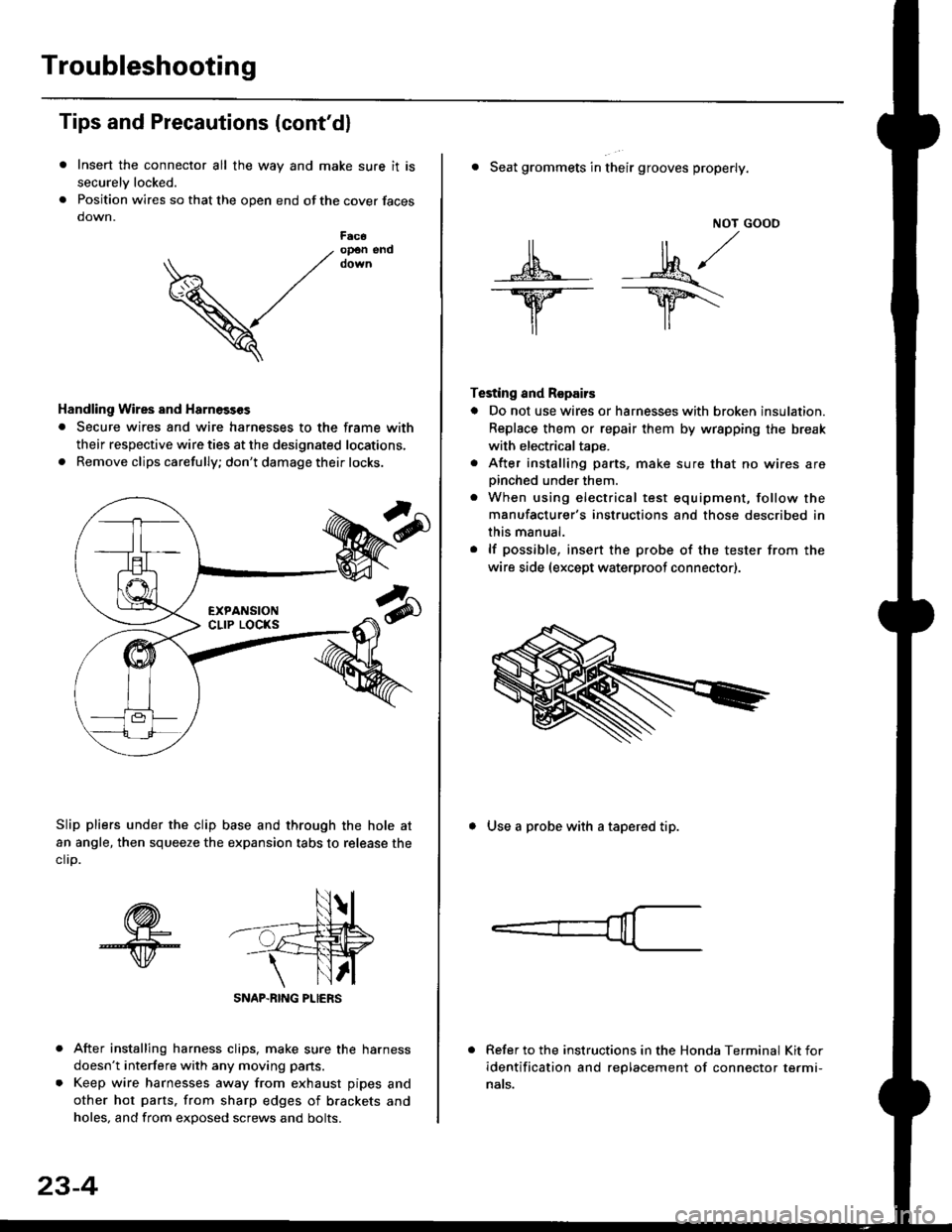
Troubleshooting
Tips and Precautions (cont'dl
Insert the connector all the way and make sure it is
securelv locked.
Position wires so that the open end of the cover faces
down.
After installing harness clips, make sure the harness
doesn't interfere with any moving pans.
Keep wire harnesses away from exhaust pipes and
other hot parts. from sharp edges of brackets and
holes, and from exDosed screws and bolts.
V
F6c6op€n end
Handling Wires and Harnosscs
. Secure wires and wire harnesses to the frame with
their respective wire ties at the designated locations,
. Remove clips carefully; don't damage their locks.
Slip pliers under the clip base and through the hole at
an angle, then squeeze the expansion tabs to release the
clrp.
SNAP-BING PLIERS
23-4
NOT GOOO
ll il,/
s*' -.1}8."/_Y--_Y5\
il ,,
Testing and Repairs
o Do not use wires or harnesses with broken insulation.
Replace them or repair them by wrspping the break
with electricaltaoe.
. After installing parts, make sure that no wires arepinched under them.. When using electrical test equipment, follow the
manufacturer's instructions and those described in
this manual.
. lf possible, insert the probe of the tester from the
wire side (except waterproof connector).
. Seat grommets in their grooves properly.
. Use a probe with a tapered tip.
Refer to the instructions in the Honda Terminal Kit for
identification and replacement of connector termi-
nats.
Page 1478 of 2189
Relay and Control Unit Locations
Dashboard: '96 - 97 models
CRUISE CONINOL UNIT
DAYTIMERUNNING LIG}ITSCONTROL UNITlCan!dal
IWire colo.s: GRN/ORN, GRN/RED,l
IWHT, YEL, and BLK I. MOONROOF CLOSE RELAYfwir. colorc: GRN/ORru, Cnru/VeLl
IWHT. GRN/RED, and ALK I
DASH LIGHTS BRIGHTNESS CONTROLLER{Has built-in control unit)
23-8