Page 151 of 2189

Cylinder HeadValve Seats
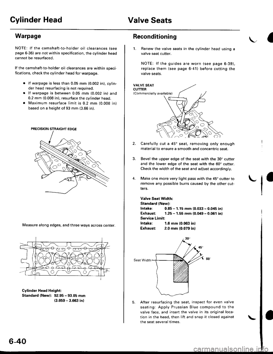
Warpage
NOTE: lf the camshaft-to-holder oil clearances (see
page 6-36) are not within specification, the cylinder head
cannot be resurfaced.
lf the camshaft-to-holder oil clearances are within sDeci,
fications, check the cylinder head lor warpage.
lf warpage is less than 0.05 mm (0.002 in), cylin-
der head resurfacing is not required.
lf warpage is between 0.05 mm (0.002 in) and
0.2 mm {0.008 in), resurface the cylinder head.
Maximum resurface limit is 0,2 mm (0.008 in)
based on a height of 93 mm (3.66 in).
Measure along edges, and three ways across center.
Cylinder Head Height:
Standard {Newl: 92.95 - 93.05 mm
{3.659 - 3.66:} in)
6-40
\
Reconditioning
'1. Renew the valve seats in the cylinder head using a
valve seat cutter.
NOTE: lf the guides are worn (see page 6-39).
replace them (see page 6-41) belore cutting the
valve seats.
VALVE SEATCUTTER(Commercially available)
2.
?
4.
Carefully cut a 45'seat, removing only enough
material to ensure a smooth and concentric seat.
Bevel the upper edge of the seat with the 30. cutter
and the lower edge of the seat with the 60' cutter.
Check the width of the seat and adjust accordingly.
Make one more very light pass with the 45" cutter to
remove any possible burrs caused by the other cut-
Iers.
Valve Seat Width:
Standard (N€w):
Intake: 0.85 - 1.15 mm 10.033 - 0.045 in)
Exhaust: 1.25 - 1.55 mm {0.049 - 0.061 in}
Sorvice Limit:
Intake: 1.6 mm (0.063 inl
Exhausl: 2.0 mm (0.079 in)
Seat Width
5. After resurfacing the seat, inspect for even valve
seatingr Apply Prussian Blue compound to the
valve face, and insert the valve in its original loca-
tion in the head, then liit and snap it closed against
the seat several times.
Page 152 of 2189

Valve Guides
7.
VALVESEAT
PFUSSIAN BTUE COMPOUNO
The actual valve seating surface. as shown by the
blue comDound, should be centered on the seat.
. lf it is too high (closer to the valve stem), you
must make a second cut with the 60'cutter to
move it down, then one more cut with the 45'
cutter to restore seat width,
. lf it is too low (closer to the vslve edge), you
must make a second cut with the 30" cutter to
move it uD, then one more cut with the 45'cutter
to restore seat width.
NOTE: The final cut should always be made with
the 45" cutter.
lnsert the intake and exhaust valves in the head and
measure the valve stem installed height.
Intake. Exhau3t Siem Installsd Height:
Standard (New): 53.17 - 53.6,4 mm
12.093 - 2.112 in)
Sorvice Limit: 53.89 mm (2.122 in)
lf the valve stem installed height is over the service
limit. reDlace the valve and recheck. lf its still over
the service limit, replace the cylinder head; the
valve seat in the head is too deep.
VALVE STEMINSTALLED HEIGHT
8.
\-
Replacement
1.As illustrated below, use a commercially-available
air-impact valve guide driver attachment modified
to fit the diameter of the valve guides. In most cases.
the same procedure can be done using the special
tool and a conventional hammer.
VALVE GUIDE DRIVERlCommerciallv available)5.3 mm
87 mm +- 57 mft
t3.43 in) | 12 24 inl
tr-r'10.8 mm(0.42 inl
or
VALVE GUIDE DRIVER, 5.5 mm
07742 - 0010100
Select the proper replacement guides. and chill them
in the freezer section of a refrigerator for about an
nour.
Use a hot plate or oven to evenly heat the cylinder
head to 300"F (150'C). Monitor the temperature with
a cooking thermometer.
CAUTION:
. Do not use a torch; it may warp the head.
Do not got the head hottel than 300"F (150"C1;
excessive heat may loosen thg valve seats.
To avoid burns. use heayy gloves whon handling
the heated cylinder h€ad.
{cont'd)
6-41
Page 154 of 2189

Valves
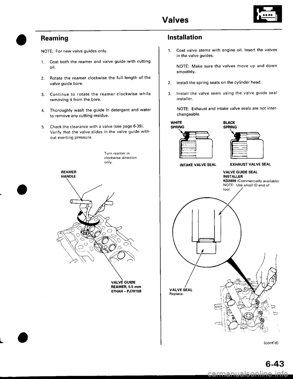
Reaming
NOTE: For new valve guides only.
1. Coat both the reamer and valve guide with cufting
orl.
2. Rotate the reamer clockwise the full length of the
valve guide bore.
3. Continue to rotate the reamer clockwise while
removing it from the bore.
4. Thoroughly wash the guide in detergent and water
to remove any cutting residue.
5. Check the clearance with a valve (see page 6-391.
Verify that the valve slides in the valve guide with-
out exerting Pressure.
Turn reamer inclockwise direclionon ly.
REAMER, 5.5 mmO7HAH. PJ'O'IOB
I
REAMER
oa)o,
o
o
1.
lnstallation
Coat valve stems with engine oil. Insert the valves
in the valve guides.
NOTE: Make sure lhe valves move up and clown
smoothly.
lnstallthe spring seats on the cylinder head.
Install the valve seals using the valve guide seal
installer.
NOTE: Exhaust and intake valve seals are not inter-
changeable.
2.
3.
WHITESPRINGBLACKSPRING
INTAKE VALVE SEALEXHAUST VALVE SEAL
VALVE GUIDE SEALINSTALLERKD2899 (Commercially available)NOTE: Use small lD end of
P
(cont'd)
6-43
Page 157 of 2189

Cylinder Head
Installation (cont'dl
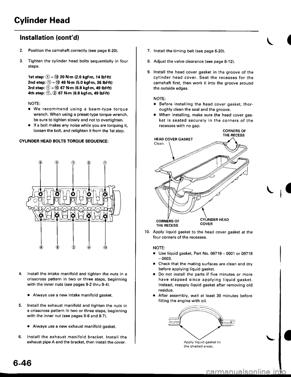
Position the camshaft correctly (see page 6-20).
Tighten the cylinder head bolts sequentially in four
steps.
rsr st.p: O - @ 20 N.m (2.0 kgf.m, 14 lbf'ft|
2nd srep: O - @ 49 N.m (5.0 kgf.m, 36 tbtft)
3rd stop; O - @ 67 N.m {6.8 kgf.m, /r9 lbl'ft}
4th st6p: O, O 67 N.m 16.8 kgf.m, 49 tbf.ftl
NOTE:
. We recommend using a beam-type torque
wrench, When using a preset-type torque wrench.
be sure to tighten slowly and not to overtighten.
. If a bolt makesany noisewhileyou aretorquing it,
loosen the bolt, and retighten it from the 1st step,
CYLINDER HEAD BOLTS TOROUE SEOUENCE:
Install the intake manifold and tighten the nuts in a
crisscross pattern in two or three steps, beginning
with the inner nuts (see pages 9-2 thru 9-4).
. Always use a new intake manifold gasket.
Install the exhaust manifold and tighten the nuts in
a crisscross pattern in two or three steps, beginning
with the inner nut {see pages 9-6 and g-7).
. Always use a new exhaust manifold gasket.
Install the exhaust manifold bracket. lnstall the
exhaust pipe A and the bracket, then install the cover.
4.
6-46
\-
(
7.Installthe timing belt (see page 6-20).
Adjust the valve clearance (see page el2),
Install the head cover gasket in the groove of the
cylinder head cover, Seat the recesses for the
camshaft first, then work it into the groove around
the outside edges.
NOTE:
. Before installing the head cover gasket, thor-
oughly clean the seal and the groove.
. When installing, make sure the head cover gas-
ket is seated securely in the corners of the
recesses wath no gap.
COBNERS OFTHE RECESS
CORNERS OFTHE REcEss covEB
Apply liquid gasket to the head cover gasket at the
four corners of the recesses.
NOTE:
. Use liquid gasket, Pan No. 08718 - 0001 or 08718- 0003.
. Check that the mating surfaces are clean and dry
before applying liquid gasket.
. Do not install the parts if five minutes or more
have elapsed since applying liquid gasket.
Instead, reapply liquid gasket after removing old
residue.
. After assembly, wait at least 30 minutes before
filling the engine with oil.
8.
9.
I
10.
Page 168 of 2189
Valve Clearance
I
I
I
Adjustment {cont'd)
5. Tighten the locknut and recheck clearance.Repeat adjustment if necessary.
Rotate the crankshaft 180. counterclockwise(camshaft pulley turns 90'). The "Up" mark shouldbe on the exhaust side. Adjust valves on No. 3 cylin-der.
Number 3 piston at TDC:
FE€LER GAUGE
"UP- MARKS
6-58
7. Rotate the crankshaft '180. counterclockwise tobring No. 4 piston to TDC. The ,,Up,. mark shouldbe pointing straight down. Adjust valves on No. 4cylinder.
Number 4 piston at TDC:
8, Rotate the crankshaft 180. counterclockwise tobring No. 2 piston to TDC. The "Up., marks shouldbe on the intake side. Adjust valves on No. 2 cylin_der.
Number 2 piston at TDC:
L
Page 173 of 2189
7.
8.
Remove the crankshaft pulley (see page 6-59).
Remove the cylinder head cover'
NOTE: Refer to page 6-86 when installing the cylin-
der head cover.
Remove the middle cover and lower cover.
NOTE: Do not use the middle and lower covers for
storing removed items.
MIDDLE COVER
LOWER COVER
9.
10.Loosen the adjusting bolt 180'.
to remove tension from the
retighten the adjusting bolt.
9.8 N.m lt.o kgf m,
7.2lw'ftl
Push the tensioner
timing belt, then
N.m (5.5 kgt'm,
1 1. Remove the timing belt.
TDC
lnstallation
Install the timing belt in the reverse order of removal;
Only key points are described here.
1. Set the timing belt drive pulley so that the No. 1 pis'
ton is at top dead center (TDC). Align the groove on
the timing belt drive pulley to the V pointer on the
oil pumP.
set the camshaft pulleys so that the No. 1 piston is at
TDC.
Align the TDC marks on the intake and exhaust cam-
shaft pulleys.
MARK
(cont'd)
6-63
POINTER
Page 174 of 2189

Timing Belt
lnstallation (cont'dl
3. Install the timing belt tightly in the sequence shown.
@ Timing belt drive pulley (crankshaft) + @Adjusting pulley * @ Water pump pu ey + @ Intakecamshaft pulley + @ Exhaust camshaft pulley,
NOTE: Make sure the timing belt drive pulley andcamshaft pullevs are at TDC,
Loosen and retighten the adjusting bolt to tensionthe timing belt.
Install the lower cover and middle cover.
NOTE: Clean the middle and lower covers beforeinstalling.
Install the crankshaft pulley, then tighten the pulleybolt (see page 459).
Rotate the crankshaft pulley about five or six turnscounterclockwise so that the timing belt positions onthe pulleys.
Adjust the timing belt tension (see page A611.
7.
6-64
a
9. Check that the crankshaft pulley and camshaft pul-leys are both at TDC.
CRANKSHAFT PULLEY
CAMSHAFT PULLEY:
lf the camshaft and crankshaft pulleys are not posi-tioned at TDC, remove the timing belt, adjust theposition following the procedure on page &63, thenreinstall the timing belt.
After installation, adjust the tension of each belt.
. See section 23 for alternator belt tension adjust-ment.
. See section 22lor NC compressor belt tensionadiustment,
. See section 17 for P/S pump belt tension adjust-ment.
'l
10.
11.
I
"UP" MARKS
Page 175 of 2189
Cylinder Head
lllustrated Index
CAUTION:
. To avoid damaging the cylinder head, wait until the engine coolant tempsraturo drops below 100"F (38"C1 bofote
removing it,
. when handling a metal gasket, take caro not to fold the gaskot or damage the contact surface of the gasket.
NOTE: Use new O-rings and gaskets when reassembling.
CYLINDER HEAO
PLUGReplace.
)@
DISTRIBUTOR
8 x 1 ,25 mm
27 N.m P.E kgl m.
20 tbf.foApply engine oil to
the threads.
cr.rMp.S
CAMSHAFT A"o''*t*'; wes@
OIL SEALReplace.
6 x l,omm9.8 N'm tl.0 kgt'm,7.2lbf ft)
RUBBER SEALReplace when damaged
or detedorated.
6x1.0mm9.8 N.m (1.0 kgf'm,
7.2 rbnftl
fi%
IGNMONWIRE COVER
CYLINOER HEAD
COVERRefer to page 6-86
when installing
HEAD COVER GASKETReplace when leaking, damaged
or deteriorated.Apply liquid gasket at thecorners of the recesses, Page 6-86
8 x 1,25 mm24 N.m {2.4 kgf'm,
1? tbf.ftl
EXHAUST
10 x 1.25 mm56 N.m (5.7 kgf m,,r1 lbl.ft)
(cont'd)
6-65