Page 1416 of 2189
Heater Control Panel
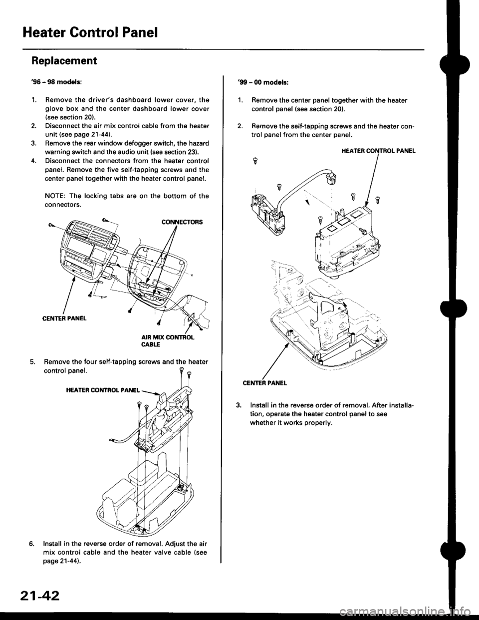
'95 - 98 modolsi
Remove the driver's dashboard lower cover, the
glove box and the center dashboard lower cover(see section 20).
Disconnect the air mix control cabls from the heater
unit {see page 21-44).
Remove the rear window defogger switch, the hazard
warning switch and the audio unit (see section 23).
Disconnect the connectors from the heater control
panel. Remove the five self-tapping screws and the
center panel together with the heater control panel.
NOTE: The locking tabs are on the bottom of the
connecrors.
Install in the .everse order of removal. Adjust the air
mix control cable and the heater valve cable {seepage 21-44)..
Replacement
1.
Remove the four self-tapping screws and the heater
21-42
1.
'9!, - 00 modols:
Remove the center panel together with the heater
control panel (see section 20).
Remove the self-tapping screws and the heater con-
trol panelfrom the center Danel.
Install in the reverse order of removal. After
tion, operate the heater control panel to see
whether it works properly.
installa-
Page 1417 of 2189
Overhaul -'96 - 98 Models
HEATER FAN SWITCHTest, page 21-49
Air Mix Control Cable Replacomenl
1. Cut the inner cable on the lever side of the cable holder, then remove both pieces of the inner cable.
2. Using a sharp knife, cut completely through the end of the cable housing at the two locations.
3. Slidethe largesection ofthecable housing outofthe cable holder, being careful not to da mage the cable stops.
4. Carefully remove the cut pieces of the cable housing with a small flat tip screwdriver.
5. Hook the tip of the new air mix control cable to the temperature control lever, then push the cable housing into the
cable holder until it locks into place.
NOTE: After assembly, check that the temperature control lever slides smoothly through the full stroke lrom right to left.
21-43
Page 1418 of 2189
Temperature Control
Adjustment -'96 - 98 Models
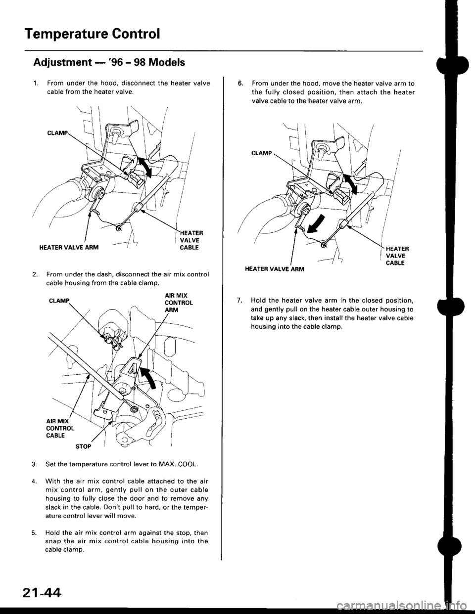
1. From under the hood, disconnect the heater valve
cable from the heater valve.
TERVALVECABLEHEATER VALVE ARM
2.From under the dash, disconnect the air mix control
cable housing from the cable clamp,
AIR MIXCONTROLARM
3.Set the temperature control lever to MAX. COOL.
With the air mix control cable attached to the air
mix control arm, gently pull on the outer cable
housing to fully close the door and to remove any
slack in the cable. Don't pullto hard, or the temper-
ature control lever will move.
Hold the air mix control arm against the stop. then
snap the air mix control cable housing into the
cable clamp.
21-44
6. From under the hood. move the heater valve arm to
the fully closed position. then attach the heater
valve cable to the heater valve arm.
7. Hold the heater valve arm in the closed position,
and gently pull on the heater cable outer housing to
take up any slack. then install the heater valve cable
housing into the cable clamp.
HEATER VALVE ARM
Page 1419 of 2189
Adjustment -'99 - 00 Models
1. From under the hood, open the cable clamp, then
disconnect the heater valve cable from the heater
valve arm.
From under the dash. disconnect the heater valve
cable housing from the cable clamp, and disconnect
the heater valve cable from the air mix control arm.
HEATER VALVE CABLE
Set the temperature control dial on MAX COOL with
the ignition switch ON {ll).
Attach the heater valve cable to the air mix control
arm as shown above. Hold the end of the heater
valve cable housing against the stop, then snap the
heater valve cable housing into the cable clamp.
HEATER VALVE ARM
5. From under the hood. turn the heater valve arm to
the fullv closed oosition as shown, and hold it,
Attach the heater valve cable to the heater valve
arm, and gently pull on the heater valve cable hous-
ing to take up any slack, then install the heater valve
cable housing into the cable clamp.
HEATER VALVE ARM
21-45
Page 1420 of 2189
Air Mix Gontrol Motor
't.
Test -'99 - 00 Models
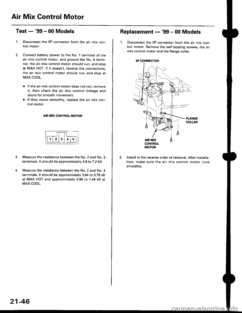
Disconnect the 5P connector from the air mix con-
trol motor.
Connect battery power to the No. 1 terminal of the
air mix control motor, and ground the No. 5 termi,
nal; the air mix control motor should run, and stop
at MAX HOT. lf it doesn't, reverse the connections;
the air mix control motor should run, and stop at
MAX COOL.
lf the air mix control motor does not run, remove
it, then check the air mix control linkage and
doors for smooth movement.
lf they move smoothly, replace the air mix con-
trol motor.
AIR MIX CONTROL MOTOR
Measure the resistance between the No.2 and No.3
terminals. lt should be approximately 4.8 to 7.2 kO.
Measure the resistance between the No. 2 and No. 4
terminals. lt should be approximately 3.84 to 5.76 kO
at MAX HOT and approximately 0.96 to 1.44 kO at
MAX COOL.
21-46
5P OONNECYOB
Replacement -'99 - 00 Models
1, Disconnect the 5P connector from the air mix con-
trol motor. Remove the self-tapping screws, the airmix control motor and the flange collar.
CONTROLMOTOR
Install in the reverse order of removal. After installa-
tion, make sure the air mix control motor runs
smoothly.
Page 1429 of 2189
Description
Outline
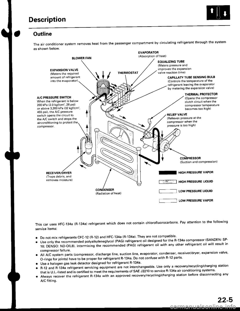
The air conditioner system removes heat from the passenger compartment by circulating refrigerant through the system
as shown below.
BLOWER FAN
EVAPORATOR(Absorption of heati
EOUALIZING TUBE(Meters pressure andimproves the expansionvalve reaction time)
into the evaporator)CAPILLATY TUBE SENSING BULB
lControls the temPerature of the
ref rigerant leaving the evaporator
by metering the expansion valve)
/\
THERMOSTAT
A/C PRESSURE SWITCH
When the refrigerant is below
200 kPa (2.0 kgtcm'�,28 Psi)or above 3,200 kPa 132 kgflcm',
455 psi), the Ay'C pressure
switch opens the circuit to
the A,/C switch and stops the
EXPANSION VALVE(Meters the requiredamount of refrigerant
airconditioning to Protect the
compressor.
RECEIVER/DRYER(Traps debris, andremoves morsturel
THERMAL PROTECTOR
{Opens the comPressorclutch circuit when the
compressor temPeraturebecomes too high)
RELIEF VALVE(Relieves pressure at the
compressor when thepressure is too high)
(Radiation of heat)
I
f-r-�-; I
(Suction and comPression,
HIGH PRESSURE VAPOR
HtGH PRESSUBE LIOUID
LOW PRESSURE LIOUID
This car uses HFC-134a (R-134a) refrigerant which does not contain chlorofluorocarbons Pay attention to the following
service items:
. Do not mix refrigerants CFC-12 (R-12) and HFC-134a (R-134a)' They are not compatible'
. Useonlythe recommended polyalkyieneglycol (PAG) refrigerant oil designedforthe R-134a compressor (SANDEN: SP-
10; DENSO: ND_OIL8). Intermixing ihe re-commended (pAG) refrigerant oil with any other refrigerant oil will result in
compressor failure.
. All A,,ic system parts {compressor, discharge line, suction line, evaporator, condenser, receiver/dryer, expansion valve'
O-rings for joints) have to be proper for refrigerant R- 134a Do not confuse with R-l2 parts'
. Use a halogen gas leak detector designed for refrigerant R-134a
. R-12 and R-134a refrigerant servacing equipment are not interchangeable. Use only a recovery/recycling/charging station
that is u,L.-listed and is certified to meet the requirements of sAE J2210 to service R-134a air conditioning systems'
. Always recover the refrigerant R-134a with an approved recovery/recycling/charging station before disconnecting any
A,/C fitting.
S]
22-5
Page 1448 of 2189
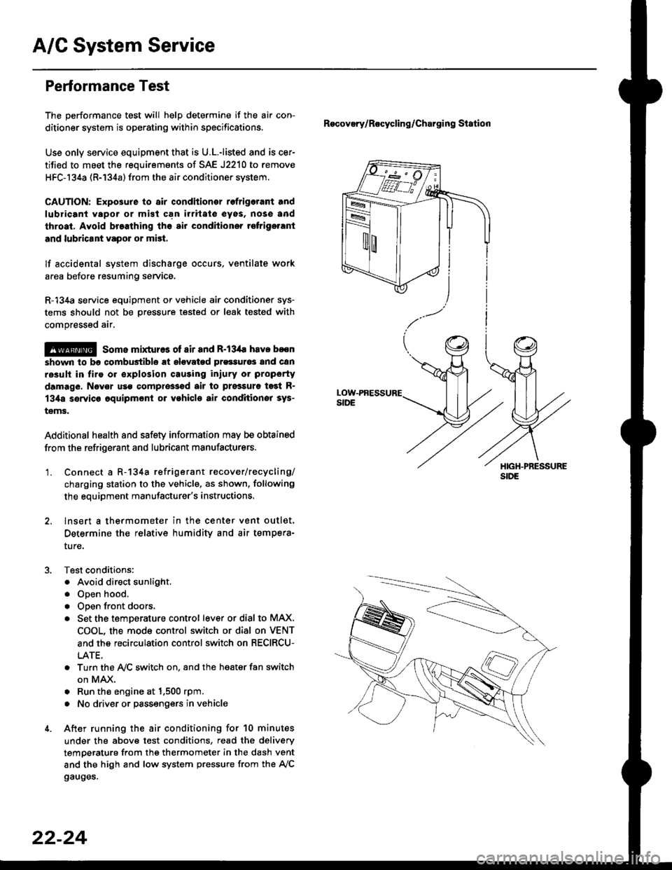
A/C System Service
Performance Test
The performance test will help determine if the air con-
ditioner system is operating within specifications.
Use only service equipment that is U.L.-listed and is cer-
tified to meet the reouirements of SAE J2210 to remove
HFC-134a (R-134a) from the air conditioner system.
CAUTION: Exposure to air conditionor rofrigerant and
lubricant vapor or mist can irrilalo €yes, nose and
throat. Avoid breathing tho air conditioner rstrigerrnt
and lubricant vapor or mist,
lf accidental system discharge occurs, ventilate work
area before resuming service.
R-134a service equipment or vehicle air conditioner sys-
tems should not be pressure tested or leak tested with
compressed air.
@ some mixtur$ of air and R-134a have been
shown lo b9 combustible rt glgvatad pr€ssur63 and can
resull in tire 01 oxplosion causing inlury ot property
damage. Never uao compre33ed air to pressure t99t R-
134a ssrvico 6quipmsnt or vohicla air conditioner sys-
tems.
Additional health and safety information may be obtained
from the refrigerant and lubricant manufacturers.
'1. Connect a R-134a refrigerant recover/recycling/
charging station to the vehicle, as shown, following
the equipment manufacturer's instructions.
2. lnsert a thermometer in the center vent outlet.
Determine the relative humidity and air tempera-
ture,
Test conditions:
. Avoid direct sunlight.
. Open hood.
. Open front doors.
. Set the temDerature control lever or dial to MAX,
COOL, the mode control switch or dial on VENT
and the recirculation control switch on RECIRCU-
LATE.
. Turn the A,/C switch on. and the heater fan switch
on MAX.
. Run the engine at 1,500 rpm.
. No driver or passengers in vehicle
After running the air conditioning for 10 minutes
under the above test conditions, read the delivery
temperature from the thermometer in the dash vent
and the high and low system pressure from the A,/C
gauges.
Recovery/Rocycling/Charging Station
22-24
Page 1529 of 2189
'
Heater Sub-harness A: '99 - 00 models
Connector or
Terminal
Number of
CavitiesLocationConnects toNotes
c721
c722
c723
c724
c725
c726
c727
c728
c729
c730
7
24
3
2
4
1
5
4
Under left side of dash
Behind glove box
Behind glove box
Behind glove box
Behind glove box
Behind glove box
Behind glove box
Behind glove box
Behind glove box
Behind glove box
Main wire harness (C440)
Mode control motor
Heater sub-harness B (C741)
lilc thermostat
Blower motor
Power transistor
Recircuiation control motor
Heater sub-harness B (C744)
Air mix control motor
Blower motor high relaY
Heater Sub-harness B: '99 - 00 models
HEATER SUB.HARNESS A
Connector or
Terminal
Number of
CavitiesLocationConnects toNotes
c7 41
c'742
c143
c744
20
8
20
1
Behind glove box
Behind middie of dash
Behind middle of dash
Behind glove box
Heater sub-harness A (C723)
Heater control Panel
Heater control Panel
Heater sub-harness A (C728)