2000 HONDA CIVIC Vehicle Speed Sensor
[x] Cancel search: Vehicle Speed SensorPage 692 of 2189

Description
Electronic Control System (cont'd)
Shift Control
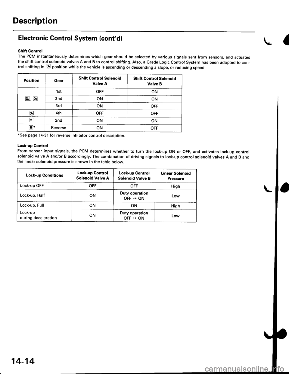
The PCM instantaneously determines which gear should be selected by various signals sent from sensors, and actuatesthe shift control solenoid valves A and B to control shifting. Also. a Grade Logic Control System has been adopted to con-trol shifting in E position while the vehicle is ascending or descending a slope, or reducing speed.
PoshionGearShift Control Solenoid
Vslve A
Shift Control Solenoid
Valve B
8,tr
1stOFFON
2ndONON
3rdONOFF
E4thOFFOFF
tr2ndONON
E-ReverseONOFF
*See page 14-31 for reverse inhibitor control description.
Lock-up Control
From sensor input signals, the PCM determines whether to turn the lock-up ON or OFF, and activates lock-up controlsolenoid valve A and/or B accordingly. The combination of driving signals to lock-up control solenoid valves A and B andthe linear solenoid pressure is shown in the table below.
Lock-up ConditionsLock-up Control
Solenoid Valvo A
Lock-up Control
Solenoid Valve B
Linoar Solonoid
Prggguro
Lock-up OFFOFFOFFHigh
Lock-up, HalfONDuty operation
OFF * ONLow
Lock-up, FullONONHigh
LOCK-Up
during decelerationONDuty operation
OFF - ON
a
14-14
Page 693 of 2189

GRADE LOGIC CONTROL SYSTEM
How it works:
The pCM compares actual driving conditions with driving conditions memorized in the PCM, based on the input from the
vehicle speed sensor, the throttle position sensor, the barometoric pressure sensor, the engine coolant temperature sensor,
the brake switch signal, and the shift lever position signal, to control shifting while a vehicle is ascending or descending a
slope, or reducing speed.
SIGNALS OETECTED
O.iving Resi3lence
Judgemenl ot Conirolling Arca
. Ascending mod€
lFuzzy loqicl. Gradual Ascending mode' Ste€p Ascending mode. Oescending mode. Gr.du.l Descending mode. Steep D6cending mode
14-15
Page 721 of 2189

I
PCM CONNECTOR B {25P1 {cont'dl
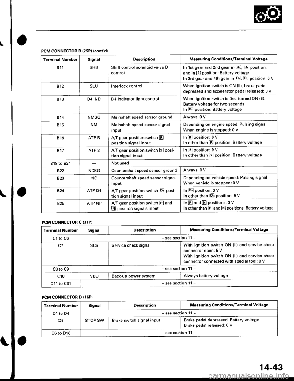
Terminal NumberSignalDescriptionMeasuring Conditions/Terminal Vohage
811SHBShift control solenoid valve B
control
In 1st gear and 2nd gear in -q1, q11 position,
and in E] position: Battery voltage
In 3rd gear and 4th gear in lD.J, [Dr- position: 0 V
B't2SLUInterlock controlWhen ignition switch is ON (ll), brake pedal
deoressed and accelerator Dedal released: 0 V
813D4 INDD4 Indicator light controlWhen ignition switch is first turned ON (ll):
Battery voltage for two seconds
In E position: Baftery voltage
B't 4NMSGMainshaft speed sensor groundAlways: 0 V
E tcNMMainshaft speed sensor signal
input
Depending on engine speed: Pulsing signal
When engine is stopped: 0 V
816ATP RAy'T gear position switch Eposition signal input
InE position: 0V
In other than E position: Battery voltage
817ATP 2A/T gear position switch E posi-
tion signal input
InE position: 0V
In orher than E position: Battery voltage
818 to 821Not used
s22NCSGCountershatt speed sensor groundAlwaysr 0 V
B�23NCCountershaft speed sensor signal
input
Depending on vehicle speed: Pulsing signal
When vehicle is stopped: 0 V
B�24ATP D4Ay'T gear position switch lor posi-
tion signal input
InEposition:0V
In other than 6 position: 5 V
ATP NPA,/T gear position switch E and
N position signals input
InE and E positions: 0V
In otherthan E and N] positions: Battery voltage
PCM CONNECTOR C {31P)
Terminal NumberSignalDescriptionMeasuring Conditions/Terminal Voltage
Cl to C6- see section 11 -
c1Service check signalWith ignition switch ON (ll) and service check
connector oDen; 5 V
With ignition switch ON (ll) and service check
connector connected with sDecial tool: 0 V
C8 to Cg- see section 11 -
c10VBUBack-up power systemAlways battery voltage
C11 to C31- see section '11 -
PCM CONNECTOR D (16P}
Terminal NumberSignalDescriptionMeasuring Conditions/Terminal Voltage
Dl to D4- see section 11 -
D5STOP SWBrake switch signal inputBrake pedal depressed: Battery voltage
Brake pedal released: 0 V
D6 to D16- see section 1 l -
14-43
Page 725 of 2189

FCM CONNECTOR D {16P)
\o
14-47
Terminal NumberSignalDo3criptionMeasuring Conditions/Torminal Vohage
D1LCALock-up control solenoid valve A
control
When lock-up is ON: Battery voltage
With no lock-up: 0 V
SHBShift control solenoid valve B
control
In E position, in 1st and 2nd gear in E, E
position: Battery voltage
ln 3rd gear in E, E, in 4th gear in E posi-
tion;0 V
D3LCBLock-up control solenoid valve B
control
When full lock-up: Battery voltage
With half lock-up: Pulsing signal
D4Not used
D5VB SOLLock-up control solenoids, shift
control solenoids and linear
solenoid power supply electrode
with ignition switch oN (ll): Battery voltage
With ignition switch OFF: 0 V
D6ATP RAy'T gear position switch
E position input
tnEposition:0V
In other than E position: Approx. 10 V
SHAShift control solenoid valve A
control
In E] position, in 2nd and 3rd gear in p!, [Q]
position: Battery voltage
In 1st gear in E, @ position, in 4th gear in El
Dosition: 0 V
D8ATP D3A/T gear position switch
E position input
In E position:0V
In otherthan @ position: Approx. 10 V
D9ATP D4Ay'T gear position switch
E position switch
In El position: 0 V
In other than E position: Approx. 5 V
D10NCCountershaft speed sensor signal
input
Depending on vehicle speed: Pulsing signal
When vehicle is stooped: 0 V
D11NMMainshaft speed sensor signal
Inpur
Depending on engine speed: Pulsing signal
When engine is stopped: 0 V
D't2NMSGMainshaft speed sensor ground
D13ATP NPAy'T gear position switch E and
E position input
InE and E positions: 0V
In other than E and E positions: Approx. 10 V
D14AfP 2Ay'T gear position switch
E position input
tnEposition;0V
In other than E position: Approx. 10 V
D16NCSGCountershaft speed sensor
ground
Page 771 of 2189

Troubleshooting Flowchart - Countershaft Speed Sensor
NOTE: Record all freeze data before you troubleshoot
Po$iblo Cause
. Loos€ or fsulty conneclionbetween the PCM and vehicle
hainoss' Disconnectod countersh.ft
spoed senaof connoctor. Short or opgn in counteBhaft
3Deed aensor wire. Faulty counloEhaft 3p€ed sen'
soa
COUNTERSHAFf SPEED
SENSOR CONNESTOR
Terminal side oI male terminals
FCM CONNECTOR D I16PI
rconl c
1+93
NC IBLUI
. OBD ll Scan Tool indicat6 Code
PO720.. Self-diagnosis E indicator light
blinks nin6times.
Check the countershaft sPeed
sensor installation, and check it
lor damage.
ls the countershaft speed sensor
installed properly, and not dam-
aged?
Reinstall or replace and rechock.
Measurg Counlershatt SPeed
Sgn3ol R6istance at tho Son3ol
Connector:1. Disconnect the 2P connector
from the countershaft sPeed
sensor.2, Measuro countershaft sPeed
sensor resistanca at the sensor
connector.
ls the resistance 400 - 600 O?
Chcck CounteEh.tt SPeed Sen'
sor lor a Short Circuit:1. Disconnect the D {16P) con
nector trom the PCM.2. Check lor continuity between
body ground and the D10 ter_
minal and D16 terminal indi-
vid!ally.
R6oai. short in tl|€ wi.6a bstwa€n
the D10 and D16 t.rminali end
tho countdthatt rP€od senaor.
To page 14 94
Wire side of temale terminals
Page 791 of 2189

Road Test
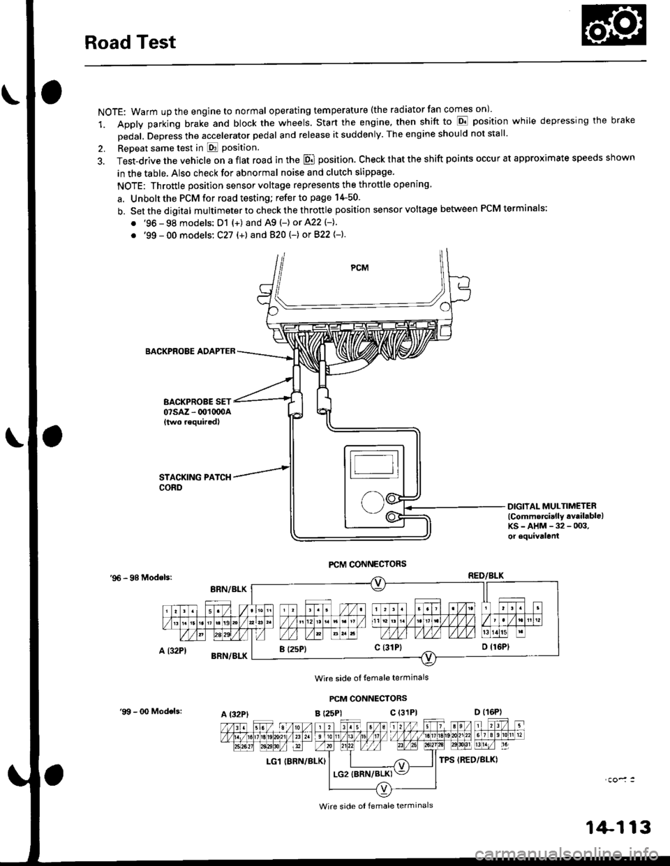
NOTE: Warm up the engine to normal operating tem peratu re (the rad iator fan comes on )'
1. Apply parking brake and block the wheels. Start the engine, then shift to E position while depressing the brake
Dedal, Depress the accelerator pedal and release it suddenly. The engine should not stall'
2. Repeat same test in E Position.
3. Test-drive the vehicle on a flat road in the E position. Check that the shift points occur at approximate speeds shown
in the table. Also check for abnormal noise and clutch slippage.
NOTE: Throttle position sensor voltage represents the throttle opening
a. Unbolt the PCM for road testing; refer to page 14-50.
b. Setthedigital multimeter to check the th rottle position sensor voltage between PCM terminals;
. '96 - 98 models: D1 {+) and A9 (-) or 422 (-}.
. '99 - 00 models: C27 (+) andB20t-) orB22{-}.
BACKPROBE ADAPTER
BACKPROBE SET07sAz - 001oq)A{two requiredl
DIGIIAL MULTIMETERlCommercially available)KS-AHM-32-003,or equivalenl
'96 - 98 Modelsr
Wire side ol temale terminals
PCM CONNECTORS
B t25Pl c (31P)
LG1 IBRN/BLK)
I (25P1c (31P}
A t32PtD (16P)
Wire side ol female terminals
'9!t - 00 Models:
1+113
Page 800 of 2189

Transmission
Removal
@Maks sure lifts, iacks and safety stands are placedproperly, and hoist bracket ate aftached to the cor_rec{ position on the engine lsee section 1).Apply parking brake and block rear whoels so vehiclewill not roll off stands and fall on you while workingunder it.
CAUTION: Use tender covers to avoid damaging paint-ed surfaces.
1, Disconnect the battery negative (_) terminal fromthe battery, then remove the positive (+) terminal.
2. Remove the intake air duct.
D16Y7 engins:
Remove the intake air duct and resonator.
D16Y8 engine:
Remove the intake air duct and the air cleaner hous-ing assembly,
3. Remove the starter cables and cable holder fromthe starter motor.
MOTOR CABLE
MOTOR CABLE
14-122
4. Remove the transmission ground cable, and discon_nect the lock-up control solenoid connector.
LOCK.UP CONTROLSOLENOID CONNECTOR
5, Disconnect the vehicle speed sensor (VSS) connec_tor and the countershaft speed sensor connector.
VEHICLE SPEED
Page 873 of 2189

Description
The Continuously Variable Transmission (CVT) is an electronically controlled automatic transmission with drive and driv
en Oullevs, and a steel belt. The CVT provides non stage speeds forward and one reverse. The entire unit is positioned in
line with the engine.
Transmission
Around the outside of the flywheel is a ring gear which meshes with the starter pinion when the engine is being staned.
The transmission has four parallel shafts: the input shaft, the drive pulley shaft. the driven pulley shaft, and the secondary
gear shaft. The input shaft is in line with the engine crankshaft. The drive pulley shaft and the driven pulley shaft consist of
movable and fixed face pulleys. Both pulleys are linked by the steel belt.
The input shaft includes the sun gear. The drive pulley shaft includes the forward clutch which mounts the carrier assem-
bly on the forward clutch drum. The carrier assembly includes the pinion gears which mesh with the sun gear and the ring
gear. The ring gear has a hub-mounted reverse brake disc.
The driven pulley shaft includes the start clutch and the secondary drive gear which is integral with the park gear' The sec-
ondary gear shaft is positioned between the secondary drive gear and the final driven gear. The secondary gear shaft
includes the secondary driven gear which serves to change the rotation direction. because the drive pulley shaft and the
driven oullev shaft rotate the same direction. When certain combinations of planetary gears in the transmission are
engaged by the clutches and the reverse brake, power is transmitted from the drive pulley shaft to the driven pulley shaft
to provide E, E, E, and El.
Electronic Control'96 - 98 Models:
The electronic control system consists of the Transmission Control Module (TCM), sensors, three linear solenoids, and a
inhibitor solenoid. Shifting is electronically controlled under all conditions'
The TCM is located below the dashboard, behind the kick panel on the driver's side.'99 - 00 Models:
The electronic control svstem consists of a Powertrain Control Module (PCM), sensors, three linear solenoids and an
inhibitor solenoid. Shifting is electronically controlled under all conditions. A Grade Logic Control System to control shift-
ing in E position while the vehicle is ascending or descending a slope.
The PCM is located below the dashboard, under the kick panel on the passenger's side.
Hydraulic Control
The lower valve body assembly includes the main valve body, the Pressure Low (PL) reguiator valve body, the shift valve
body, the start clutch control valve body, and the secondary valve body. They are positioned on the lower part of the
transmission housing.
The main valve body contains the Pressure High (PH) control valve, the lubrication valve, and the pitot regulator valve.
The secondary valve body contains the PH regulator valve, the clutch reducing valve, the start clutch valve accumulator,
and the shift inhibitor valve. The PL regulator valve body contains the PL regulator valve and the PH-PL control valve
which is ioined to the PH,PL control linear solenoid. The inhibitor solenoid valve is bolted on the PL regulator valve body.
The shift valve body contains the shift valve and the shift control valve. which is joined to the shift control linear solenoid.
The start clutch control valve body contains the start clutch control valve, which is joined to the start clutch control linear
solenoid. The linear solenoids and the inhibitor solenoid are controlled by the TCM or PCM. The manual valve body which
contains the manual valve and the reverse inhibitor valve, is bolted on the intermediate housing.
The ATF pump assembly is located on the transmission housing, and is linked with the input shaft by the sprockets and
the sprocket chain. The pulleys and the clutch receive fluid from their respective feed pipes, and the reverse brake receives
fluid from internal hydraulic circuit.
Shift Control Mechanism
Input from various sensors located throughout the vehicle determines which linear solenoid the TCM or PCM will activate.
Activating the shift control linear solenoid changes the shift control valve pressure, causing the shift valve to move. This
pressurizes the drive pulley pressure to the drive pulley and the driven pulley pressure to the driven pulley and changes
their effective pulley ratio. Activating the start clutch control linear solenoid moves the start clutch control valve. The start
clutch control valve uncovers the port, providing pressure to the start clutch to engage it(cont'd)
14-195
,!