Page 266 of 2189

EGT Switch
-f
Testing
Replace the thermostat if it is open at room temperature'
To test a closed thermostat:
1, Suspend the thermostat in a container of water as
shown.
THEBMOMETER
THERMOSTAT
Heat the water, and check the temperature with a
thermometer. Check the temperature at which the
thermostat first opens, and at which it is fully open
CAUTION: Do not let the thermometer touch the
bottom of the hot Gonlainel.
Measure lift height of the thermostat when fully
open.
STANDARD THERMOSTAT
Lift height above 8.0 mm (0.31 inl
Starts opsning: 169' - 176'F (76' - 80'Cl
Fully open: 194'F {90"C1
!'o
10-1 1
Testing
!!@ Romoving the EcT swhch while lhs engine
i!-ot can cause the coolant to sPray out, seriously scald-
ing you. Always lst th€ ongine and rediator cool down
before removing ihe ECT switch.
NOTE: Bleed air from the cooling system after installing
the ECT switch (see Page 10-7)
1. Remove the ECT switch from the thermostat hous-
ing (see Page'10-10).
2. Suspend the ECT switch in a container of water as
shown.
Heat the water, and check the temperature with a
thermometer.
CAUTION: Do not let the thermomoter touch tho
bottom of the hot container'
Measure the resistance between the A and B termi-
nals according to the table.4.
Terminal
Oo"rffi
swlTcH
ON196' - 203"F
(91" - 95'C)o--o
OFF
5" - 15'F {3" - 8'C)
lower than the temPera-
ture when t goes on
Page 270 of 2189

!
Fuel and Emrsslons
SoecialToofs .....,...."..,. 11-2
Component Locations
lndex ....................., ......... 11-3
Svstem Description
Vacuum Connections ................,,..,.. ......... 11-12
Electrical Connections ...............,.,.,... ....... 11-29
System Connectors ........,.,.,.......................... 1 1-51
Troubleshooting
Troubleshooting Procedures ................. .. 11-81
Engine Control Module/PowertrainControl Module TerminalAfiangement ....,.,..... 11-88
Diagnostic Trouble Code Chart .................,., 11.97
How to Read Flowcharts .,.......................... . 11-103
PGM-Fl System
System Description ...... 11-10,1
Troubleshooting Flowcharts
Engine Control Module/PowertrainContlol Module ........ 11-107
Manitold Absolute Pressure Sensor .....'. . ... 11-115
fntake Air Temperatuie Sensor ..... . . ., . 11'121
Engine Coolant Temperatuae Sensol ........., 11-128
Throttle Position Sensor ...................,........... 11-132
Primary Heated Orygen Sensor (Sensor 1l ... 11-139
Secondary Heated Oxygen Sensor(Sensor 21.................................................... 1 1-153
Heated Oxygen Sensor Heater ...................,. 11-157
Fuel Supply System ...... 11-164
Random Mislire ......., ..11-166
Misfire Detected in One Cylindsr ................. 11-167
Knock Sensor .,.,............ 11-170
CKP/TDC/CYP Sensor ................................... 11'172
Vehicle Speed Sensor ...........,......,...,.,........... 1t-176
Barometric Pressure Sensor ...............,......... I 1-178
Electrical Load Detector,.,,............................ 1 1-179
CKF Sensor .................... 11-183
ECM/PCM Internal Circuit ............................. I 1-188
A/T Signal {TMA/TMBI .................................. I 1-189
ldle Control System
System Doscriplion ............ 11-190
Troubleshooting Flowcharts
ldle Control System ...... 11-192
ldle Air Control Va1ve .................................... I 1-19i1
Starter Switch Signal .................................... 1 1'202
Air Conditioning Signal ................................. 11'201
Ahernator FR Signal .................................... . 1 1-208
BrakeSwitch Signal ..................................... f 1"210
Power Sleering Prossure Switch Signal ......11-212
A/T Gear Position Signal ............................... 11-216
Clutch Swiich Signal ................................-.... 11-214
ldte Speed Setting . .............11-220
Fuel Supply System
Fuel Lines .,...................,.,.,.,11-221
Fuef Tube/Ouick-Connect Fittings ..........,.,........ 11 -227
System Description ....'.... 11-230
Fuel Pressure .......,.,,........... 11-230
Fuef fniectors ......................11-232
Fu€f Pressure Regulator .....,.......................'...,. 11-231
Fuef Fifter ............................11-235
Fuel Pump .............'.......'.... 11-236
PGM-FI Main Relay .............11'237
Fuel Tank ................ ....,...'.'.' 11'211
Intake Air System
System Description ....-.-.....11-243
Air Cfeaner ...........,......."". .11-211
Throttle Cable .....................11-211
Throttfe Body ........ ..'... . . .,.11-211
Fuel Iniestion Air Control System ,.,.,....-........... 11-250
Emission Control System
System Description .-..........11-252
Taifpip€ Emission ...............11-252
Three Way Catafytic Convert€r ............,.,,.,.,.,.... 11 -252
Exhaust Gas Racirculaiion System ...,.,,,,.,.,.,.,,. 11'254
Positive Crankcas€ Ventilation System .... . . .. 11-266
Evaoorative Emission Controls ..................,,..,.,. 11 -267
Page 272 of 2189

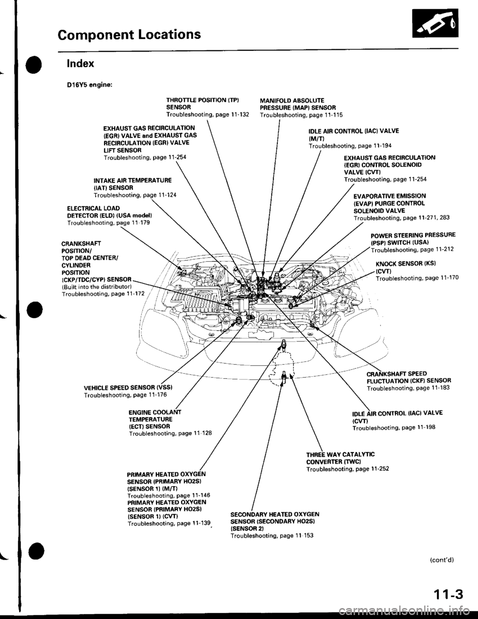
Gomponent Locations
L
lndex
D16Y5 engine:
{IATISENSORTroubleshooting,
ELECTRICAL LOADDETECTOR IELD) (USA mod6l)Troubleshooting, page 11 179
THROTTLE POSITION ITP)SENSORTroubleshooting, page 1 1-132
MANIFOLD ABSOLUTEPRESSURE IMAPI SENSORTroubleshooting, page 1'l-115
EXHAUST GAS RECIRCULATION
IEGRI VALVE and EXHAUST GAS
RECIRCULATION IEGRI VALVE
LIFT SENSORTroubleshooting, page'l 1-254
INTAKE AIR TEMPERATUR€
IDLE AIR CONTROL (IAC) VALVE
{M/T)Troubleshooting, page 1 1-194
EXHAUST GAS RECIRCULATION{EGRI CONTROL SOLENOIDVALVE ICW)Troubleshooting. page 1 1-254
EVAPORATIVE EMISSIONIEVAPI PUNGE CONTROLSOLENOID VALVETroubf eshooting, Page 1 1'21 1, 243
CRANKSHAFTPOS|TTON/TOP DEAD CENTER/CYLINDERPOS|T|ON
POWER STEERING PRESSURE(PSP) SWITCH (USAI
Troubleshooting, Page 1 1-212
KNoCK SENSoR (Ks)
(cwl
Troubleshooting, Page 1 1'170ICKP/TDC/CYP} SENSOR(Built into the distributor)Troubleshooting, Page 1 1'172
VEHICLE SPEED SENSORTroubleshooting, Page 1 1-176
FLUCTUATION (CKF} SENSOR
Troubleshooting, Page 1 1 -183
ENGINE COOLANTTEMPERATUREIECT) SENSORTroubleshooting, Page 11 128
IDT.ECONTROL IIACI VALVE
{cw)Troubleshooting, Page 11 198
WAY CATALYTICCONVERTER ITWCITroubleshooting, Page 1 1-252PRIMARY TIEATEDSENSOR {PNIMARY HO2SI
tsENsoR 1t {M/TlTroubleshooting, Page'l 1-146
PRIMARY HEATED OXYGENSENSOR (PRIMARY HO2SI
tsENsoR 1l {cw}Troubleshooting, Page 1 1-139
SECONDARY HEATED OXYGENSENSOR {SECONDARY HO2S){SENSOR 2)Troubleshooting, page 11 153
(cont'd)
1 1-3
Page 276 of 2189
I
CLUTCH SWITCH lDl6Y5 onginoM,/TITroubleshooting, page 1 1-218
'96 - 98 modsls:
Sell-diagnostic Procedures.page 11 81
ENGINC CONTROL MOOUI.T(FCMI/POWERTRATN
CONTROL MODULE IPCMITroubleshooting, page 1 1-107
'9!, - 0o modol3:
PGM.FI MAIN RELAYRslay Testing, page 11-237Troubleshooting, page 1 1-238PGM.FI MAIN RELAYRelay Testing, page l1 237Troubleshooting, pago 1'! 238
SERVICEl2Pl
CONNECTOR
ENGINE CONTROL MODU1T(ECM}/POWERTRAIN
CONTROL MODULE IPCMITroubleshooting, page 11 111SERVICE CHECK CONNECTORtzPlSelf-diagnostic Procedures,page 11-81
Self-diagnostic Procedures,page 11-81
{cont'd)
11-7
Page 302 of 2189
PSP SWITCHI
c1t7
atu/wHT =..'-_/YEL Jlr.^r'\-r IwHr---] FaMrr=ll
L_id-ll8r-x,--L- |
CAI\IISTER VENT
tr--+r-*' I=
calT_ 66s' fr:-ll-BL!(--- - lf.a - ICLUTCH SWTCH'X_-o_
I(cont'd)
1 1-33
IT GRN/WI{T
ctor
Page 309 of 2189
System Description
Electrical Connections ('99 - 00 Models except Dl6Y5 engine with M/Tl
(cont'd)
T:I
1
0
EVAP PURGE CONTROLSoLENOtOVAIVEc26 ECTECTSENSOR
D
EVAP COI{TROL CANISIE R
IATSENSOR
ta-t
c25 tAT
HO2S(sENSoFt
EVAP BYPASS SOI.ENOID VALVE
cl Po2s{tc"Eso! 87
)wEGF coNTRoL solENoro vaLvE'"c16PHO2S
vlsBr2VTEC SOLEr{O|D VATVE
H02SiSENSOR 2),wA23 SHO2S
VTECPFESSUFESWITCH
sEt{soR
-t,.1 f
I
BRAKE SWITCH
c7 sG1
SENSOB(Buln l oF
@E
lfil
*_r
/V | GAUGE
* lassEMBLIIl-
SPEEOSENSOR
tr
D5VBSOLo4tND A14
N DTI
NC DTOSPEEDSENSOR
LS+ Bl7UNEAR SOLENOID VALVET'I AT?04LS- a3
LOCIPr. l03alP03LCA 01P CONTBOISOIENOiDVALVE BLCB 03IOI{IROL SOLENOID VAIV€ A
SHIFI COTITROL SOLENOID VALVE BSHE D2
POStTtON
t----
I
To IIIT!FLOCK CONTROL UNIT
--t
L
l-
I
I
11-40
-.._.._.._.._l
,'-J
Page 317 of 2189
System Description
Electrical Connections ('99 - 00 Models except Dl6Y5 engine with M/Tl
(cont'dl
DRIVE PULIEY SPEEO SENSOF
SECONDAFY GEAFSHAFT SPEEO SENSOR
SCLSM
INHSOL
PNK/BLK
YE!'
PNK/BIU
cnvauC
c131 CrKa
GFN/Brf I f cnvsuCL_
,T GEAF POSII|ON SWITCH
11-48
Page 350 of 2189

Troubleshooting
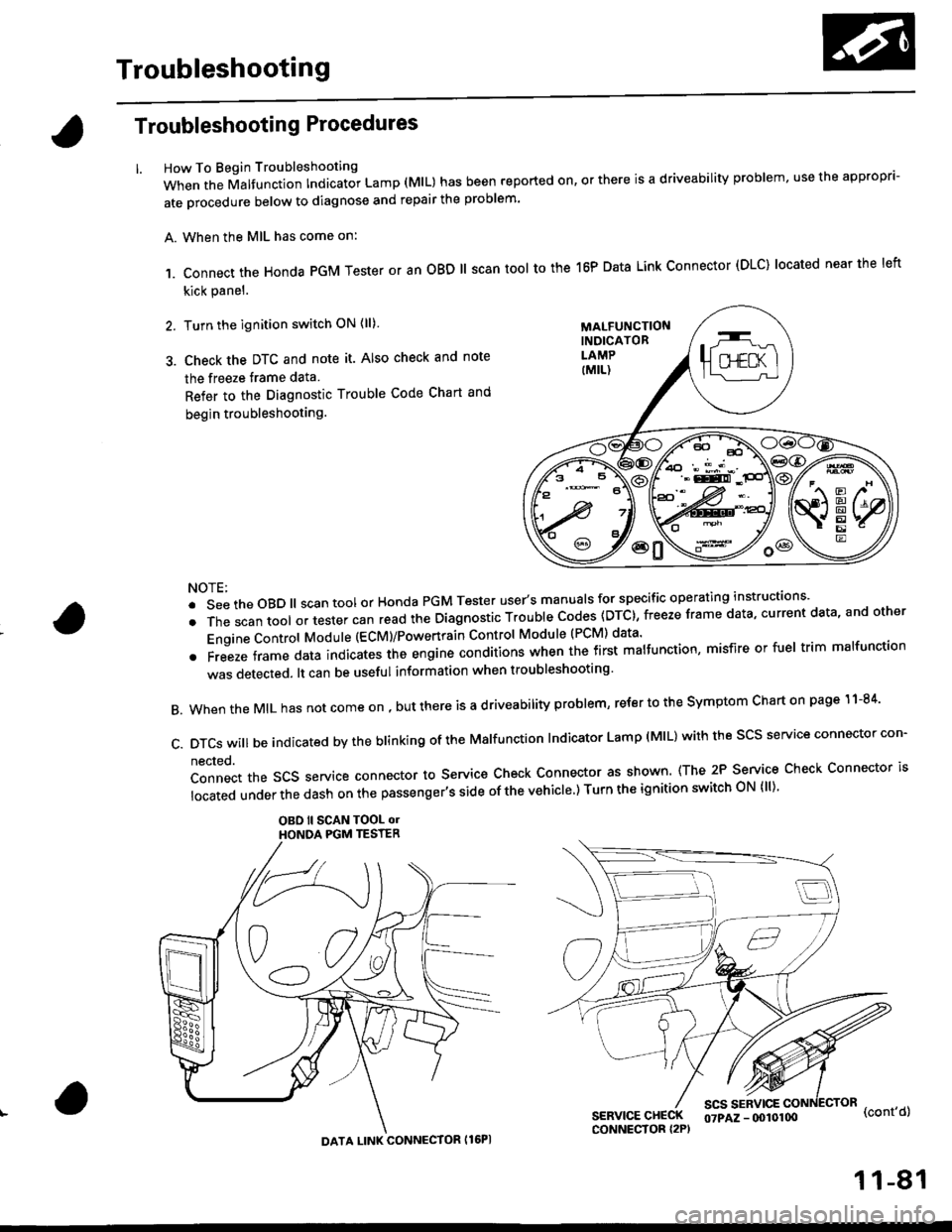
Troubleshooting Procedures
How To Begin Troubleshooting
When the Malfunction Indicator Lamp (MlL) has been reported on, or there is a driveability problem, use the appropr'-
ate orocedure below to diagnose and repair the problem'
A. When the MIL has come on:
,1. connect the Honda PGM Tester or an oBD ll scan tool to the 16P Data Link connector (DLC) located near the left
kick panel.
2. Turn the ignition switch ON (ll)
3. Check the DTC and note it. Also check and note
the freeze trame data
Refer to the Diagnostic Trouble Code Chart and
begin troubleshooting.
NOTE:
.SeetheoBD||scantoolorHondaPGMTesteruser,smanua|sforspecificoperatinginstructions..
.Thescantoo|oltestercanreadtheDiagnosticTroub|ecodes(DTc},freezeframedata,currentdata,andother
Engine Control Module (ECM)/Powertrain Control Module (PCM) data'
oFreezeframedataindicatestheengineconditionswhenthefirstma|function,misfireorfue|trimma|function
was detected. lt can be useful information when troubleshooting'
B. When the MIL has not come on , out there is a d riveability problem, refer to the Symptom Chart on page 1 1-84'
c.DTcswi|lbeindicatedbytheb|inkingoftheMa|function|ndicatorLamp(M|L)withthescsserviceconnectorcon.
nected.
Connect the SCS service connector to Service Check Connector as shown (The 2P Service Check Connector is
|ocatedunderthedashonthepassenger,ssideofthevehic|e')TurntheignitionswitchoN{||)'
OBO ll SCAN TOOL olHONOA PGM TESTER
SERVICE CHECKCONNECTOR I2P)
scs sERvlcE(cont'd)
MALFUNCTIONINDICATORLAMP
DATA LINK CONNECTOR Il6PI
07PAZ - (x)l0100
11-81