Page 1434 of 2189
Troubleshooting
Condenser Fan (cont'd)
CONDENSER FAN RELAY 4P SOCKET
CONDENSEB FAN 2P CONNECTORWire side of female terminals
-=F_
l!.lI slx
@I
Check tor an opon in the wi.o:1. Disconnect the jumper wire.2. oisconnect the condenser tan2P connector.3. Check for continuity betweenthe No. 1 terminal of the con-denser fan relay 4P socket andthe No. 1 terminal of the con-denser fan 2P connector.
Rapair op6n in the wirs bgtwconthe condcnsor tan rclay and thecondgnlar fan.
ls there continuity?
Check to. en open in the wire:Check for continuity between theNo. 2 terminal ot the condenserfan 2P connector and bodyground.
Check Ior rn opon in th6 wirebctwoen the condcnser tan andbody ground, lf iho wirc ii OK,chcck for poor ground at G751.
ls there continuity?
Replaco the condense. fan motor.
22-10
Page 1439 of 2189
Frcm page 22-14
Check lor an open in the wire:1. Turn the ignition switch OFF.
2. Disconnect the A/C pressure
switch 2P connector.3. Turn th ignition switch ON lll).4. Measure the voltage between
the No. 1 terminal of the AJCpressure switch 2P conneclorand body ground.
Check the A/C pressure switch:1. Turn the ignition switch OFF.
2. Check for continuity between
the No. 1 and No. 2 terminalsof the Ay'C pressure switch.
ls there continuity?
Check for A/C system ptessure.
ls the pressure within sPeci_f cations?Repair the A/C pressure Problem
A/C PRESSURE SWITCH 2P CONNECTOR
ls there battery voltage?
wire side of {emale terminals
A/C PRESSURE SWITCH
Repair open in the wire between
the condenser fan relay tnd the
A/C oressure switch.
1o page 22-16
(cont'd)
22-15
Page 1441 of 2189
A/C System
CONDENSER FAN RELAY 4P SOCKET
A/C system does not come on
{comDressor and fan).
Check the No. 56 fuse in theunder'hood fuse/relay box andthe No. 17 fuse in the under-dashfuse/relay box.
ReDlace the fus6{s}, and recheck.
Check for tn open in the wire:
1. Remove the condenser lanrelay from the u nderhood
luse/relay box.2. Turn the ignition switch ON {lli.3- Measure the voltage betweenthe No. 4 terminal of the condenser fan relav 4P socketand body ground.
Repair open in the wire between
the No. 17 fuse and the con-denser fan r6lay,
Check the under-hood fus€/r6laybox:Measure the voltage between the
No. 2 terminal of the condenser
fan relay 4P socket and bodyground,
YES
Io page 22-18
(cont'd)
Page 1445 of 2189

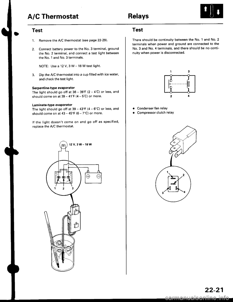
A/C ThermostatRelays
Test
1.Remove the Ay'C thermostat (see page 22-29).
Connect baftery power to the No. 3 terminal, ground
the No. 2 terminal, and connect a test light between
the No. 1 and No. 3 terminals.
NOTEr Use a 12 V,3 W- l8 W test light.
Dip the IVC thermostat into a cup filled with ice water,
and check the test light.
Serp6ntine-type evaporator
The light should go off at 36 - 39'F {2 - 4"C} or less, and
should come on at 39 - 41"F (4 - 5"C) or more
Laminale-type evaporator
The light should go off at 39 - 43'F (4 - 6'C) or less, and
should come on at 43 - 45"F (6 - 7'C) or more
lf the light doesn't come on and go off as specified,
replace the PVC thermostat.
12V,3W-18W
Test
There should be continuity between the No, 1 and No.2
terminals when power and ground are connected to the
No.3 and No. 4 terminals, and there should be no conti-
nuitv when Dower is disconnected.
2
Condenser fan relay
Compressor clutch relay
a
a
,I Ib
In Io'r I
t\----,'
t:n
,,l[4..-.
22-21
Page 1471 of 2189

l'f .
Electrical
Special Toofs .,....................,23-2
Troubleshooting
Tips and Precautions ..............,.................... . 23-3
Five-step Troubleshooting .............. ......... . . 23-5
wire color codes ..........,23-5
Schematic Symbols ........,................... . . .. .... 23-6
Relay and Control Unit Locations
Engine Compartment ...,..................... ... .. . 23'7
Dashboard ......................23-8
Dashboard/Door ......... 23-12*Airbags ................. ....... Section 24
Air Conditioning ......... Section 21
Aftelnator ..........."""" """ 23-112
Anti-lock Brake System {ABS) Section 19*A/T Gear Position Indicator .....................,. .... ... 23-149
Automatic Transmission Svstem .... . ....... Section 14
Batterv ......... . . . ... ...... .......23-91
Blower controls .. . ... Section 2l
Charging System ....'...........23'112
Connector ldentilication and Wire Harness
Routing .................. ......23'13
Cruise Control ............,........23-240
Dash Lights Brightness Controller ............. ....... 23-180
Fan controfs "" 23'126
Fuel PumD ........ . ........ section 11
Fuses/Refay ...............,..,,.. 23'62
PGM-FI Control System ......................,....... Section 1 1
*Gauges
Circuit Diagram ....,.,.......23-131
Fuef Gauge ...........'.'.......23-142
Gauge/lndicator .. . .. 23-129
Ground Distribution .. . 23-75
Heatei controls .. . ..... Section 21*Horn................. ...............23-196
*tgnition Switch ....................23-89
lgnition System .......,.... 23-102
*lntegrated Control Unit ....................................... 23-156
fnterlock System ,........ . . , ,23-144
Lighting System . . . .. ......... 23-161
Lights, Exterior
Back-up Lights ..'............23'171
Brake Lights .................. 23'174
Daytime Bunning Lights (Canadal ............... 23'166
Front Parking Lights ......,................ .'. .......... 23-167
Front Turn Signal Lights .......... . . ............ ..,.23-167
Headtights ....".'....-... ..... 23'167
High Mount Brake Light ...................... ... .23'179
License Plate Lights ...... 23'176
Taitfights ................ .......23'171
lnterior Lights ..-.......,, . 23-142
Moonroof ..,.................,........ 23-235
Power Distribution ....... . . .23-61
Power Door Locks .......,,,. .23'251
Power Mirrors ,..............,.,...23'206
Power Relays ....... . ...... . . .. 23-86
Power Windows ............,,....23-220
Rear Window Defogger .......................... . . ... . . 23-2OO
Spark Plugs . ..... . ........ .....23-111
Slarting System ................23-93*stereo Sound Svstem ,................. ..... ... . ... ,.,.,,23'147'Supplemental Restraint System (SRS) ... . Section 24
Turn Signal/Hazard Flasher System .......'.'....-... 23-173
*Undel-dash Fuse/Relay Box ............,.................. 23-85
vehicfe soeed sensor (VSSI """" ""' 23-140+Wipers/Washers .........,.,.,...23-214
NOTE: Unless otherwise specified, references to auto-
matic transmission (Mf) in this section include the CVT.
Page 1477 of 2189
Relay and Control Unit Locations
Engine Compartment
UNDER.HOOD ABS
FUSE/RELAY BOX
CONDENSER FAN
RELAY
UNDER.HOODFUSE/RELAY BOX
MOTORRELAY
A/C COMPRESSORCLUTCH RELAY
RADIATORFAN RELAY
ELD UNIT
t:
tr
tr
uI Il I tl I
23-7
Page 1484 of 2189

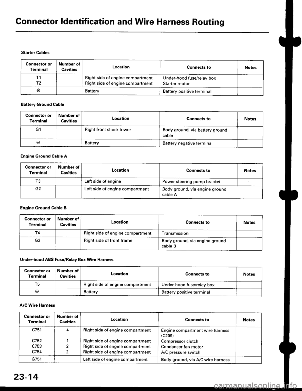
Connector ldentification and Wire Harness Routing
Connector or
Terminal
Number of
CavitiesLocalionConnec{s toNotes
T,I
r2
Right side of engine compartment
Right side of engine compartment
Under-hood fuse/relay box
Starter motor
BatteryBattery positive terminal
Starter Cables
A/C Wire Harness
Battery Ground Cable
Connector or
Terminal
Number of
CavitiesLocationConn€cts toNotos
Right front shock towerBody ground, via battery ground
caDte
oBafteryBattery negative terminal
Engine Ground Cable A
Conn€qtor or
Terminal
Number ot
CavitiosLocationConnects toNoles
T3Left side of enginePower steering pump bracket
G2Left side of engine compartmentBody ground, via engine ground
cable A
Engine Ground Cable B
Connector or
Terminal
Number of
CavitiesLocationConnecls toNoles
T4Right side of engine compartmentTransmission
Right side of front frameBody ground, via engine ground
cable B
Under-hood ABS Fusa/Relay Box Wire Harness
Connector or
Tgrminal
Number oI
CavitiesLocationConneqts toNotes
T5Right side of engine compartmentUnder-hood fuse/relay box
@BaneryBattery positive terminal
Connector or
Terminal
Number of
CavitiesLocationConnects toNotes
c753
c754
1
2
Right side of engine compartment
Right side of engine compartment
Right side of engine compartment
Right side of engine compartment
Engine compartment wire harness(c209)
Compressor clutch
Condenser fan motor
A,/C pressure switch
Left side of engine compartmentBody ground, via A,/C wire harness
23-14
Page 1532 of 2189
Fuses
Under-hood Fuse/Relay Box
cgo1lTo condensor fan relayl
Gr02lTo blower motor r€layl
c903*: Not usod
NOTE; View from the backside of the under-hood fuse/relav box.
[To radi.lor tan rolayl
cto5[To main wir6 harne$ (C3521]
fto l/c comprdssor]
lclutch relay I
c905lTo main wire ha.ness (C353ll
DE
tr
tr
tr
r-1
IJ
r"l17LI
n51
IJ
r"l56
LI
r"l57IJ
23-62
ITo main w;re ha.ness (C351ll