Page 1331 of 2189
Hatch Spoiler
Removal
NOTE: Take care not to scratch the hatch and body
1. Remove the hatch upper trim (see page 20-63)
2. Remove the nuts, and detach the clip, then lift the
hatch spoiler uP.
a: Nut locations, 4
1 2lbt.ftl _ j/
GROMMET
HIGH MOUNT BRAKELIGHT CONNECTOR
Disconnect the high mount brake light connector and
rear window washer tube, then remove the hatch
spoiler.
------,*;)
4. lf necessary. remove the spoiler trim from the spoiler
frame.
NOTE: The hatch spoiler trim for Canada produced
cars cannot be disassembled.
>: Clip locations
A>,4
>: Scr€w
5. Installation is the reverse of the removal procedure'
NOTEi
. lf necessary, replace any damaged clips.
a Make sure the connector and washer tube are
connected ProPerlY.
20-101
Page 1334 of 2189

Door and Side Moldings
Replacement (cont'dl
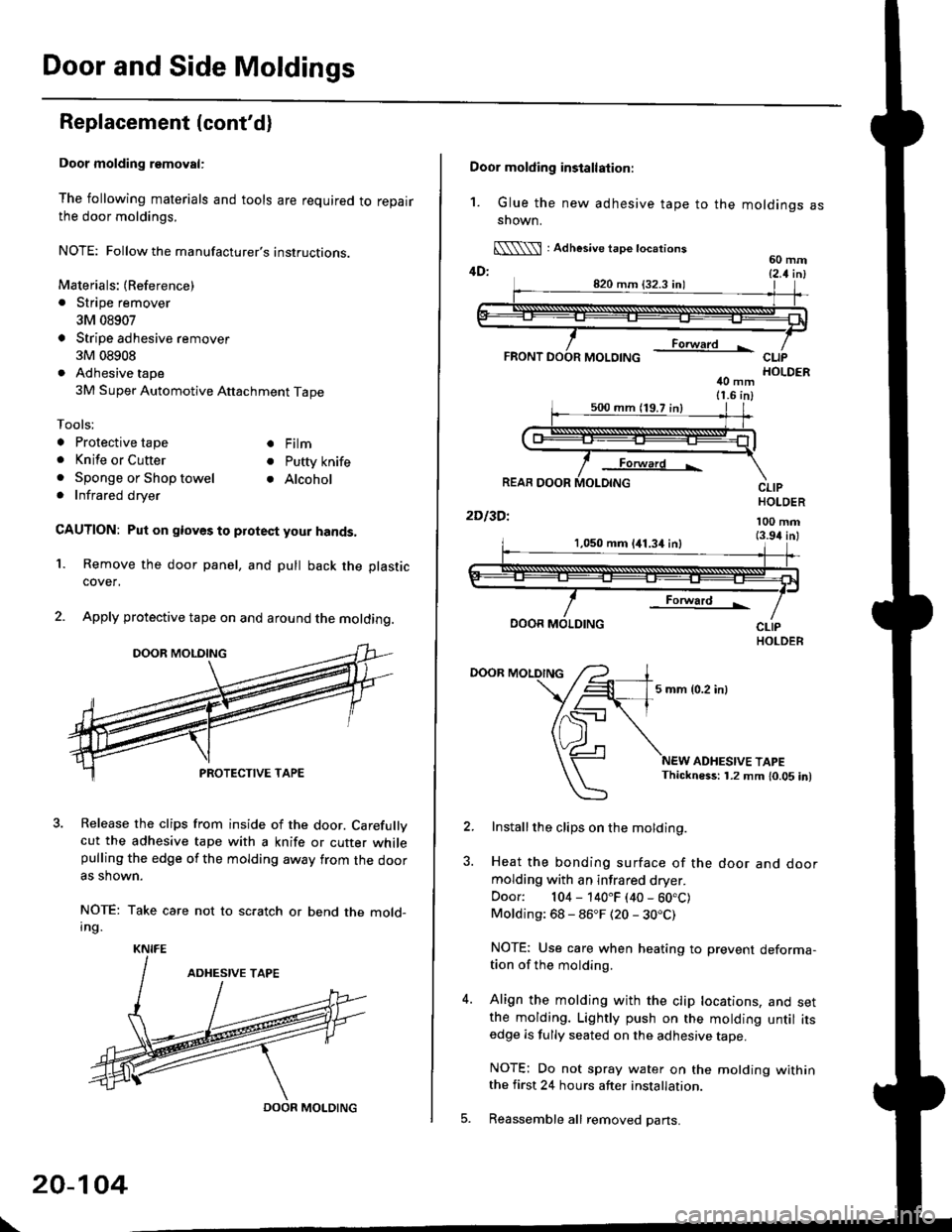
Door molding removal:
The following materials and tools are required to repairthe door moldings.
NOTE: Followthe manufacturer's instructions.
Materials: (Reference)
. Stripe remover
3M 08907
Stripe adhesive remover
3M 08908
Adhesive tape
3M Super Automotive Attachment Tape
Tools;
a Protective tape
. Knife or Cutter
. Sponge or Shop towel. Infrared dryer
. Film
. Putty knife
. Alcohol
CAUTION: Put on gloves to protect your hands,
Remove the door panel, and pull back the plastic
cover,
Apply protective tape on and around the molding.
3. Release the clips from inside of the door. Carefullvcut the adhesive tape with a knife or cutter whilepulling the edge of the molding away trom the dooras shown.
NOTE: Take care not to scratch or bend the mold-Ing.
1.
KNIFE
DOOR MOLDING
\
20-104
Door molding installation:
1. Glue the new adhesive tape to the moldings assnown.
[\\\l : Adhesive tape tocations60 mm4D: t2 t i^l
40 mm11.6 in)
Forward L
REAR DOOR
2Dl3Dl
CLIPHOLDER
100 mm(3.94 inl1,050 mm 141.34 inl
Forward !
DOOR MOLDING
DOOR MOLDING
5 mm {0.2 inl
ADHESIVE TAPEThickness: 1.2 mm 10.05 in)
Installthe clips on the molding.
Heat the bonding surface of the door and doormolding with an infrared dryer.
Door: 104 - 140"F (40 - 60.C)Molding: 68 - 86"F (20 - 30.C)
NOTE: Use care when heating to prevent deforma-tion of the molding.
Align the molding with the clip locations, and setthe molding. Lightly push on the molding until itsedge is fully seated on the adhesive tape.
NOTE: Do not spray water on the motding withinthe first 24 hours after installation.
Reassemble all removed pans.
Page 1369 of 2189
Emblems
Installation
Align the application tape with the taillight and body, as shown, then press the emblem into place. Remove the appticationtape.
NOTE:
o Before applying, clean the body surface with a sponge dampened in alcohol.. After cleaning, keep oil, grease and water from getting on the surface.. When applying, make sure there are no wrinkles in the emblem.
Attschment Point:
VERSION EMBLEM
20-140
DOHC VTEC aid€ omblom:Vsrsion emblem:
Page 1378 of 2189
Circuit Diagram
'96 - 98 Models
LINDEF NoOD FUSETFELAY 30x
WNTTBLK +WFT
8L|(YEi
LIGHT
Y
I
No1l lS0Al Ni42 (40A)
S;rt' | | lieti{,**i'-t L-:} [:] | h
crca(.-A-o \1 \-r. \-r-1 \'\
!9[1' ? _?__?'? _t__?__t
21-4
Page 1379 of 2189
'99 - 00 Models
UNDER,HOOO FUSE/RELAY 8OX
PUSN SWITCH
lHce nvosrar F)- aLu neo(Wirh IVC)
DASH LIGHTS -/1BBTGNTNESS < l- FEoCONTROLLER -!
IGN TION SW TCHUNDEF DASHFUSElRELAY BOX
**,',,* **",@ ",.
@f
u,n,",,
ELUAVHT
I
YBLUi BtK
BLOWERMOTOR
ELOWERMOTORHIGHRELAY
PNK/BLK
FED''WHT
RED,YEL
GRY
BRN
YEL
YEL/FEO
6RNiYEL
8LU/!VHT
YEL/BLU
BRNfiHT
GFNM/HT
GRNi FED
O :8P CONNECTOR
! :20P CONNECTOF
E : 12P CONNECToR
BLUi BLK
1
tic
HEATER CONTROL PANEL
VENT
MOOEHEAT CONTFOLMOTOF- M.COMDEF
[[f&H,,4*,",,
BLK
Page 1381 of 2189
Heater Control Panel Input/Output Signals
HEATER CONTROL PANEL lilP CONNECToR
Wire side of lemale terminals
21-7
Terminal
No.
Wire
colorSignalTerminal
No.
Wire
colorSignal
1YELHEAT/DEFINPUT8YEVREDVENTINPUT
BLfiELINPUT9G RNI/ELHEATIr'ENTINPUT
WHT/BLU+BINPUT'10BLKGROUNDOUTPUT
4YEUBLUDEFINPUT11*BLU/REDA./C THERMOSTATINPUT
5REDDASH LIGHTS
BRIGHTNESS CONTROLLEROUTPUT12GRN/WHTFRESHINPUT
6RE D/8LKCOMBINATION LIGHT
SWITCHINPUT13GRN/REDRECIRCULATEINPUT
1BLUMHTHEATINPUT14GRNHEATER FAN SWITCHOUTPUT
Page 1394 of 2189

Troubleshooting -'99 - 00 Models
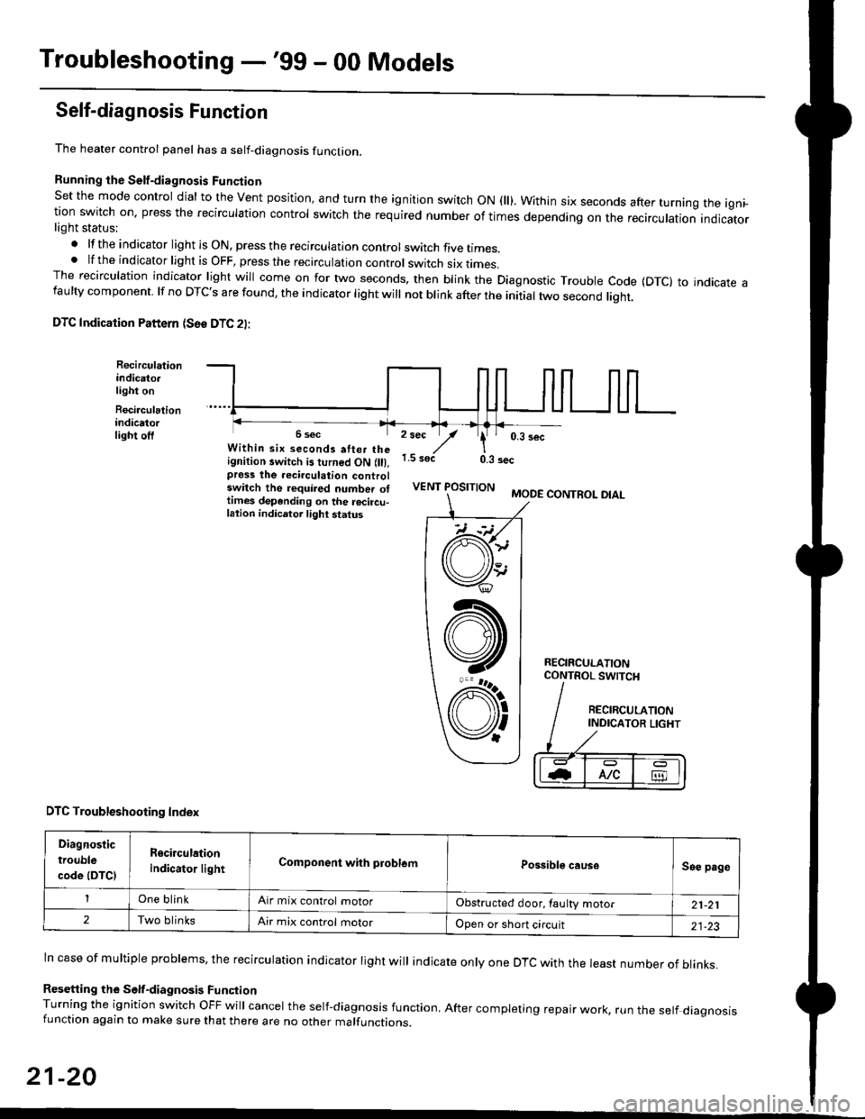
Self-diagnosis Function
The heater control panel has a self-diagnosis function.
Running the Self-diagnosis Funqtion
Set the mode control dial to the Vent position, and turn the ignition switch ON fll). Within six seconds after turnang the igni_tion switch on. press the recirculation control switch the required number of times depending on the recirculation indicatorlight status:
.lftheindicatorlightisON,presstherecirculationcontrolswitchfivetrmes.
.lftheindicatorlightisOFF,presstherecirculationcontrol switch six rrmes.The recirculation indicator light will come on for two seconds. then blink the Diagnostic Trouble code {DTc} to indicate afaulty component. lf no DTc's are found, the indicator light will not blink after the initial two second liqht.
DTC Indication Pattern (S6e DTC 2l:
Recirculationindicato.light on
Recirculationindicatorlight off2 sec
,/1.5 soct
' 0,3 secWithin six seconds atter theignition switch is turned ON (lll,pross the recirculation controlswitch the required number ottimes depending on the rocircu-lation indicetor light status
0.3 sec
VENT POSITIONMODE CONTROL DIAL
RECIRCULATIONCONTROL SWTCH
DTC Troubleshooting Index
Diagnostic
trouble
code (DTCI
Rgcirculation
indicator lightComponent with problemPossible causeSee page
One blinkAir mix control motorObstructed door, laulty motor21-21
2Two blinksAir mix control motorOpen or short circuit21-23
ln case of multiple problems, the recirculation indicator light will indicate only one DTc with the least number of blinks.
Resetting the Self-diagnosis FunctionTurning the ignition switch OFF will cancel the self-diagnosis function, After completing repair work, run the setf diagnosisfunction again to make sure that there are no other malfunctions.
21-20
@
At
V'
Page 1395 of 2189

Air Mix Gontrol Motor
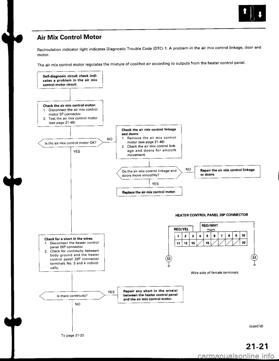
Recirculation indicator light indicates Diagnostic Trouble code (DTC) 1l A problem in the air mix control linkage, door and
motor.
The air mix control motor regulates the mixture of cool/hot air according to outputs from the heater control panel'
Self-diagnosis circuit check indi'
cates a Problem in the air mix
conlrol motor circuit,
Check th6 aii mix conirol motor:
1. Disconnect the air mix control
motor 5P connector.
2. Test the air mix control motor(see page 21-46).
check the air mix control linkage
and doors:1. Remove the air mix control
motor (see Page 21-46)
2. Check the air mix control link-
age and doors lor smooth
movement.
ls the air mix control motor OK?
Do the air mix control linkage and
doors move smoolhlY?
R€olace the air mix control motor'
Check tor a short in the wiles:
1. Disconnect the heater controlpanel 20P connector-2. Check for continuitY between
body ground and the heater
control panel 20P connector
terminals No.3 and 4 individ'
uaIY.
Ropair any short in th€ wire{s}
betweon the heater control Paneland the air mix control motor'
HEATER CONTROL PANEL 2OP CONNECTOR
RED/WHTRED/YEL
Wire side ot female terminals
(cont'd)
fo page 21-22
21-21