Page 1226 of 2189
lgnition Voltage
Diagnostic Trouble Code (DTC) 61: lgnhion Voltage Diagno3is
A8S CONTROL UNIT 26P CONNECTOR
IG2IBLK/BLU}
]Wire side of lemale terminals
- With tha engin€ running, ABSindicator lighl is ON.- With the SCS s€rvice connec-to. conn€ctod ls€€ page 19-561,DTC 61 is indicated.
Problem v€rification:1. Erase the DTC.2. Start the engine.3. Make sure that the ABS ind;cator light comes on and DTC61 is indicated.
ls DTC 61 indicated?The system b OK .t this time.
Check the lG2 cilcuii:Measure the voltage between theABS control unit 26P connectorterminal No. 3 and body ground.
ls there 18 V or above?
lf the vohage is 0 V, check lor anopon in the lG2 circuit.It there is 12 - 17 V. substitute aknown-good ABS colrtrol unit andJecheck.
It
19-73
Page 1227 of 2189
Troubleshooting
Central Processing Unit (CPUI
Diagnostic Troublo Code IDTC) 81: CPU Disgnosis
- With the ignition switch ON{lll. ABS indicator light doesnot go oft.- With tho SCS servi@ connec-tor conn€cted lsee page 19{6},DTC 81 is indicated.
P.oblem vedfication:1. Erase the DTC.2. Test-drive the vehicle.3. Make sure that the ABS indi,cator light comes on and DTC81 is indicated.
ls DTC 81 indicated?R€pllc6 th. ABS control unh.
The system k OK rt this time.
19-74
Page 1228 of 2189
\il
Modulator Unit
RemovaUlnstallation
CAUTION:
. Do not spill brake tluid on the car; it may damage the paint; it brako lluid does contact the paint, wash it off immedi-
ately with wator.
a Take care not to damage or delorm the brake lin€s during removal and installation.
. To prevent the brake tluid from tlowing, plug and cover the hose €nds and ioints with a shop tow6l or equivalent
mat€rial.
NOTE| Tightentheflare nutsto 15 N.m (1.5 kgnm. l1 lbf.ft).
Removal
'1. Disconnect the modulator unit 10P and Dump motor 2P connectors.
2. Disconnect the brake lines, then remove the modulator unit.
Installaiion
1. Install the modulator unit. then connect the brake lines.
2. Connect the modulator unit 10P and oumD motor 2P connectors.
3. Bleed the brake system.
4. Start the engine, and check that the ABS indicator light goes off.
Fomright-1461
PUMP MOTOR2P CONNECTOR
J
-R
/2e'
t'
TOR UNIT
tt
19-75
Page 1253 of 2189
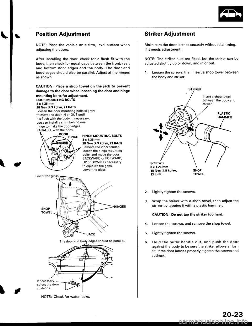
bPosition Adjustment
NOTE: Place the vehicle on a firm, level surface when
adjusting the doors.
After installing the door, check for a flush fit with the
body, then check for equal gaps between the front, rear,
and bottom door edges and the body. The door and
body edges should also be parallel. Adjust at the hinges
as shown,
CAUTION: Place a shop towel on the iack to prevent
damage to the door when loosening the door and hinge
mounting bohs for adiustment.
DOOR MOUNTING BOLTS8 x 1.25 mm28 N.m {2.9 kgf.m.21 lbt'ft}Loosen the door mounting bolts slightly
to move the door lN or OUT until
it's flush with the body. lf necessary,
vou can installa shim behind one
hinge to make the door edgesPARALLEL with the body.
J
HINGE MOUNTING BOLTSI x 1.25 mm28 N.m (2.9 kgf.m,21 lbtft)Remove the inner fender,loosen the hinge mountingbolts, and move the doorBACKWARD or FORWARD,UP or DOWN as necessaryto equalize the gaps.Lower the glass.
\
The door and body edges should be parallel-
ifF t
NOTE: Check for water leaks.
20-23
Striker Adjustment
lvlake sure the door latches securely without slamming.
lf it needs adjustment:
NOTE; The striker nuts are fixed, but the striker can be
adjusted slightly up or down, and in or out.
'L Loosen the screws, then insert a shop towel between
the body and striker.
Insert a shop towelbetween the body and
sc8Ews8 x 1.25 mm18 N.m (1.8 kgf.m,13 tbtftl
PLASTIC
2. Lightly tighten the screws.
3. Wrap the striker with a shop towel, then adjust the
striker by tapping it with a plastic hammer.
CAUTION: Do not tap the striker too hard.
4. Loosen the screws. and remove the shop towel.
Lightly tighten the screws.
Hold the outer handle out, and push the door
against the body to be sure the striker allows a flush
fit. lf the door latches properly, tighten the screws and
recheck.
5.
Page 1260 of 2189
Windshield
Installation (cont'd)
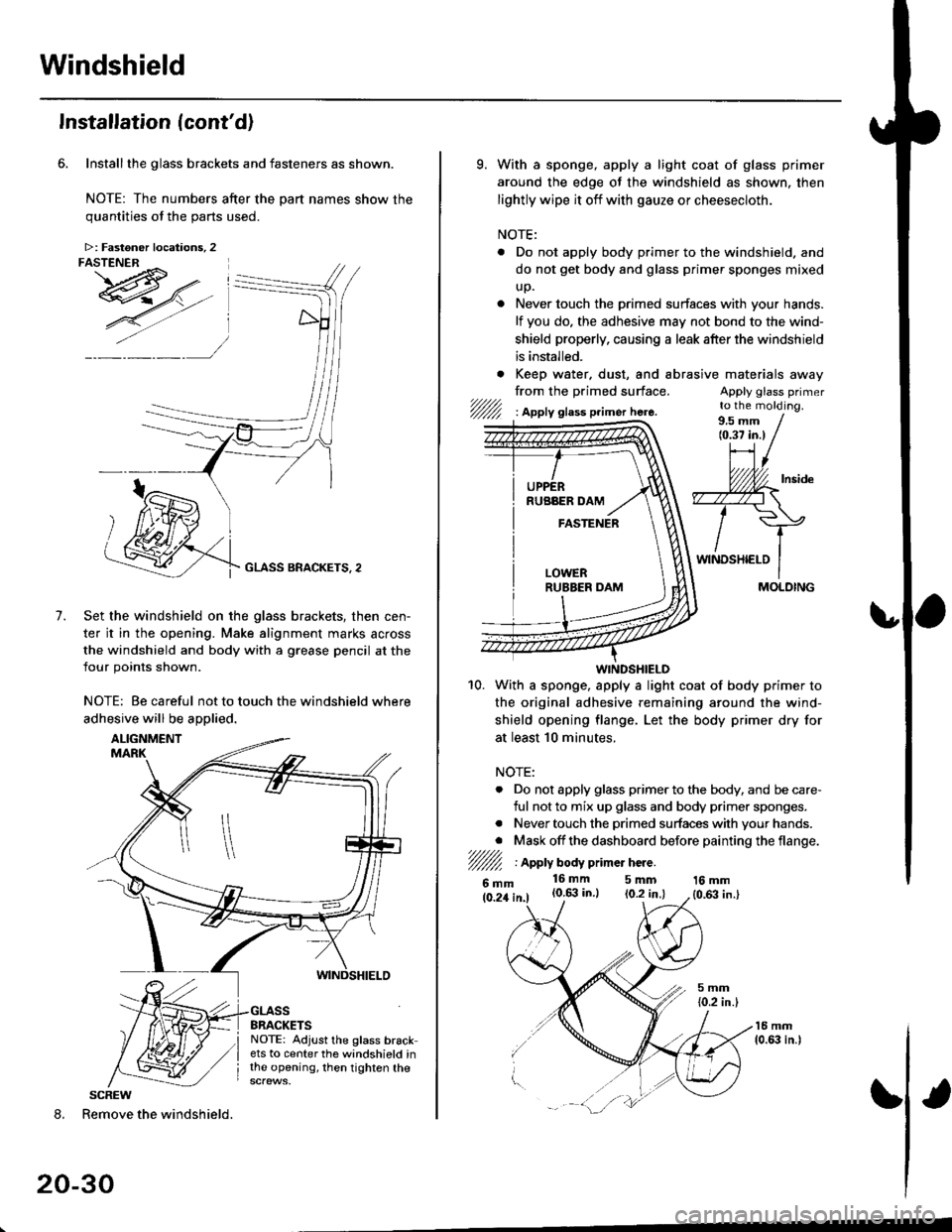
Installthe glass brackets and fasteners as shown.
NOTE: The numbers after the part names show thequantities of the oarts used.
GLASS BRACKETS, 2
Set the windshield on the glass brackets, then cen-
ter it in the opening. Make alignment marks across
the windshield and body with a grease pencil at the
four points shown.
NOTE: Be careful not to touch the windshield where
adhesive will be aDolied.
7.
8. Remove the windshield.
20-30
>: Fastoner locations, 2FASTENER ^ I
I
SCREW
9. With a sponge, apply a light coat of glass primer
around the edge of the windshield as shown. then
lightly wipe it off with gauze or cheesecloth.
NOTE:
. Do not apply body primer to the windshield. and
do not get body and glass primer sponges mixed
up.
. Never touch the primed surfaces with your hands.
lf you do. the adhesive may not bond to the wind-
shield properly, causing a leak after the windshield
is installed.
. Keep water. dust, and abrasrve
from the primed surface.t/////,'/////l I Apply glass p.imer here.
materaals away
Apply glass primerto the molding.
WINDSHIELD
10. With a sponge. apply a light coat of body primer to
the original adhesive remaining around the wind-
shield opening flange. Let the body primer dry for
at least 10 minutes.
NOTE:
. Do not apply glass primer to the body, and be care-
ful not to mix up glass and body primer sponges.
. Never touch the primed surfaces with your hands.
. Mask off the dashboard before painting the flange.7////l/////l I Apply body p mer hcre.
6mm16mm 5mm(0.6:| in.) (0.2 in.l16 mm
{0,63 in.}
/
MOLDING
Page 1261 of 2189
3
11.Thoroughly mix the adhesive and hardener together
on a glass or metal plate with a putty knife.
NOTE:
. Clean the plate with a sponge and alcohol before
mixing.
. Follow the instructions that come with the adhe-
stve.
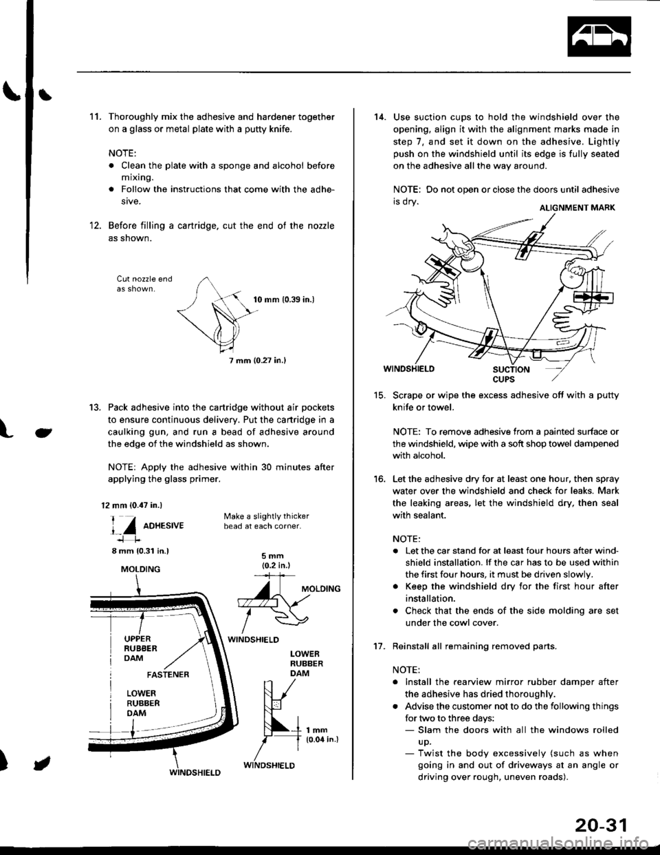
Before filling a cartridge. cut the end of the nozzle
as shown.
Cut nozzle end
tu
10 mm 10.39 in.)
7 mm (0.27 in.l
13. Pack adhesive into the cartridge without air pockets
to ensure continuous delivery. Put the cartridge in a
caulking gun, and run a bead of adhesive around
the edge of the windshield as shown.
NOTE: Apply the adhesive within 30 minutes after
applying the glass primer.
12 mm (0.47 in.)
l_Z oo*.t,ut
8 mm 10.31 in.l
UPPERRUBBERDAM
Make a slightly thickerbead at each corner.
5mm(0.2 in )='+
A\uloto^o. -.\
/wWINDSHIELD
LOWEBRUBBERDAM
lmm10.04 in.l
FASTENER
LOWERRUBBERDAM
)
MOLDING
WINDSHIELD
20-31
15.
16.
14. Use suction cups to hold the windshield over the
opening, align it with the alignment marks made in
step 7, and set it down on the adhesive. Lightly
push on the windshield until its edge is fully seated
on the adhesive all the way around.
NOTE: Do not open or close the doors until adhesive
ri vI Y ALTGNMENT MARK
Scrape or wipe the excess adhesive off with a putty
knife or towel.
NOTE: To remove adhesive from a painted surface or
the windshield, wipe with a soft shop towel dampened
with alcohol.
Let the adhesive dry for at least one hour, then spray
water over the windshield and check for leaks. Mark
the leaking areas, let the windshield dry, then seal
with sealant.
NOTE:
. Let the car stand for at least four hours after wind-
shield installation. lf the car has to be used within
the first four hours, it must be driven slowly.
. Keep the windshield dry for the first hour after
installation.
. Check that the ends of the side molding are set
under the cowl cover.
Reinstall all remaining removed parts.
NOTE:
. Install the rearview mirror rubber damper after
the adhesive has dried thoroughl',.
. Advise the customer not to do the following things
for two to three days:- Slam the doors with all the windows rolled
up.- Twist the body excessively (such as when
going in and out of driveways at an angle or
driving over rough, uneven roads).
't7.
Page 1264 of 2189
Rear Window
Installation (cont'dl
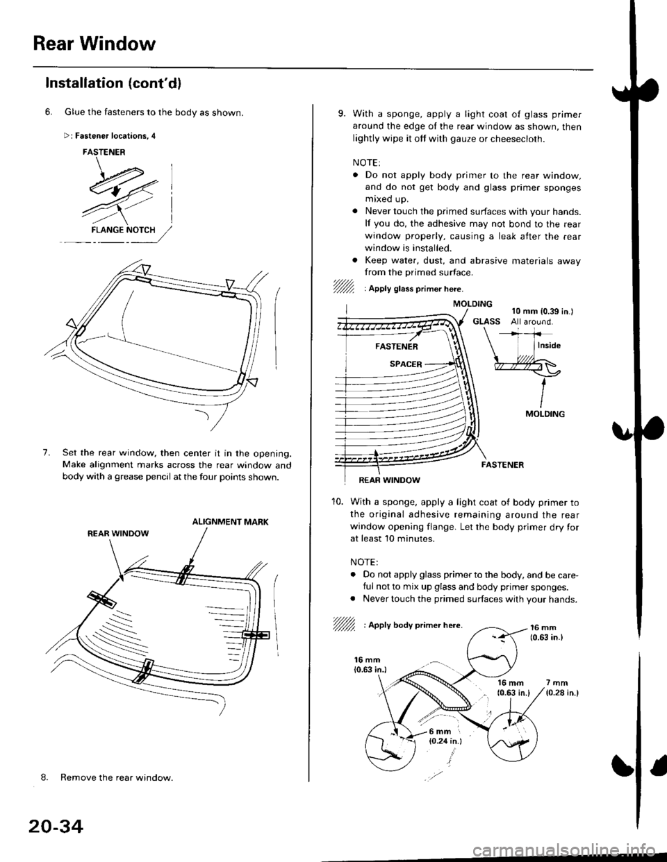
6. Glue the fasteners to the body as shown.
Fastener locations, 4
FASTENER
\-.*l-E4,7-- ,.--
7),/l
4Yl
7.
F-L NGENY:,//
Set the rear window, then center it in the opening.Make alignment marks across the rear window and
body with a grease pencll at the four points shown.
ALIGNMENT MARK
-\
-.._s
-
8. Remove the rear window.
20-34
9. With a sponge, apply a light coat o{ glass primer
around the edge oI the rear window as shown, then
lightly wipe it off with gauze or cheesecloth.
NOTE:
. Do nol apply body primer to the rear window.
and do not get body and glass primer sponges
mixed up.
. Never touch the primed surfaces with your hands.
lf you do, the adhesive may not bond to the rear
window properly, causing a leak atter the .ear
window is installed.
. Keep water, dust, and abrasive materials awayfrom the primed surface.'/fur1 : lppty gtass primer here.
16 mm(0.63 in.l7mm
{0.28 in.}
FASTENER
REAR WINDOW
10. With a sponge, apply a light coat of body primer to
the original adhesive remaining around the rear
window opening flange. Let the body primer dry for
at least 10 minutes.
NOTE:
. Do not apply glass primer to the body. and be care,
ful not to mix up glass and body primer sponges.. Never touch the primed surfaces with your hands.
/fu/ : Apply boay primer here.16 mm(0.(I, in.l
MOI-DING
l6mm r
{O.24 in.}
Page 1265 of 2189
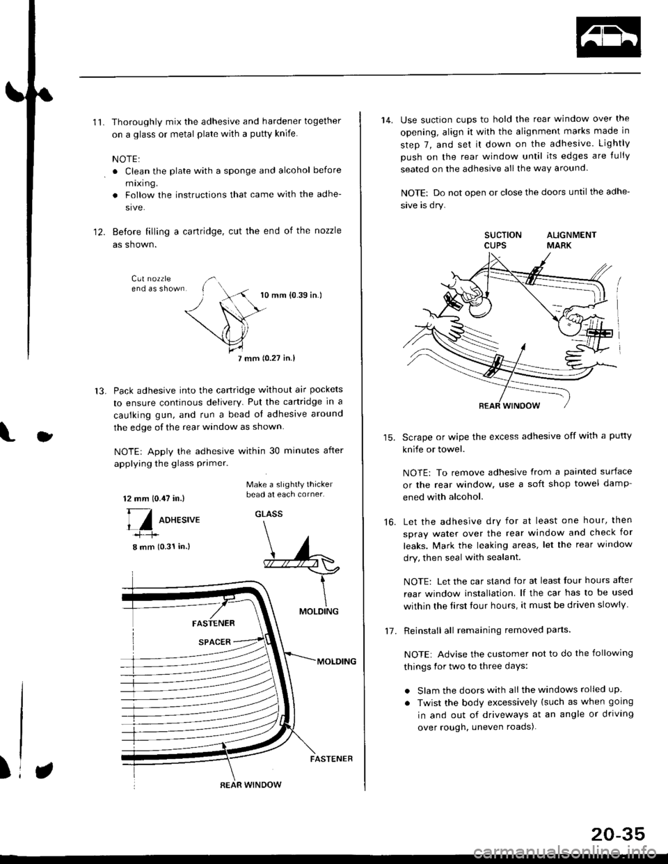
'11.Thoroughly mix the adhesive and hardener together
on a glass or metal plate wilh a putty knife.
NOTE:
. Clean the plate with a sponge and alcohol before
mixing.
. Follow the instructions that came with the adhe-
sive.
Before filling a cartridge, cut the end of the nozzle
as shown.
10 mm {0.39 in.)
7 mm (0.27 in.l
Pack adhesive into the cartridge without air pockets
to ensure continous delivery. Put the canridge in a
caulking gun, and run a bead ol adhesive around
the edge of the rear window as shown.
NOTE| Apply the adhesive within 30 minutes after
applying the glass primer.
12.
13.
J
12 mm 10.,U in.)
[/ oo*r.,u.
8 mm (0.31 in.)
Make a slightly thickerbead at each corner.
GLASS
FASTENER
SPACER
MOLDING
MOLDING
)REAR WINDOW
FASTENER
20-35
14. Use suction cups to hold the rear window over the
opening, align it with the alignment marks made in
step 7, and set it down on the adhesive. Lightly
push on the rear window until its edges are {ully
seated on the adhesive all the way around.
NOTE: Do not open or close the doors until the adhe-
sive is dry.
SUCTION ALIGNMENTCUPS MARK
Scrape or wipe the excess adhesive off with a putty
knife or towel.
NOTE: To remove adhesive from a painted surface
or the rear window, use a soft shop towel damp-
ened with alcohol.
Let the adhesive dry for at least one hour, then
spray water over the rear window and check for
leaks. Mark the leaking areas, let the rear window
dry, then seal with sealant.
NOTE: Let the car stand for at least four hours after
rear window installation. lf the car has to be used
within the Iirst tour hours, it must be driven slowly
Reinstall all remaining removed parts
NOTE: Advise the customer not to do the following
things for two to three days:
. Slam the doors with all the windows rolled up.
. Twist the body excessively (such as when going
in and out of driveways at an angle or driving
over rough. uneven roads).
16.
1-7 .