2000 HONDA CIVIC motor
[x] Cancel search: motorPage 2021 of 2189
Moonroof (cont'd)
- How the Circuit Works
Moonroof Open
When you push the moonroof switch to the OPEN
position, the moonroof open switch applies ground
to the moonroof "open" relay through the YEL wire.
The moonroof "open" relay applies battery voltage
to the moonroof motor through the GRN/RED wire.
The moonroof "close" relay supplies ground to the
moonroof motor through its normally closed relay
conlacls. When the moonroof moves out of the fully
closed oosition. the tilvclose switch moves to the
OPEN position; the open/close switch moves to the
OPEN oosition.
Moonrool Tilt
When you push the moonroof switch to the TILT
position, the moonroot tilt switch applies ground to
the moonroof "close" relay through the BLU wire,
tilvclose switch and RED wire. The moonroof"close" relay applies battery voltage to the
GRNff EL wire to the moonroof motor. The
moonroof "open" relay supplies ground to the
moonroof motor through its normally closed relay
contacts. When the moonroof is in the tilt oosition,
the trlvclose switch moves to the TILTED position;
the open/close switch moves to the TILTED
Dosition.
Moonroof Close trom the Open Position
When you push the moonroof switch to the CLOSE
position, the moonroof "close" switch applies ground
to the moonroof "close" relay through the YEURED
wire, tilvclose switch and GRN/RED.wire. The
moonroof "close" relay applies battery voltage to the
GRNI/EL wire to the moonroof motor. The
moonroof "open" relay suppfies ground to the
moonroof motor through its normally closed relay
contacts. When the moonroof is fully closed, the
tilvclose switch moves to the closed position; the
open/close switch moves to the CLOSED position.
122-2
Moonroot Close from the Tilt Position
When you push the moonroof switch to the CLOSE
posilion, the moonroof "open" switch applies ground
to the moonroof "close" relay through the YEURED
wire, open/close switch and moonroof "open" relay.
The moonroof "open" relay applies battery voltage to
the moonroof motor through the GRN/RED wire. The
moonroof "close" relay supplies ground to the
moonroof motor through its normally closed relay
contacts. When the moonroof is fully closed, the
tilvclose switch moves to the closed oosition and the
open/close switch moves to the CLOSED position.
Refer to the Service Manual (Section 23, Electrical)
for specific tests or troubleshooting procedures.
Page 2069 of 2189
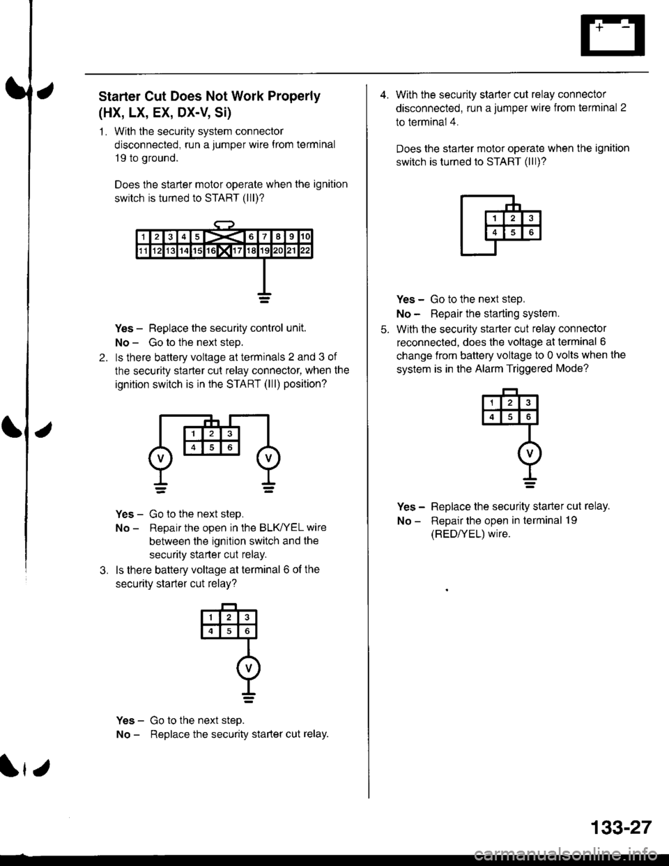
Starter Cut Does Not Work Properly
(HX, LX, EX, DX-V, Si)
1 . With the security system connector
disconnected, run a jumper wire f rom terminal
19 to ground.
Does the starter motor operate when the ignition
switch is turned to START (lll)?
2.
Yes - Replace the security control unit.
No - Go to the next steD.
ls there baltery voltage at terminals 2 and 3 of
the security starter cut relay connector, when the
ignition switch is in the START (lll) position?
Yes - Go to the next step,
No - Reoair the ooen in the BLK/YEL wire
between the ignition switch and the
security starter cut relay.
ls there battery voltage at terminal 6 of the
securitv starter cut relav?
Yes - Go to the next steo.
No - Replace the security starter cut relay.
3.
@
I=
r
133-27
4. With the security starter cut relay connector
disconnected, run a jumper wire from terminal 2
to terminal 4.
Does the slarter motor operate when the ignition
switch is turned to START (lll)?
5.
Yes - Go to the next step,
No - Repair the starting system.
With the security starter cut relay connector
reconnected, does the voltage at terminal 6
change from battery voltage to 0 volts when the
system is in the Alarm Triggered Mode?
Yes - Replace the security starter cut relay.
No - Repair the open in terminal 19
(BED/YEL) wire.
4
I=
Page 2070 of 2189
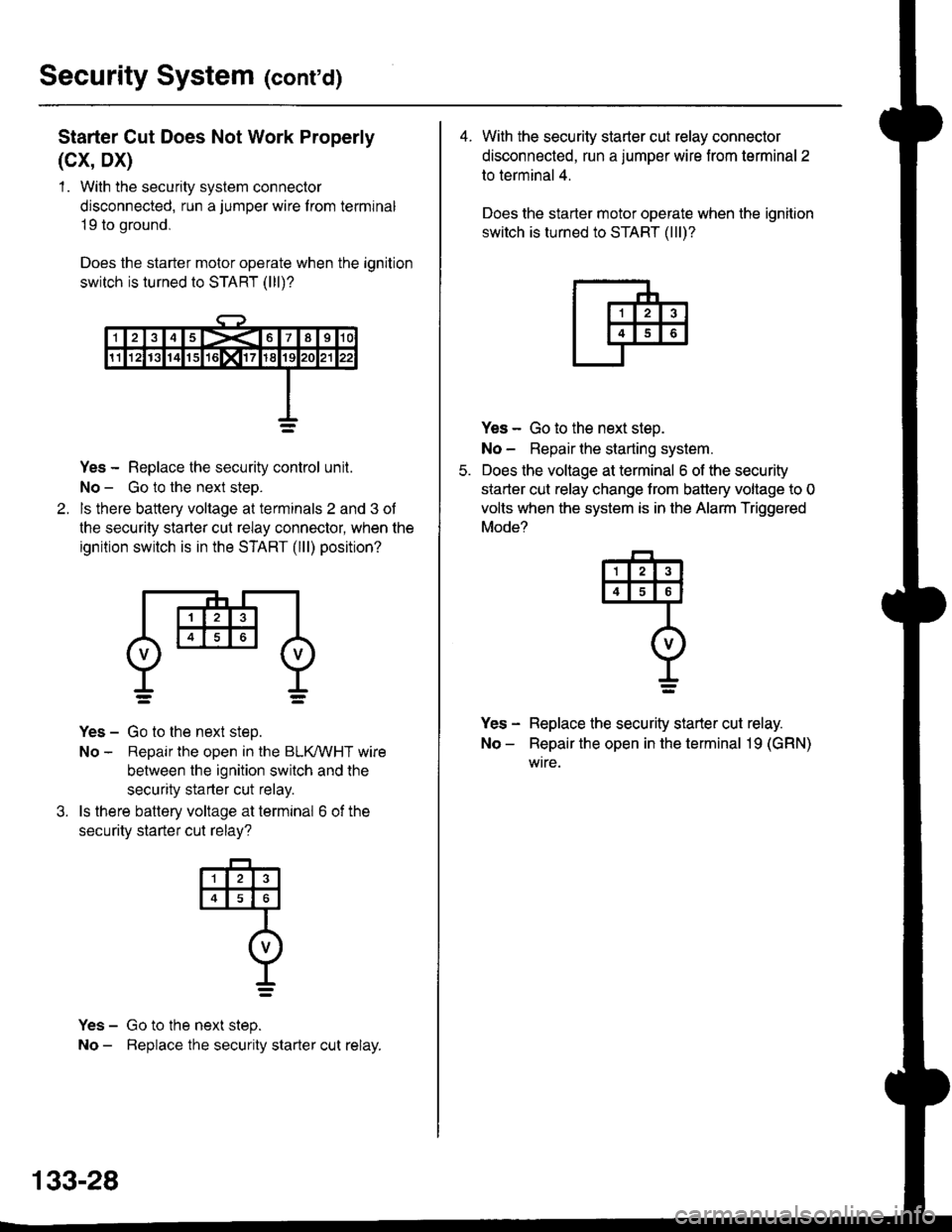
Security System (cont'd)
Starter Cut Does Not Work Properly
(cx, Dx)
1 . With the security system connector
disconnected, run a jumper wire f rom terminal
19 to ground,
Does the starter motor operate when the ignition
switch is turned to START (lll)?
Yes - Replace the security control unit.
No - Go to the next steo.
ls there battery voltage at terminals 2 and 3 of
the security starter cut relay connector, when the
ignition switch is in the START (lll) position?
Yes - Go to the next step.
No - Repair the open in the BLKMHT wire
between the ignition switch and the
security starter cut relay.
ls there battery voltage at terminal 6 of the
securitv starter cut relav?
Yes - Go to the next step.
No - Beplace the security starter cut relay.
4
o
t_=
133-28
4. With the security starter cut relay connector
disconnected, run a jumper wire from terminal 2
to terminal 4.
Does the starter motor operate when the ignition
switch is turned to START (lll)?
Yes - Go to the next steo.
No - Repair lhe starting system.
Does the voltage at terminal 6 of the security
starter cut relay change trom battery voltage to 0
volts when the system is in the Alarm Triggered
Mode?
Yes - Replace the security starter cut relay.
No - Repair the open in the terminal 19 (GRN)
wtre.
q
I=
Page 2075 of 2189
How the Circuit Works
The two outside mirrors are controlled by the power
mirror switch. Each mirror has two reversible
motors: one motor moves the mirror up and down
and the other motor moves the mirror lett and right.
The power mirror switch contains four switches to
control mirror adjustment, and two switches to
select the left or right mirror With the ignition in ON
(ll), battery voltage is supplied to the power mirror
swrtch. The mirror selector switch directs voltage
from two of the direction switches to either the left
or the right mirror.
Mirror Up
When you press the "up" edge of the mirror
adjustment button, ground is supplied from one of
the up/down switch contacts to both mirrors; battery
voltage is supplied from the opposite up/down
switch contact through the mirror select switch. lf
the mirror select switch is in the left or right position,
battery voltage is supplied to the corresponding
mirror uo/down motor which then tilts the selected
mtrror uD.
Mirror Down
When you press the "down" edge of the mirror
adjustment button, battery voltage is supplied Irom
one of the up/down swilch contacts to both mirrors;
a ground is supplied from the opposite up/down
switch contact through the mirror select switch. lf
the mirror select switch is in the left or right position,
battery voltage is supplied to the corresponding
mirror up/down motor which then tilts the selected
mrrror oown.
Mirror Left
When you press the "|eft" edge of the mirror
adjustment button, battery voltage is supplied from
one of the lefuright switch contacts to both mirrors;
a ground is supplied from the opposite lefuright
switch contact through the mirror select switch. lf
the mirror select switch is in the left or right position,
battery voltage is supplied to the corresponding
mirror lefvright motor which then tilts the selected
mirror to the lett.
Mirror Right
When you press the "right" edge of the mirror
adjustment button, ground is supplied from one of
the lefvright switch contacts to both mirrors; battery
voltage is supplied from the opposite left/right switch
contact through the mirror select switch. lf the mirror
select switch is in the left or right position, battery
voltage is supplied to the corresponding mirror
lefuright motor which then tilts the selected mirror to
the right.
Refer to the Service Manual (Section 23, Electrical)
for speclfic tests of troubleshooting procedures
141-1
Page 2077 of 2189
How the Circuit Works
The two outside mirrors are controlled by the power
mirror switch. Each mirror has two reversible
motors: one motor moves lhe mirror uo and down
and the other motor moves the mirror left and right.
The power mirror switch contains four switches to
control mirror adjustment, and a switch lo select
the left or right mirror. With the ignition ON (ll),
battery voltage is supplied to the power mirror
switch. The mirror selector switch directs voltage
Irom the direction switches to either the left or rioht
mtrror.
Mirror Up
When you press the "up" edge of the mirror
adjustment button, voltage is supplied from one of
the UP switch contacts to both mirrors. With the
mirror select switch in the LEFT or RIGHT Dosition.
ground is provjded for the corresponding up/down
motor through the opposite UP switch contact.
Battery voltage is supplied to the mirror up/down
motor which then tilts the selected mirror uo.
Mirror Down
When you press the "down" edge of the mirror
adjustment button, ground is provided through one
of the DOWN switch contacts to both mirrors.
With the mirror select switch in the LEFT or RIGHT
position, voltage is supplied to the corresponding
up/down motor through the opposite DOWN switch
contact. Battery voltage is supplied to the mirror
up/down motor which then tilts the selected
mtrror down.
Mirror Left
When the mirror select switch is in the LEFT or
RIGHT position, and you press the "lett" edge of the
mirror adjustment button, voltage is supplied to both
corresponding mirror motors through one of the
LEFT switch contacts. Ground is provided for the
corresponding lefvright motor through the opposite
LEFT switch contact, 8attery voltage is supplied to
the mirror left /right motor which then tilts the
selected mirror left.
I,J
141-3
Mirror Right
When the mirror select switch is in the LEFT or
RIGHT position, and you press the '?ight" edge of
the mirror adjustment button, ground is provided to
both corresponding mirror motors through one of
the RIGHT switch contacts. Voltage is supplied to
the corresponding leruright motor through the
opposite RIGHT switch contact. Battery voltage is
supplied to the mirror left /right motor which then
tilts the selected mirror right.
Mirror Detoggers
With the ignition switch in ON (ll), battery voltage is
supplied to the mirror defogger switch. When you
press the mirror defogger switch ON, voltage is
supplied to both mirror defoggers, causing them to
heat up and remove any fog from the mirrors. The
opposite side of each defogger grid is connected to
g rou no.
Refer to the Service Manual (Section 23,
Body Electrical) for specific tests and
troubleshooting procedures.
Page 2108 of 2189
-
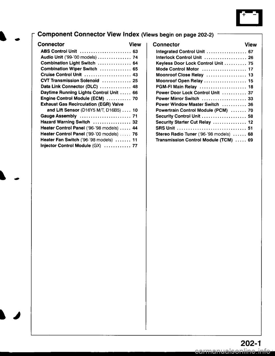
Component Connector View Index (Views begin on page 202-21
Connector View
ABS Control Unit........ ......63
Audio Unit ('99-'00 models) ......74
Combination Light Switch . . . . . . . . . . . . . . . 64
Combination Wiper Switch . . . . . . . . . . . . . . 65
Cruise Control Unit.... .....43
C\TTTransmission Solenoid ............. 25
Data Link Connector (DLC) ..... 48
Daytime Runnlng Lights Control Unit ..... 66
Engine control Module (ECM) ...........70
Exhaust Gas Recirculation (EGR) Valve
and Lift Sensor (D16Y5 Mfl, D1685) . . . . 10
Gauge Assembly .............71
HazardWarnlngSwitch,,. .,,,...,,,,... 32
Heater Control Panel ('96-'98 models) .....44
Heater Control Panel ('99-'00 models) ...., 76
Heater Fan Switch ('96-'98 models) ,,,.... 11
fniector Control Module (GX) ............77
I/
202-1
Connector View
Integrated Control Unit .......,. 67
f nterfock Control Unit .... ...... 26
Keyfess Door Lock Control Unit . . . . , . . . . . 75
Mode Control Motor ... ........'17
Moonroof Close Relay .. .......13
Moonroof Open Relay ... .......15
PGM-FI Main Relay .. .......... 18
Power Door Lock Conlrol Unil ..... ...... 37
Power Mirror Switch .,... ...... 33
Power Window Master Switch .,.........36
Powertrain Control Module (PCM) .......70
Security Control Unit ..., ..,,... 58
Security Starter Cut Belay ... ...,,,....,, 12
SRS Unit ............. 51
Stereo Radio Tuner ('96-'98 models) ...... 68
Transmission Control Module CICM) .....69
Page 2111 of 2189
Connector Views (cont'd)
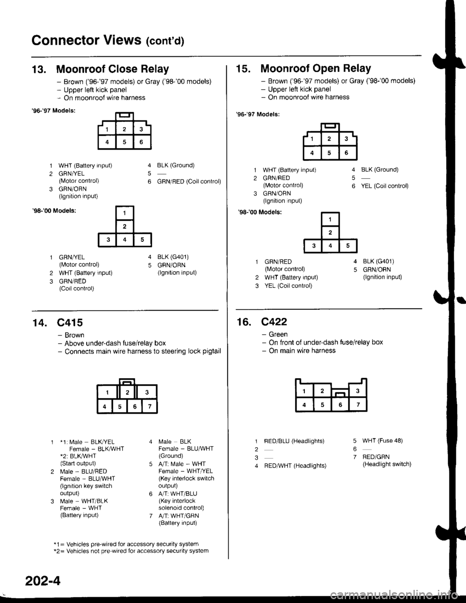
13. Moonroof Close Relay
'96-�97 Models:
1 WHT (Battery input)
2 GRN//EL
{Motor conirol)
3 GRN/ORN(lgnition lnput)
- Brown ('96-'97 models) or Gray ('98-'00 models)- Upper left kick panel- On moonroof wire harness
5
6
BLK (Ground)
GBN/RED (Coilconkol)
'98r00 Models:
GRN/YEL(Motor control)
WHT (Battery input)
GRN/RED(Coil control)
4 BLK (G401)
5 GRN/ORN(lgnition input)2
3
15. Moonroof Open Relay
- Brown ('96-'97 models) or Gray ('98-'00 models)- Upper left kick panel- On moonrool wire harness
'96.�97 Models:
1 WHT (Battery input)
2 GRN/FED(lvlotor control)
3 GRN/ORN(lgnition input)
'98r00 Modelsi
BLK (Ground)
YEL (Coil conkol)
5
6
GBN/RED(lvlotor control)
WHT (Battery input)
YEL (Coil control)
4 BLK (G401)
5 GRN/ORN(lgnition input)2
3
,1^t
6
14. C415
- Brown- Above underdash fuse/relay box- Connects main wire harness to steering lock pigtail
* 1: [,4ale BLKryELFemale - BLKMHT*2: BLK,/WHT(Start oulput)
l\.4ale - BLU/REDFemale - BLUruVHT(lgnilion key switchoutpur)
N4ale - WHT/BLKFemale - WHT(Battery input)
l\,4ale BLKFemale - BLU^VHT(Ground)
Ani Male - WHTFemale - WHT /EL
(Key interlock switchourpur)
A/T:WHT/BLU(Key interlocksolenold control)
A"rT: WHT/GRN(Battery inpul)
*1= Vehicles pre-wired for accessory security system*2= Vehicles not pre wired for accessory security system
202-4
16. C422
- Green- On tront ol under-dash tuse/relay box- On main wire harness
7
l
2
3
4
5
6
7
FED/BLU (Headlights)
REDAVHT (Headlights)
WHT (Fuse 48)
BED/GRN(Headlight switch)
Page 2112 of 2189
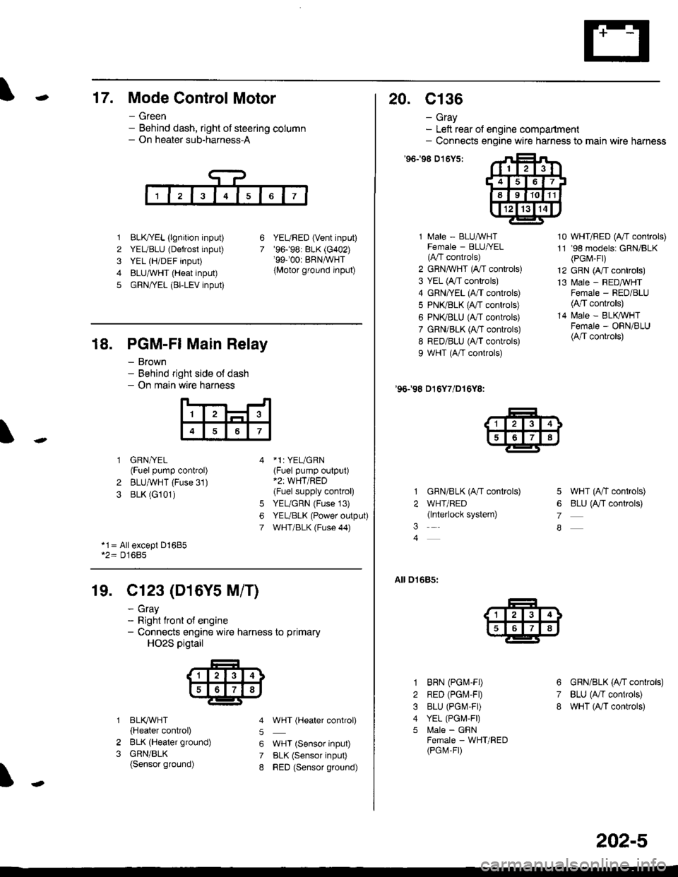
-17. Mode Control Motor
- Green- Behind dash, right of steering column- On heater sub-harness-A
1 BLK,TYEL (lgnition input)
2 YEUBLU (Detrost input)
3 YEL (H/DEF input)
4 BLUA/VHT (Heat input)
5 GRN/YEL (BI-LEV input)
YEURED (Vent input)'96.�98: BLK (G402)'99-'00r BRNAVHT
{Motor ground input)
6
7
18. PGM-FI Main Relay
- Brown- Behind right side o{ dash- On main wire harness
'l
4
1 GRN/YEL(Fuel pump control)
2 BLUAVHT (Fuse 31)
3 BLK (G101)
*1: YEUGRN(Fuel pump output)*2: WHT/RED(Fuel supply control)
YEUGRN (Fuse 13)
YEUBLK (Power output)
WHT/BLK (Fuse 44)
6
7
*1= All except Dl685*2= D16Bs
19. Cl23 (D16Y5 M/T)
2
3
BLI(WHT
{Heater control)
BLK (Heater ground)
GRN/BLK(Sensor ground)
- cray- Right tront o{ engine- Connects engine wire harness to primary
HO2S pigtail
5
6
7
8
WHT (Hgater control)
WHT (Sensor input)
BLK (Sensor input)
RED (Sensor ground)
20. c136
- Gray- Left rear of engine compartment- Connects engine wire harness to main wire harness
'96198 D't6Y5:
1 Male - BLUAVHTFemale - BLU|/EL(A"/T controls)
2 GRN,^WHT (A,/T controls)
3 YEL (A/T controls)
4 GRN/YEL (A/T controls)
5 PN(BLK (fff gs6lrq;s;
6 PNI(BLU (A/T controls)
7 GRN/BLK (Ar/T controls)
8 RED/BLU (A/T controls)
9 WHT (A/T controls)
'96198 D16Y7/D16Y8:
GRN/BLK (A/T controls)
WHT/RED(lnterlock system)
10 WHT/RED (A"/T controls)
11 '98 models: GRN/BLK(PGr,4-Fr)
12 GRN (A/T controls)
13 l\4ale - REDMHTFemale - RED/BLU(4,/T controls)
14 N4ale - BLIVWHTFemale - ORN/BLU(A/T controls)
5 WHT (A/T controls)
6 BLU (Antf se11re;s;
7
A
01685:
3
1
2
3
4
5
6
7
8
BRN (PGM-FD
RED (PGIV-FD
BLU (PGI\4-FD
YEL (PGI,4,F|)
l\4ale - GFNFemale - WHT/RED(PGM-FD
GRN/BLK (A'tl gs6trels;
BLU (A/T controls)
wHT (A/I controls)
202-5