Page 1831 of 2189

How To Use This Manual
Troubleshooting Tests
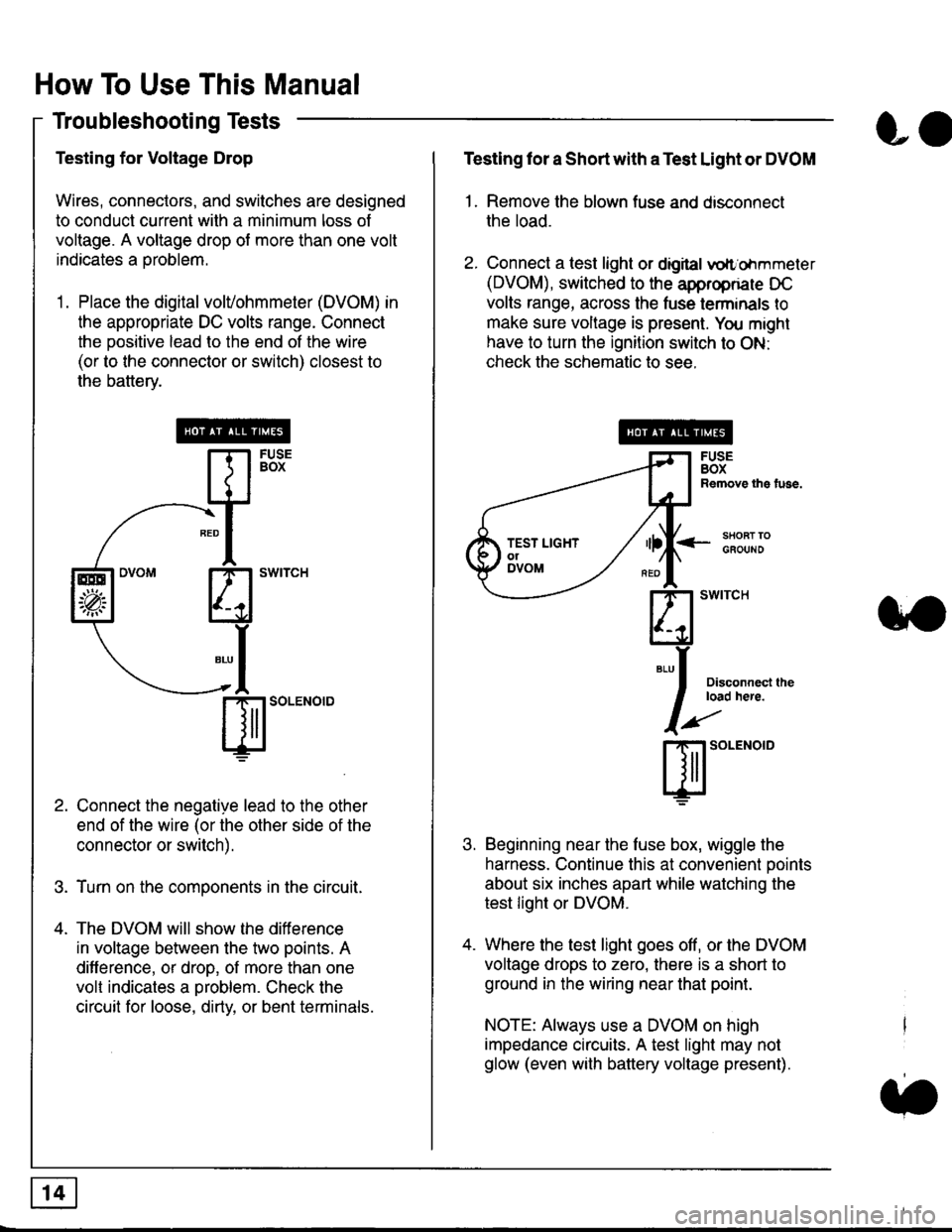
Testing for Voltage Drop
Wires, connectors, and switches are designed
to conduct current wilh a minimum loss of
voltage. A voltage drop of more than one volt
indicates a Droblem.
'1. Place the digital volVohmmeter (DVOM) in
the appropriate DC volts range. Connect
the positive lead to the end of the wire
(or to the connector or switch) closest to
the bafterv.
Connect the negative lead to the other
end of the wire (or the other side of the
connector or switch).
Turn on the components in the circuit.
The DVOM will show the difference
in voltage between the two points. A
difference, or drop, of more than one
volt indicates a oroblem. Check the
circuit for loose, dirty, or bent terminals.
co
Testing lor a Short with a Test Light or DVOM
1. Remove the blown fuse and disconnect
the load.
2. Connect a test light or digital
oltr'ohmmeter
(DVOM), switched to the appropnare DC
volts range, across the tuse lerminals to
make sure voltage is present. You might
have to turn the ignition switch to ON:
check the schematic to see.
<-s80RT TOGFOUNO
Disconnecl lheload here.
Beginning near the luse box, wiggle the
harness. Continue this at convenient ooints
about six inches apart while watching the
test light or DVOM.
Where the test light goes off, or the DVOM
voltage drops to zero, there is a short to
ground in the wiring near that point.
NOTE: Always use a DVOM on high
impedance circuits. A test light may not
glow (even with battery voltage present).
3'�'
ffito.'"o'o
.t.
TEST LIGHTolDVOM
Page 1832 of 2189

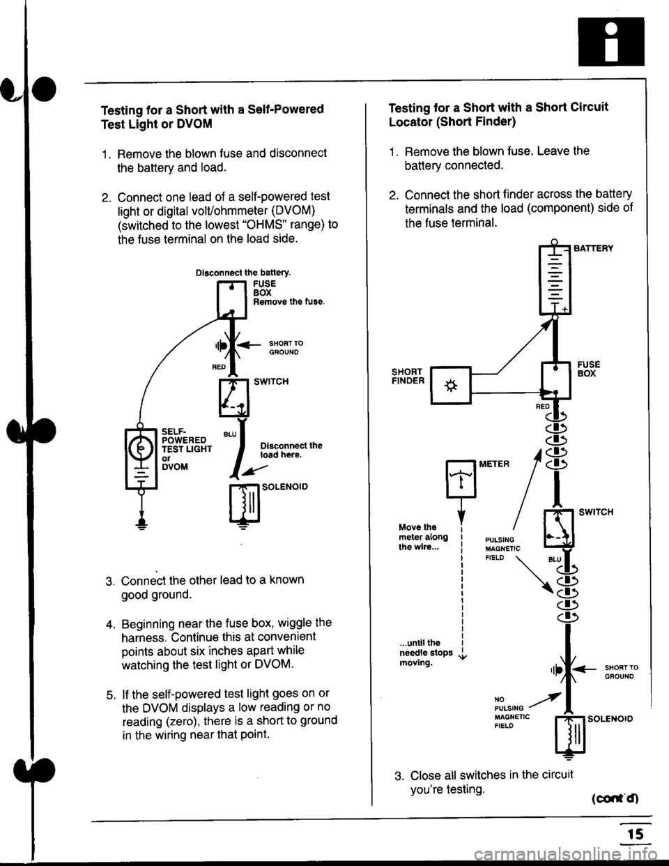
Testing for a Short with a Sell-Powered
Test Light or DVOM
1. Remove the blown fuse and disconnect
the battery and load.
2. Connect one lead of a self-powered test
light or digital volUohmmeter (DVOM)
(switched to the lowest "OHMS" range) to
the fuse terminal on the load side.
Dlsconnect the batlery.
FUSEBOXRemove the fuse.
<- ssoRr rociouNo
Dlsconnect theload here.
.)"'
r| SOLENOID
Connect the other lead to a known
good ground.
Beginning near the fuse box, wiggle the
harness. Continue this at convenient
points about six inches apart while
watching the test light or DVOM.
lf the self-powered test light goes on or
the DVOM displays a low reading or no
reading (zero), there is a short to ground
in the wiring near that Point.
SELF.POWEREDTEST LIGHTo1DVOM
4.
5.
Testing tor a Short with a Short Circuit
Locator (Short Finder)
1 . Remove the blown fuse. Leave the
battery connected.
2. Connect the short finder across the battery
terminals and the load (component) side of
the fuse terminal.
SATTERY
SHORTFINOER
FUSEBOX
PULSINGMAGNETICFIELD \
NOPUISING
\
I swtrcH
I
<- stl
Kl"I- -.T.1
"'at
\8
d)
.r.
rlll<
,l
m
...unilltheneedle slopsmoving.SHOFTTGFOUNO'llt
No --tPULS|NG z
MAGNETTC IFIELD ISoLENOTO
3. Close all switches in the circuil
you're testing. (co,f,O
r5
Page 1833 of 2189
How To Use This Manual
Troubleshooting Tests (cont'd)
4. Turn on the short finder. This creates a
pulsing magnetic field around the wiring
between the fuse box and the short.
5. Beginning at the fuse box, slowly move
the short finder along the circuit wiring.
The meter will show current Dulses
through sheet metal and body trim. As
long as the meter is between the fuse and
lhe short, the needle will move with each
current pulse. Once you move the meter
past the point of the short, the needle will
stop moving. Check the wiring and
connectors in this area to locate the cause
of the short.
co
Page 1834 of 2189
![HONDA CIVIC 2000 6.G Workshop Manual Fuse/Relay Information
- Under-dash Fuse/Relay Box
Front View
c712(To moonroof wire harness)
. : Canadai : Not UsedO : C926 loprion (+B)l
@ : C927 loption (dash lights)]
O : C928 [Option (ACC]I
@ : C9 HONDA CIVIC 2000 6.G Workshop Manual Fuse/Relay Information
- Under-dash Fuse/Relay Box
Front View
c712(To moonroof wire harness)
. : Canadai : Not UsedO : C926 loprion (+B)l
@ : C927 loption (dash lights)]
O : C928 [Option (ACC]I
@ : C9](/manual-img/13/6068/w960_6068-1833.png)
Fuse/Relay Information
- Under-dash Fuse/Relay Box
Front View
c712(To moonroof wire harness)
. : Canadai : Not UsedO : C926 loprion (+B)l
@ : C927 loption (dash lights)]
O : C928 [Option (ACC]I
@ : C929 loption (lc2)l
Rear View
css2
c421(To main wire harness)
c801CI-o SRS main harness)
c501(To dashboard wire harness)
^ : Not used ('96-'97 models)
c913(To ignition switch)
INTEGRATEDCONTROL UNITCONNECTOR A
c419Oo main wire harness)
REAR WINDOWDEFOGGER RELAY
TURN SIGNAUHAZARD RELAY
c423(To main wire harness)
co
c422(To main wire harness)
POWERwtNDowRELAY
c551flo lloor wire harness)c439 f96.'97 MODELSand ALL GX MOOELS)(To main wire harness)
T1 T-t T"l T"t r-r r-'l T1 F n r-l r-l r'123 24 25 26 27 28 29 30 31 32 33I-J I.J I.J IJ IJ IJ LJ IJ IJ I.J I.J I-I
r"1 r-t r-t T-l r"l r-r Fl r:1 n rJ n -12 13 14 t5 16 17 t8 19 2A 2t 22LI I.J L! LI tJ LJ (J LI IJ IJ T-I I.J
n r:l rj.l |-l T"l Tl r:t n r-l |;.l r-r r-l1 2 3 4 5 6 7 I 9 10 11LI LI IJ LJ LJ I,J T-I I.J TJ IJ I.-I tJ
c420(To main wire harness)
6
(To floor wire harness)
Page 1836 of 2189
- Under-dash Fuse/Relay Box (cont'd)
Fuse/Relay I nformation
Fuse
NumberFuse NameAmps
(P/W RELAY)
(S/R RELAY)
FR WIPER
FR WASHER
LO
Page
10-7 |
I
Component or Clrcuit Protected
i Power window relay, Moonrool
Front wioer/washer
CIGARETTE
LIGHTER
ACC SOCKET
10-7Accessory power socket
I RAD|O CLOCK
I
110 115)l
tl
1O-7 |
I
Stereo radio tuner ('96198 models), Audio unit ('99100
model)
Not used
i 7.5i 114 iDash & console lights
I srnnrensrorunl | 7.slzl , zt -t , ! eCU-n main retay, PCM/ECM, Integrated controt unit
I ot 21-2 t
I LICENSE LIGHTS I 7.5
I rerr uesls I
Parking lights, License plate lights, Tail lights| 1oo-1 |
tl
| (f NTERLOCK UNIT) | 7.5 | 10-12 I Interlock system
* = '98 models
6-2
Page 1837 of 2189
- Under-hood ABS Fuse/Relay Box
Fuse
Number
(To underhood ABS fuse/relay box w re harness)
ABS pump motor
| 10-14 I ABS control unit
i ABS control unit
component or circuit ProiectedFuse Name
PUMP MOTOR
I ABS +B
ABS PUMPMOTOR RELAY(To main wire harness)
(To rnain wlre harness)
I!,ITR CHECK
6.3
Page 1838 of 2189
Fuse/Relay Information lcont'd)
- Under-hood Fuse/Relay Box
Front View
T'102(To engine wire harness)
LO
T1Oo starter cables)
*: Not Used
Rear View
c353To main wire harness
DE
tr
tr
tr
t-l
IJ
n
tJ
t-l51
IJ
n
IJ
n5T
IJ
[[o main wire harness)
6-4
ffo main wire harness)fto main wire harness)
Page 1842 of 2189

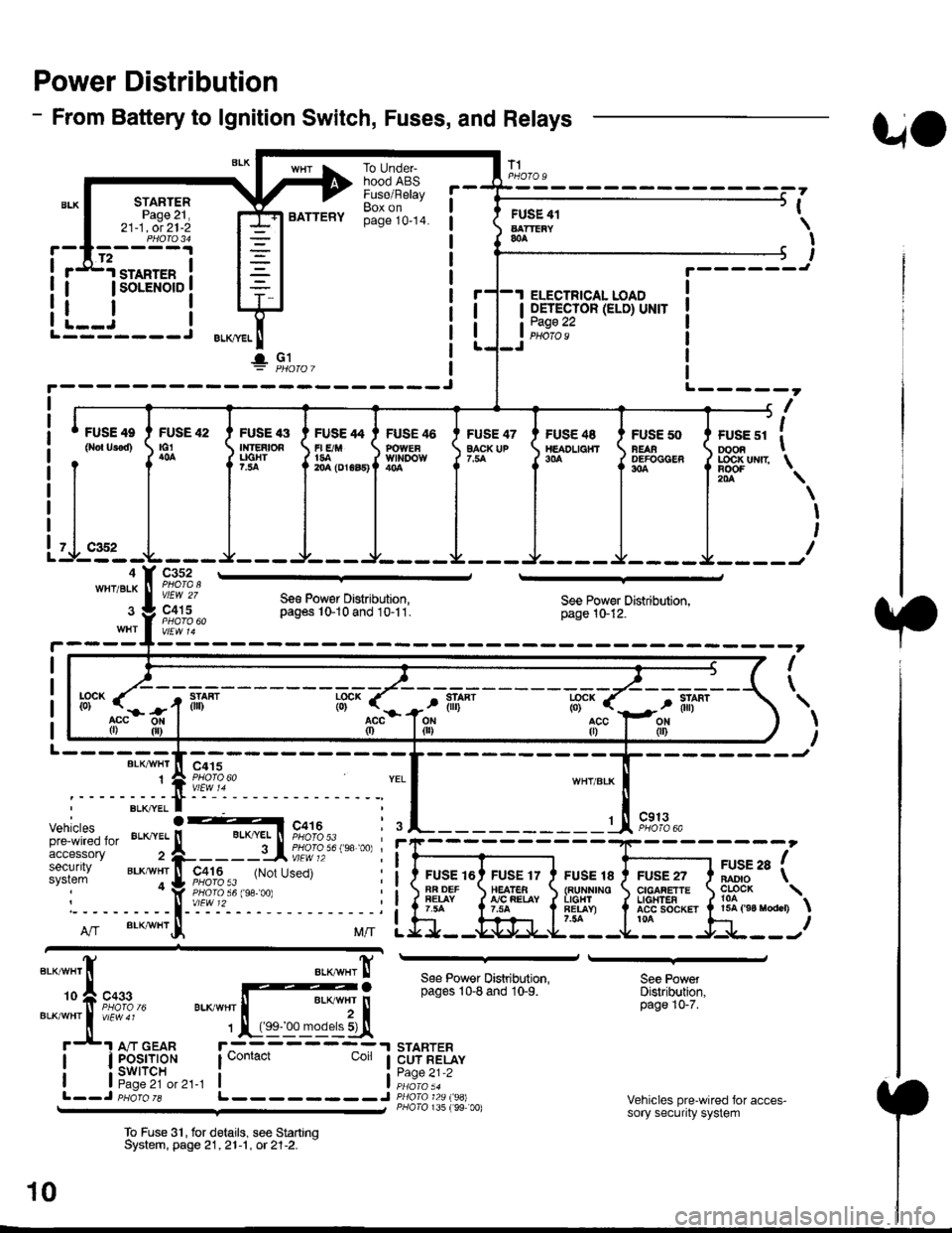
Power Distribution
- From Battery to lgnition Switch, Fuses, and Relays
STARTERPage 21,21-1, ot 21-2
.d1.ro"rr" i
I lsoLENorD I
FUSE 42tG1
BATTERY
To UndeFhood ABSFuse/RelayBox onpage 10-14.
FUSE 47EACK UP
T1
FUSE 41AATTEiY&A
I OETECTOR (ELD) UNIT
tii::.':
UO
PHOfO U
,
I
I
I
t.------J
ELECTRICAL LOAD
i--i rL---- J ELKml
!" Gl
FUSE 4e
0ro{ Urod)FUSE '13Ir|]EAtOAUGHT?.:ta
FUSE 46POWEaWll'IDOW
FUSE /t4
r| E/M1{rA204 (DrGa5)
FUS€ 48TtEADL|a}fT9|'A
FUSE 50NEAAOEFOCGER304
+------, f| ',
I ruse sr I oooa I
J LOC|( uNrr \
il-.4WHT/BLK
Itr '\
\
I
I
I
c352
vlEW 27
c415Se€ Pow€r Distribution,pag6s 10-10 and 10-11.See Power Distribution,page 10-12.
I
\
L------BLK/VI/HT
1
--------Jc415
Vehiclespre-wired foraccessorysecuritysystem
c913PHOTO 6A
FUSE 16AR DEFFEIAY
FUSE 17HEATEA!'/C FEIAY
FUSE 18{RUNNINOL|GHlFET.AY)7.54
FUSE 27CIGAFETTEL|oHTEAACC SOCKET ta
arse ra fBADIO \
?o?"* \15A ('94 raodcr)
ff".acc0)
llL--------J
See Power Distribution,pages 10-8 and 10-9.
STARTERCUT RELAYPage 21-2
P/lolo 135 (99 00)
See PowetDistribution,page 10-7.
Vehicles pre-wired for acces-sory security system
To Fuse 3'|, for delails, see StartrnqSystem, page 21,21-1 , ot 21-2. -
10