Page 1383 of 2189
ls there approx. 2 - 3 ohms?
Check for an open in the wire(s):1. Reconnect the blower resistor
4P connector,2. Remove the center dashboardlower cover (see section 20),and disconnect the heater fanswitch 6P connector.3. Turn the ignition switch ON (ll).
4. Ground each of these termi-nals individually in the tollow_ing order: No. 4, 2, 5 and 3.
Does the blower motor run atprogressively higher speeds?Reolace the hoater fan switch.
Repair open or cause ol excessiveresistance in the appropriatewire{sl between the blower resis-tor and the heater {an switch.
Check the blower resislor:1. Turn the ignitjon switch OFF.2. Disconnect the blower resistor 4P connector.3, N4easure the resistancebetween the No. 2 and No. 4
terminals of the blower resis-tor,
BLOWER RESISTOR
HEATER FAN SWITCH 6P CONNECTOR
BLU/WHT
2
16
BLUBLU/YEL
BLU/BLK
JUMPERWIRE
Wire side of female terminals
21-9
Page 1385 of 2189
From page 2l 10
Check for an open in the wire:
1. Turn the ignition switch OFF,and disconnect the iLrmPer
2. Remove the center dashboardlower cover (see section 20),
and disconnect the heater fanswitch 6P connector.3. Turn the ignition switch ON (ll).
4. Measure the voltage between
the No. 3 terminal and bodygrou nd.
Repair op.n in th6 wiro betw€enthe blower motor and tho heaterfan switch.
Check for an open in the wire:
1. Turn the ignition switch OFF.2. Check for continuity between
the No. 1 terminal of the heatertan switch 6P connector and
body ground.
Reolaco tho heater fan iwitch
Check tor an op€n in the wire
betw.en the heater tan switchand body ground. ll th€ wilo b OK,
check tor poor ground at G401 and
G102.
HEATER FAN SWITCH 5P CONNECTOR
Wire side oI female terminals
(cont'd)
21-11
Page 1388 of 2189
Troubleshooting -'96 - 98 Models
Mode Control Motor lcont'dl
From page 2l-13HEATER CONTROL PANEL lilP CONNECTOR
Wire side of lemaie terminals
Check tor a short in the wi.e(s):1. Remove the center dashboardlower cover (see section 20),and disconnect the heater con-trol panel 14P connector.2. Check for continuity betweenthe No. 1, 4, 7, 8 and 9 termi-nals and body ground individ-
Raprir.ny short in the wire(s)betw€en the mode control motorand the heater control panel.
Check for a shon to power:
Check the same wires {or voltage.
Repair short to pow6r in thewiro(3) betwoen the mode con-lrol motor .nd tha heate. controlprnel, This short also damag.stho heater cont.ol prnel. Repailthe short to power b€{ore replac-ing the heeter conlrol pan6l.
ls there any voltage?
To page 21 15
21-14
Page 1391 of 2189

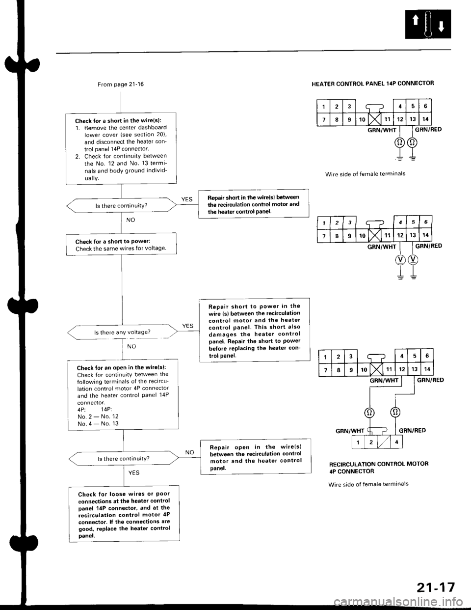
From page 21-16
ls there any voltage?
Check {or a short in the wire(s):1. Remove the center dashboardlower cover (see section 20),
and disconnect the heater con_
trol panel 14P connector'
2. Check for continuity between
the No. 12 and No. 13 termi-
nals and body ground individ-
Repair 5hort in the wire{sl between
the recirculation control motor and
the heater control Panel
Check Ior a short to Power:Check the same wires for voltage
Repair short to Power in the
wire {s) between the recirculationcontrol motor and the heater
control panel. This short also
damages the heater controlpanel. Repair the short to Powerbetore replacing the heater con-
trol panel.
Check lor an open in the wire(s):
Check for continuity between the
following terminals of the recircu
lation control motor 4P connector
and the heater control Panel 14P
4P. 14P:No.2 - No. 12No.4 No. 13
Repair open in the wirelsl
between the recirculation control
motor and the heater controlpanel.
ls there continuitY?
Check for loose wires or Poorconnections at the heater control
Danel 14P connector, and at the
recirculation control motor 4P
connector. lf the connections aregood, replace the heater control
Danel,
HEATER CONTROL PANEL 14P CONNECTOR
I;-?45
789'o lx11121314
GRN/WHT
0) (0
GRN/BED
Wire side of female terminals
GRN/RED
GRN/RED
RECIRCULATION CONTROL MOTOR
4P CONNECTOR
Wire side of female tetminals
I23i--?156
78I'olx11121314
GRN/WHT
V)(v
145
7IIrol\l rr1213
GRN/WHT
r zl/lt
21-17
Page 1392 of 2189

Troubleshooting -'96 - 98 Models
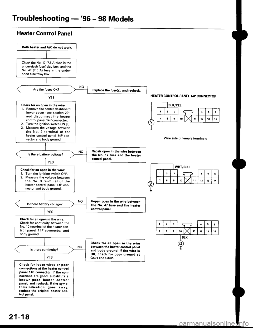
Both heater and A/C do not work.
Check the No. 17 {7.5 A) fuse in theunderdash fuse/relay box, and theNo. 47 (7.5 A) fuse in the underhood fuse/relay box.
R.phce the fuso{s), .nd rccheck.
Chack tor an open in the wi.e:1. Remove the center dashboardlower cover (see section 20),and disconnect the heatercontrol panel 14P connector.2. Torn the ignition switch ON {ll).3. Measure the voltage betweenthe No. 2 terminal of theheater control panel 14P con-nector and body ground.
Rcpair opGn in th€ wiro betwoonthe No. 17 tuse and the hoatclcontrol panel.
ls there baftery voltage?
Check for an opon in the wiro:1. Turn the ignition switch OFF.2. Measure the voitage betweenthe No. 3 terminal of theheater control panel 14P con-nector and body ground.
Rgprii open in th6 wira b€twacnthe No. il7 tui. and the heat.tcont.ol p.nal.
ls there battery voltage?
Check foi an open in the wi.e:Check for continuity between theNo. 10 terminal ot the heater con-trol panel 14P connector andbody ground.
Check lor an opon in tho wireb€{w6on the hoator control oaneland body ground. lI the wirc isOK, check tor poor ground atG401 .nd G4O2.
Check for looae wiaos or ooolconnections at the hoater controlpanol 14P connector. lf the con-nactions dre good. 3ubstitute tknown-9ood heater controlpanel, and rech6ck. It tho symp-tom/indication 9oe3 .wry,replace the original heatel con-trol oanol.
Heater Control Panel
HEATER CONTROL PANEL 1,lP CONNECTOR
Wire side of female terminals
21-18
Page 1413 of 2189

Heater Unit
Replacement
SRS components are located in this area. Review the
SRS component locations, precautions, and procedures
in the SRS section {24} before performing repairs or ser-
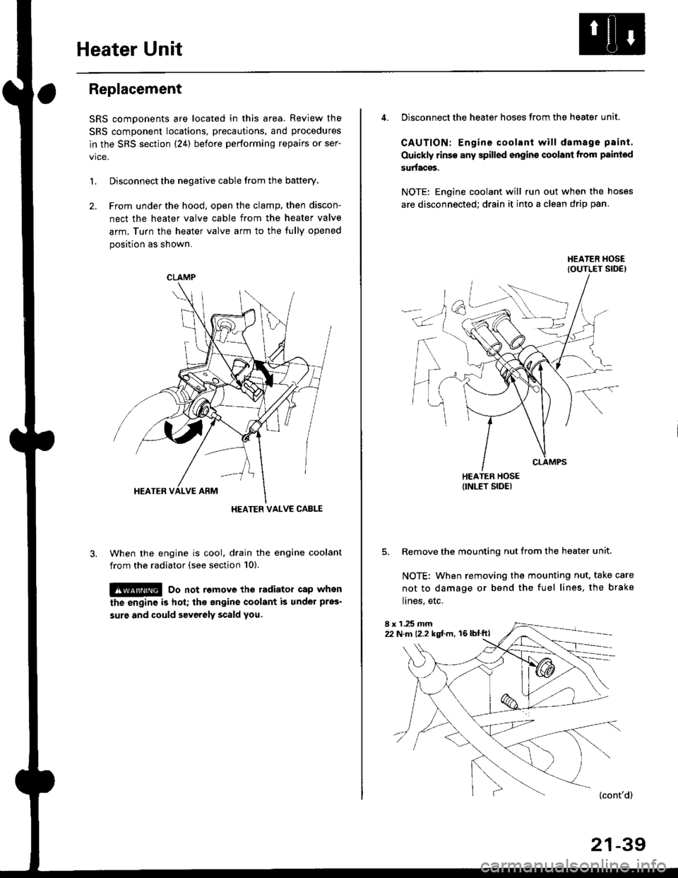
L Disconnect the negative cable from the battery.
2. Frcm under the hood, open the clamp, then discon-
nect the heater valve cable from the heater valve
arm. Turn the heater valve arm to the fully opened
position as shown.
When the engine is cool. drain the engine coolant
from the radiator (see section 10).
!@ Do not remove the radiator cap when
the engine is hot; the ongine coolant is under pres'
surg and could severely scald you.
CLAMP
HEATER VALVC CABLE
4. Disconnect the heater hoses from the heater unit.
CAUTION: Engine coolant will damage p8int.
Ouickly rinse any spilled engins coolant from painted
su aces,
NOTE: Engine coolant will run out when the hoses
are disconnected; drain it into a clean drip pan.
5. Remove the mounting nut from the heater unit.
NOTE: When removing the mounting nut, take care
not to damage or bend the fuel lines, the brake
lines, etc.
I x 1 .25 mm22 N.m {2.2 kgl.m, 16lblftl
21-39
Page 1414 of 2189
Heater Unit
Replacement (cont'dl
6.
7.
8.
9.
Remove the dashboard (see section 20).
Remove the heater duct (see page 21-37) or evapo-
rator (see page 22-28).
Disconnect the connectors from the mode control
motor and air mix control motor ('99 - 00 models),
then remove the wire harness clips and wire har-
ness from the heater unit. Remove the clip from the
heater duct, then remove the two mounting nuts
and the heater unit.
6x1.0mm9.8 N.m 11.0 kgl.m,7.2 lbf.ftl
HEATER UNIT
lnstall in the reverse order of removal. Make note of
the following items.
Apply sealant to the grommets.
Do not interchange the inlet and outlet heater
hoses. Make sure that the clamps are secure.
Refill the cooling system with engine coolant
(see section 10).
Connect all cables, and make sure they are prop-
erly adjusted (see page 21-44 (96 - 98 models)
or page 21-45 ('99 - 00 models)).
Make sure that there is no air leakage.
21-40
Page 1416 of 2189

Heater Control Panel
'95 - 98 modolsi
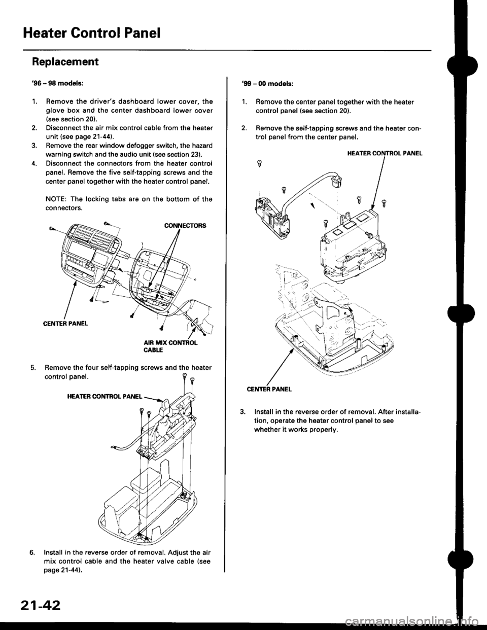
Remove the driver's dashboard lower cover, the
glove box and the center dashboard lower cover(see section 20).
Disconnect the air mix control cabls from the heater
unit {see page 21-44).
Remove the rear window defogger switch, the hazard
warning switch and the audio unit (see section 23).
Disconnect the connectors from the heater control
panel. Remove the five self-tapping screws and the
center panel together with the heater control panel.
NOTE: The locking tabs are on the bottom of the
connecrors.
Install in the .everse order of removal. Adjust the air
mix control cable and the heater valve cable {seepage 21-44)..
Replacement
1.
Remove the four self-tapping screws and the heater
21-42
1.
'9!, - 00 modols:
Remove the center panel together with the heater
control panel (see section 20).
Remove the self-tapping screws and the heater con-
trol panelfrom the center Danel.
Install in the reverse order of removal. After
tion, operate the heater control panel to see
whether it works properly.
installa-