Page 1508 of 2189
Gonnector ldentification and Wire Harness Routing
Msin Wire Harness (Right side oI dash branch)
Connector or
Terminal
Number of
CavitiesLocationConnects toNotes
c440
c441
c442
c443
c4M
c445
c446
c452
16
2
20
7
22
22
Under middle of dash
Under right side of dash
Under right side of dash
Under right side of dash
Behind right side of kick panel
Behind right side of kick panel
Under right side of dash
Under right side of dash
Heater sub-harness A (C721)
Service check connector
Junction connector
PGM-Fl main relay
ABS control unit
ABS control unit
Engine wire harness (C131)
ECM/PCM
G402Right kick panelBody ground, via main wire harness
*'l: '99 - 00 models
23-38
Page 1567 of 2189
JArmature Inspection and Test
1.Inspect the armature for wear or damage due to con-
tact with the permanent magnet or field winding.
. lf there is wear or damage. replace the armature.
Inspect for damage.
2. Check commutator surface and diameter.
. lf the surface is dirty or burnt. resurface with emery
cloth or a lathe within the following specifications,
or recondition with #500 or #600 sandpaper.
. lf commutator diameter is below the service limit,
replace the armature.
Commutator Diameter
Standard {NEW)Service Limit
28.0 - 28.1 mm
(1.102 - 1.106 in)
27.5 mm
(1.083 in)
VERNIER CALIPEB
3. Measure the commutator runout.
. lf the commutator runout is within the service
limit, check the commutator for carbon dust or
brass chips betlveen the segments.
. lf the commutator runout is not within the ser-
vice limit, replace the armature.
Commutator Runout
Standard (NEW)Service Limit
0 - 0.02 mm(0 - 0.0008 in)
u-u!r mm
(0.002 in)
COMMUTATOR
(cont'd)
23-97
Page 1568 of 2189
Starting System
Armature Inspection and Test (cont'dl
4. Check tor mica depth. lf necessary, undercut mica
with a hacksaw blade to achieve proper depth. l{ ser-
vice limit cannot be maintained, replace the armature.
MICA D€PTH
Commutator Mica D€pth
5. Check for continuity between the segments of the
commutator. lf an open circuit exists between any
segments, replace the armature.
NOT GOOD
Standard (NEW)Service Limit
0.4 - 0.5 mm
(0.016 - 0.02 in)
0.15 mm
(0.006 in)
23-98
corL coFECOMMUTATOR
6. Place the armature on an armature tester. Hold a
hacksaw blade on the armature core.
ARMATURE TESTER
. lf the blade is attracted to the core or vibrates
while the core is turned, the armature is shorted.
Replace the armature.
7. Check with an ohmmeter that no continuity exists
between the commutator and armature coil core,
and between the commutator and armature shaft. lf
there is continuity, replace the armature.
ARMATURE
Page 1569 of 2189

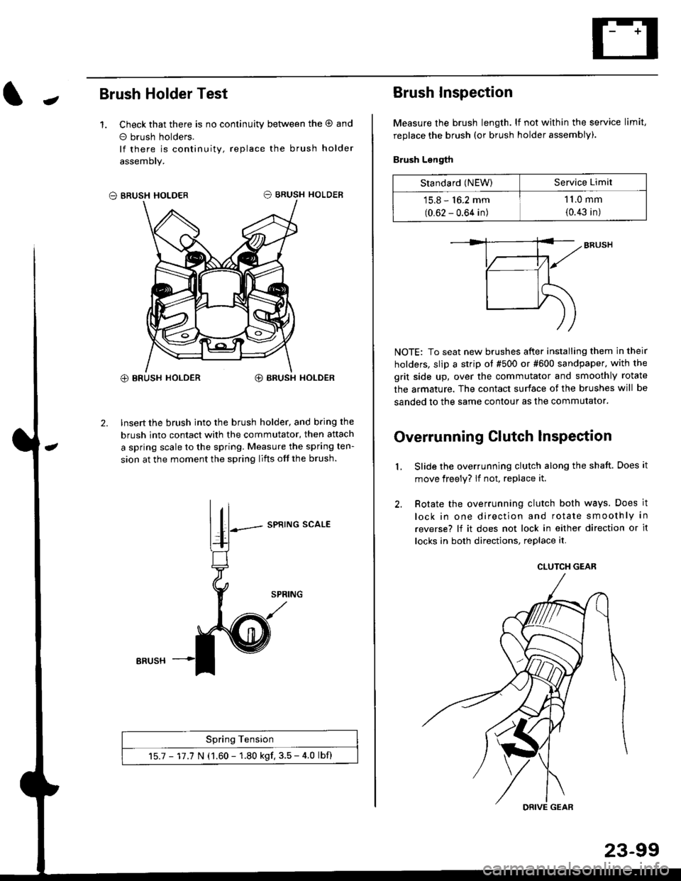
JBrush Holder Test
1. Check that there is no continuity between the O and
o brush holders.
lf there is continuity, replace the brush holder
assemoly.
O BRUSH HOLDER
@ BRUSH HOLDER€) BRUSH HOLDER
2. Insert the brush into the brush holder, and b.ing the
brush into contact with the commutator, then attach
a spring scale to the spring. Measure the spring ten-
sion at the moment the spring lifts off the brush.
SPRING SCALE
Spring Tension
15.7 - 17.7 N (1.60 - 1.80 kgf. 3.5 - 4.0 lbf)
ERUSH
Brush Inspection
Measure the brush length. lf not within the service limit,
replace the brush (or brush holder assembly).
Brush Length
NOTE: To seat new brushes after installing them in their
holders, slip a strip ot #500 or #600 sandpaper. with the
grit side up, over the commutator and smoothly rotate
the armature. The contact surface of the brushes will be
sanded to the same contour as the commutator.
Overrunning Clutch lnspection
Slide the overrunning clutch along the shaft. Does it
move freely? lf not, replace it.
Rotate the overrunning clutch both ways. Does it
lock in one direction and rotate smoothly in
reverse? lf it does not lock in either direction or it
locks in both directions, replace it.
2.
L
Standard (NEW)Service Limit
15.8 - 16.2 mm
(0.62 - 0.64 in)
1 1.0 mm
{0.43 in)
CLUTCH GEAR
DRIVE GEAR
Page 1572 of 2189
lgnition System
Component Location Index
IGNITION TIMING CONTROL SYSTEM
. Troubleshooting, section 11
. ldle speed Inspection/Adjustment. section 11
. Inspection and Setting, page 23-105
SERVICE CHECK CONNECTOR {2P}Iwiie colors: 8RN and BLKI
TEST TACI{OMETER CONNECTOB
IGNITION WIRESlnspection and Test, page 23-110
PLUGSInspection, page 23 1 11
Replacement, page 23'106Overhaul, page 23-107lgnition Coil Test, page 23'110lgnition Control Module llCM)Input Test, page 23-109
23-102
Page 1575 of 2189

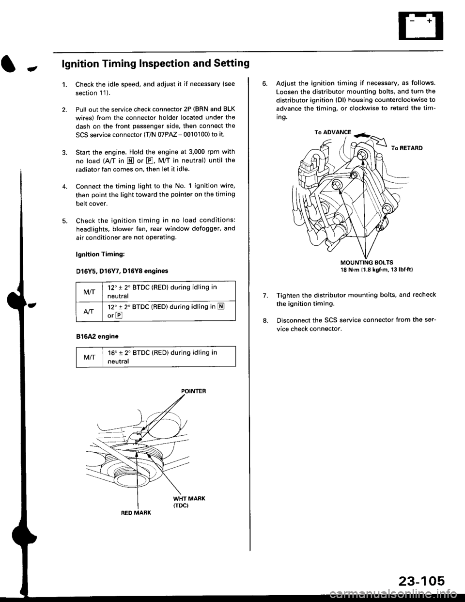
-lgnition Timing Inspection and Setting
1.Check the idle speed, and adjust it it necessary (see
section 'l '1 ).
Pull out the service check connector 2P (BRN and BLK
wires) from the connector holder located under the
dash on the front passenger side, then connect the
SCS service connector (T/N 07PAZ - 0010'100) to it.
Start the engine. Hold the engine at 3.000 rpm with
no load {A,/T in E or E. M/T in neutral) until the
radiator fan comes on, then let it idle.
Connect the timing light to the No. 1 ignition wire,
then point the light toward the pointer on the timing
belt cover.
Check the ignition timing in no load conditions:
headlights. blower fan, rear window defogger, and
air conditioner are not operating.
lgnhion Timing:
D15Y5. D16Y7, Dl6Yg engines
816A2 engine
MIT16" 12' BTDC (RED) during idling in
neutral
M/T12't 2" BTDC (RED) during idling in
neutral
l2'r 2" BTDC {RED) during idling in S
orE
POINTEB
RED MARK
23-105
ro ADVANCE -<;,
6. Adjust the ignition timing if necessary, as follows.
Loosen the distributor mounting bolts. and turn the
distributor ignition (Dl) housing counterclockwise to
advance the timing, or clockwise to retard the tim-
ing.
MOUNTING BOLTS18 N'm (1.8 kgfm, 13lblftl
Tighten the distributor mounting bolts, and recheck
the ignition timing.
Disconnect the SCS service connector from the ser-
vice check connector.
7.
Page 1593 of 2189

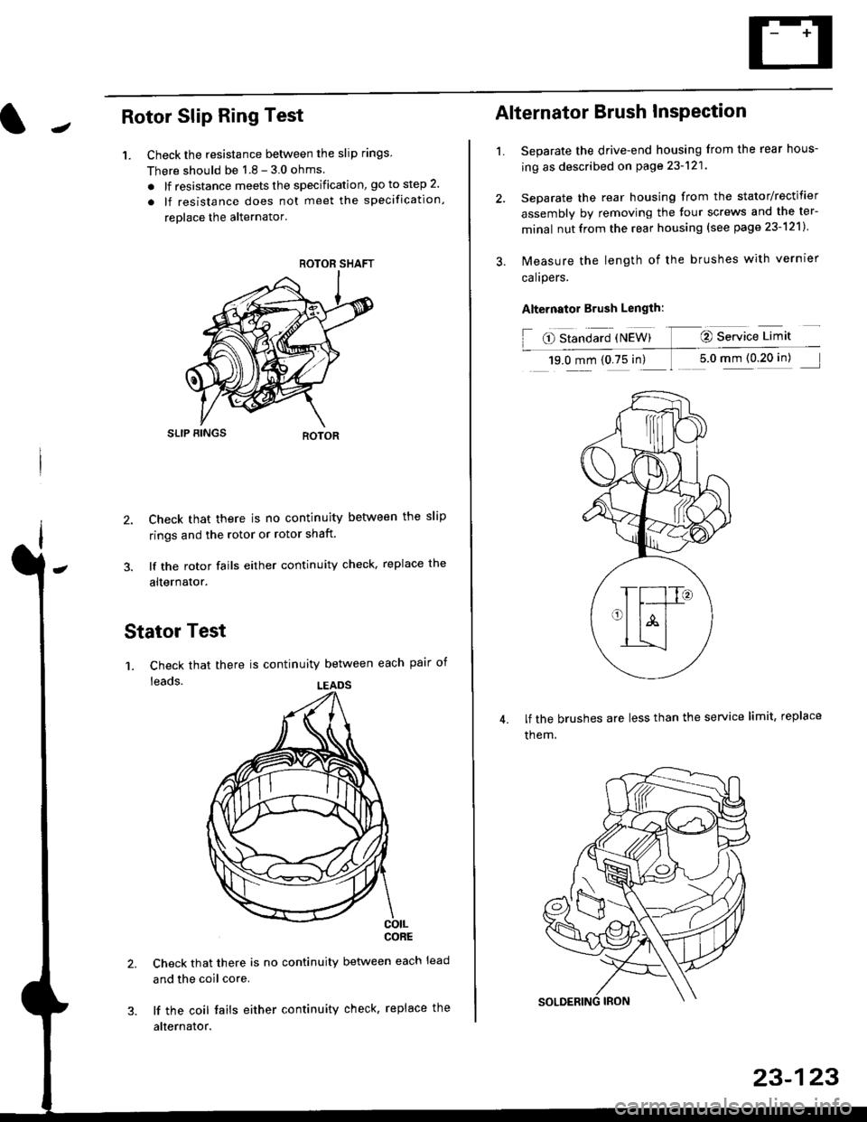
JRotor Slip Ring Test
1. Check the resistance betlveen the slip rings
There should be 1 8 - 3 0 ohms
. lf resistance meets the specification, go to step 2.
. lf resistance does not meet the specification,
reolace the alternator'
SLIP BINGS
2. Check that there is no continuity between the slip
rings and the rotor or rotor shaft.
3. lf the rotor fails either continuity check, replace the
alternator.
Stator Test
'1. Check that there is continuity between each pair of
leads.
CORE
Check that there is no continuity between each lead
and the coil core.
lf the coil fails either continuity check, replace the
alternator.
ROTOR SHAFT
LEADS
1.
Alternator Brush InsPection
Separate the drive-end housing from the rear hous-
ing as described on page 23-121
Separate the rear housing from the stator/rectifier
assembly by removing the four screws and the ter-
minal nutfrom the rear housing {see page 23-121}
lvleasure the length of the brushes with vernrer
calrpers.
Alternator Brush Length:
O Standard {NEW} @ Service Limit
19.0 mm (0.75 in) 1 5.0 mm (0 20 in)
lf the brushes are less than the service limit, replace
them.
23-123
Page 1598 of 2189
Gauge Assembly
Component Location Index
SRS components are located in this area. Review the SRS component locations, precautions, and procedures in the SRS
section (24) before performing repairs or service.
6x1.0mm9.8 N.m 11.0 kgf.m,22lbt.lrl
VEHICLE SPEED SENSOR {VSS)Troubleshooting, page 23-1 40
GAUGE ASSEMBLYGau ge/lndicator/TerminalLocation Index, page 23-129Removal, page 23-135Bulb Location, page 23-136Disassembly, page 23 138
PARKING BRAKE SWITCH
FLUIO LEVEL SW]TCH
23-128
ENGINE OIL PR€SSURE SWITCH