Page 1166 of 2189

Front Brake Disc
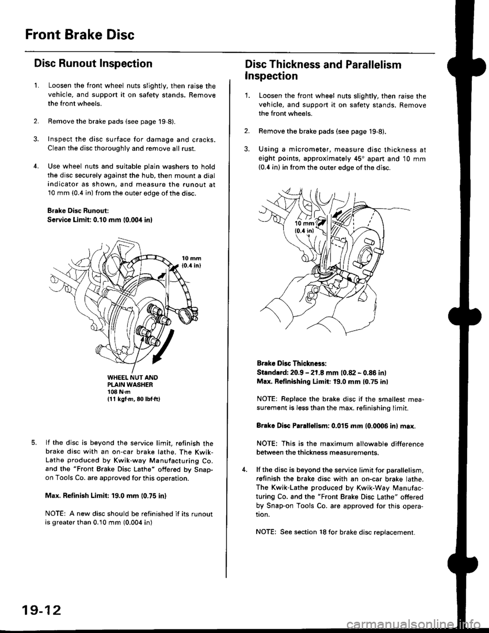
Disc Runout Inspection
L
2.
Loosen the front wheel nuts slightly, then raise the
vehicle, and support it on safety stands. Remove
the front wheels.
Remove the brake pads (see page 19,8).
Inspect the disc surface for damage and cracks.
Clean the disc thoroughly and remove all rust.
Use wheel nuts and suitable plain washers to hold
the disc securely against the hub, then mount a dial
indicator as shown, and measure the runout at
10 mm (0.4 in) from the outer edge of the disc.
Brake Disc Runout:
Service Limit: 0.10 mm (0.004 inl
WHEEL NUT ANOPLAIN WASHER'108 N.m(11 kg{.m, 80 lbf.ft)
lf the disc is beyond the service limit, refinish thebrake disc with an on-car brake lathe, The Kwik-Lathe produced by Kwik-way Manufacturing Co.and the "Front Brake Disc Lathe" offered by Snap-on Tools Co. are approved for this operation.
Max. Refinish Limit: 19.0 mm (0.75 in)
NOTE: A new disc should be refinished if its runout
is greater than 0.10 mm (0.004 in)
19-12
Disc Thickness and Parallelism
Inspection
1.Loosen the front wheel nuts slightly, then raise the
vehicle, and support it on safety stands. Remove
the front wheels.
Remove the brake pads (see page 19-8).
Using a micrometer, measure disc thickness at
eight points, approximately 45" apart and 10 mm(0.4 in) in from the outer edge of the disc.
Brake Dbc Thickn6s:
Standlrd: 20.9 - 21.8 mm (0.82 - 0.86 in)
Max. Refinishing Limit: 19.0 mm 10.75 inl
NOTE: Replace the brake disc if the smallest mea-
surement is less than the max. refinishinq limit.
Brake Disc Parallelism: 0.015 mm (0.fit06 in) max.
NOTE: This is the maximum allowable difference
between the thickness measurements.
lf the disc is beyond the service limit for parallelism,
refinish the brake disc with an on-car brake lathe.
The Kwik-Lathe produced by Kwik-Way Manufac-
turing Co. and the "Front Brake Disc Lathe" offered
by Snap-on Tools Co. are approved for this opera-
tion.
NOTE: See section 18 for brake disc reDlacement.
Page 1178 of 2189

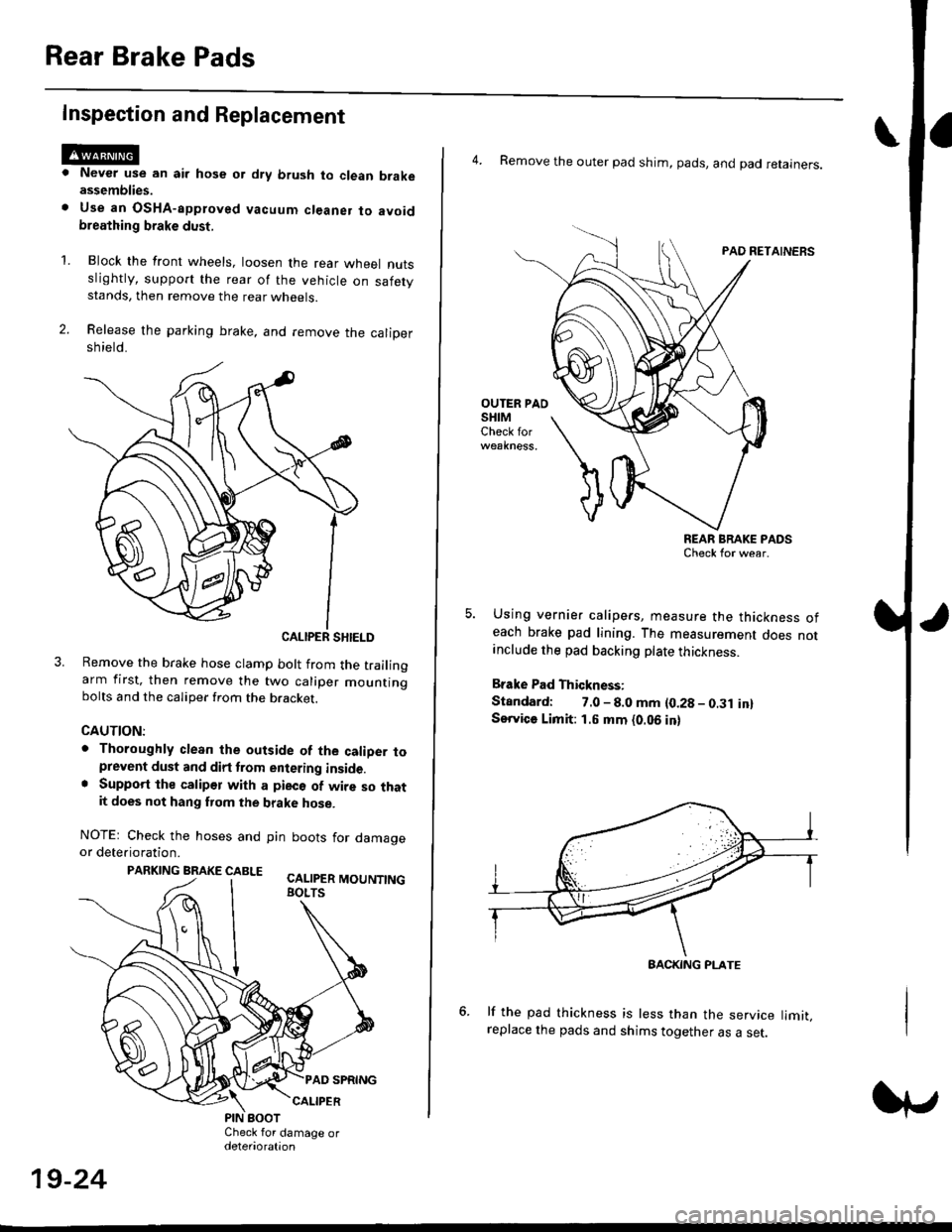
Rear Brake Pads
Inspection and Replacement
Never use an air hose or dry brush to clean brakeassemblies.
Use an OsHA-apptoved vacuum cl€aner to avoidbreathing brake dust,
Block the front wheels, loosen the rear wneet nutsslightly, support the rear of the vehicle on safetystands, then remove the rear wheels.
Release the parking brake, and remove the calioersh ield.
CALIPER SHIELD
Remove the brake hose clamp bolt from the trailingarm first, then remove the two caliper mountingbolts and the caliper from the bracket.
CAUTION:
. Thoroughly clean the outside of the caliDer toprevent dust and dirt trom entering inside.. Support the calipor with a pieco of wire so thatit does not hang fuom the brake hose.
NOTEr Check the hoses and pin boots for damageor deterioration.
PARKING BRAKE CABLE ^.. ._-_ ---.
'L
19-24
4. Remove the outer pad shim, pads, and pad retainers.
PAO RETAINERS
OUTER PAOSHIMCheck for
REAR BRAKE PADSCheck for wear.
Using vernier calipers, measure the thickness ofeach brake pad lining. The measurement does notanclude the pad backing plate thickness.
Brake Pad Thickness:
Standard: 7.0 - 8.0 mm {0.28 - 0.31 in}Service Limit: 1.5 mm {0.06 in}
lf the pad thickness is less than the service limit,replace the pads and shims together as a set.
BACKING PI-ATE
Page 1180 of 2189

Rear Brake Disc
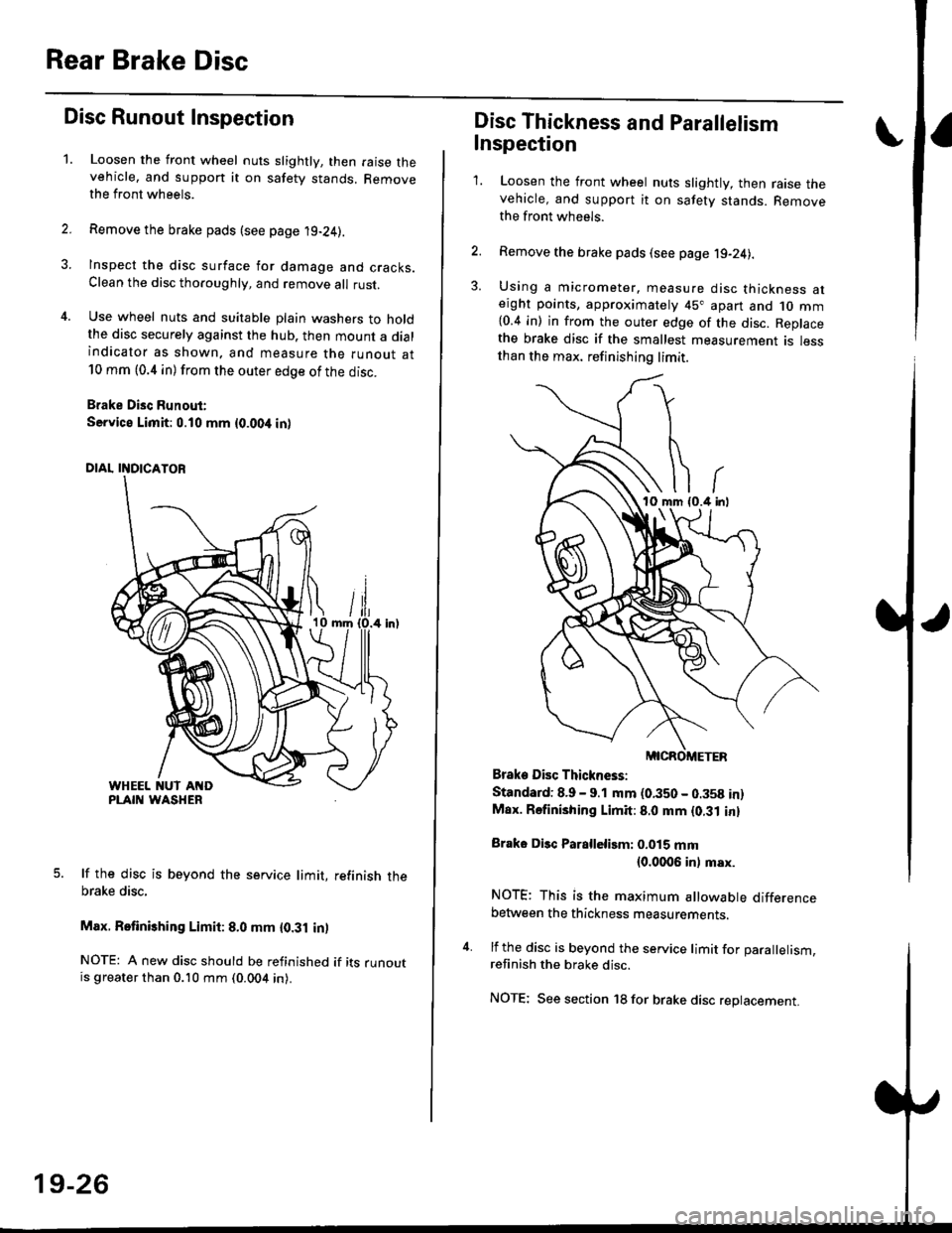
Disc Runout Inspection
1.Loosen the front wheel nuts slightly, then raise thevehicle, and suppon it on safety stands. Removethe front wheels.
Remove the brake pads (see page 19-24).
Inspect the disc surface for damage and cracks.Clean the disc thoaoughly, and remove a
rust.
Use wheel nuts and suitable plain washers to holdthe disc securely against the hub. then mount a dialindicator as shown. and measure the runout at10 mm (0.4 in) from the outer edge of the disc.
Brake Disc Runout:
Service Limit:0.10 mm {0.00,t in)
5. lf the disc is beyond the service limit, refinish thebrake disc,
Max. Retinishing Limit: 8.0 mm {0.31 in)
NOTE: A new disc should be refinished if its runoutis greater than 0.10 mm (0.004 in).
19-26
Disc Thickness and Parallelism
Inspection
1. Loosen the front wheel nuts slightly, then raise thevehicle, and support it on safety stands. Removethe front wh6els.
2. Remove the brake pads (see page j9-24).
3. Using a micrometer. measure disc thickness aterght points, approximately 45" apart and 1o mm{0.4 in) in from the outer edge of the disc. Replacethe brake disc if the smallest measurement is lessthan the max. refinishing limit.
Brake Disc Thickness:
Standard: 8.9 - 9.1 mm (0.350 - 0.358 in)Max. Rsfinishing Limit: 8.0 mm {0.31 in}
Brake Disc Parallelirm: 0.015 mm(0.0006 inl msx.
NOTE; This is the maximum allowable differencebetween the thickness measurements.
4. lf the disc is beyond the service limit for Darallelism.refinish the brake disc.
NOTE; See section 18 for brake disc replacement.
Page 1190 of 2189
Rear Drum Brake
Inspection
1.
4.
Check the wheel cylinder for leakage.
Check the brake linings for cracking, glazing, wear,
and contamination.
Measure the brake lining thickness.
Brake Lining Thickness:
Standard: 4.0 mm {0.157 in}
Service Limit: 2.0 mm 10.08 in)
NOTE; Measurement does not include brake shoe
thickness.
lf the brake lining thickness is less than the service
limit, replace the brake shoes as a set.
Check the bearings in the hub unit for smooth oper-
ation. lf defective, refer to section 18
WHEEL CYLINDER
LININGS
19-36
6. Measure the inside diameter oJ the brake drum
using the inside vernier calipers.
Drum Inside Diameter:
Standard: 199.9 - 200.0 mm {7.870 - 7.874 in)
Servic€ Limit: 201.0 mm (7.913 inl
lf the inside diameter of the brake drum is more
than the service limit, replace the brake drum.
Check the brake drum for scoring, grooves, and
cracks.
7.
8.
INSIDE VERNIER CALIPERS
BRAKE ORUM
Page 1193 of 2189

Brake Hoses/Lines
LJ
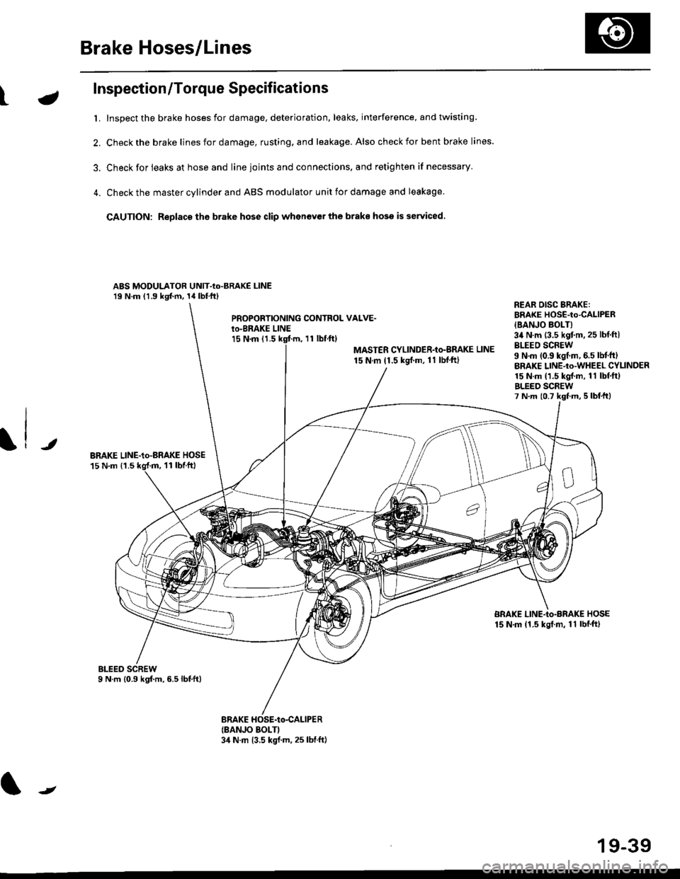
Inspection/Torque Specifications
t. Inspect the brake hoses for damage, deterioration, leaks, interference, and twisting.
2. Check the brake lines for damage, rusting. and leakage. Also check for bent brake lines.
3. Check for ieaks at hose and line ioints and connections, and retighten if necessary'
4. Check the master cylinder and ABS modulator unit for damage and leakage
CAUTION: Replace tho brake hose clip whenev€r the brake hose is serviced.
ABS MODULATOR UNIT-Io-BRAKE l-lNE19 N.m (1.9 kgf.m, 14lbl.ftl
PROPOBTIONING CONTROL VALVE.io-BRAKE LINEl5 N.m (1.511 tbf.ftl
MASTER CYLINDER-Io-BMKE LINE
15 N.m (1.5 ksrf.m, 11 lbf'ft)
REAR DISG BRAKE:BRAKE HOSE-to4ALlPER
{BANJO BOLT}34 N.m (3.5 kgtm,25 lbf ftlBLEEO SCREW9 N'm (0.9 kgf.m, 6.5 lM.ftlBRAKE LINE-to-WHEEL CYLINDER15 N.m (1.5 kgl.m, 11 lbf.ftlBLEED SCREW7 N.m {0.7 kst m, 5 lbf,ttl
JBRAKE LINE-io-aRAKE HOSE15 N.m {1.511 tbtft)
BRAKE LINE-Io-BRAKE HOSE15 N.m (1.5 kgt.m, 11 lbf'ft)
(BANJO BOLT}3,1 N.m 13.5 kgf.m, 25 lbf.ft)
J
19-39
Page 1197 of 2189
Special Tools
Ret. No. I Tool Number I Description I O,V I page Reference
(!) I 07PM- 0010100 I SCS Service Connector t I 19_s6
19-44
Page 1198 of 2189
Component Locations
ta
SERVICE CHECK CONNECTOR {2PIBIGHT.REAR WHEELSENSOR CONNECTORMOOULATOR UNITABS CONTROL UNIT
RIGHT-REAR WHEEL SENSOR
LEFT.R€AR WHEELSENSOR CONNECTOR
J
UNDER.DASH FUSE/RELAY 8OX
LEFT.FRONT WHEEL SENSOR
ABS +B (20 A) FUSE
UNDER.HOOD FUSE/RELAY BOX
lcl lilo Al FUSE
ABS INDICATOR LIGHT
UNOEF.DASI{ FUSE/RELAY BOX
HORN/STOP I15 A) FUSE
UNDER.HOOO ABS FUSE/RELAY BOX
PUMP MOTOR {'O A} FUSE
PUMP MOTOR BELAY
E
o
METEB I7.5 AI FUSE
0
0
0
00000 n
00000 u
BR DEF RLY 17,5 A) FUSE
t
MTR CHECK (7.5 AI FUSE
19-45
Page 1204 of 2189
tABS CONIROL UN]TECM / PCMISCS'
V
,,, +-{l-, ?,,] B6li! [,b.,,,,,-F-
SENSOR
+B
YWHTNED
8U(
J-
G,Ol, Ga02
l
\EWIK
LEFT.
RIGHT,
LEFT
;___.|-1
**1. ,I
coierou
SERVICE CHECKCONNECTOR (2P}
lrl2f
OATA LINKCONNECTOR O 6P)
WHEEL SENSOR2P CONNECTOB
FRONT
/.[Ttl\
REAR
tc-T-lI zlr[B'1213
ABS CONTROL UNIT 26P CONNECTOR1O numb€r)
12346/8Il0./ tt12r3
14 t516 1719 ,/2123
-o&"^1'
cot, croz
Terminalside ofmale terminals
ABS CONTROL UNIT 22P CONNECTOR1! numb€r)
/Wire side of female terminals
19-51