Page 1059 of 2189
Component Locations
tlndex
Manual Steering
NOTE:
. lf an intact airbag assembly has been removed from a scrapped vehicle or has been found defective or damaged dur-
ing transit. storage or service, it should be deployed (see section 24)'
o Before removing the gearbox, remove the driver's airbag assembly and steering wheel
. After insta lling the gearbox, check the wheel alignmentand adjust if necessary
SRS components are located in this area. Review the SRS component locations, precautions, and procedures in the SRS
section 124) before performing repairs or service'
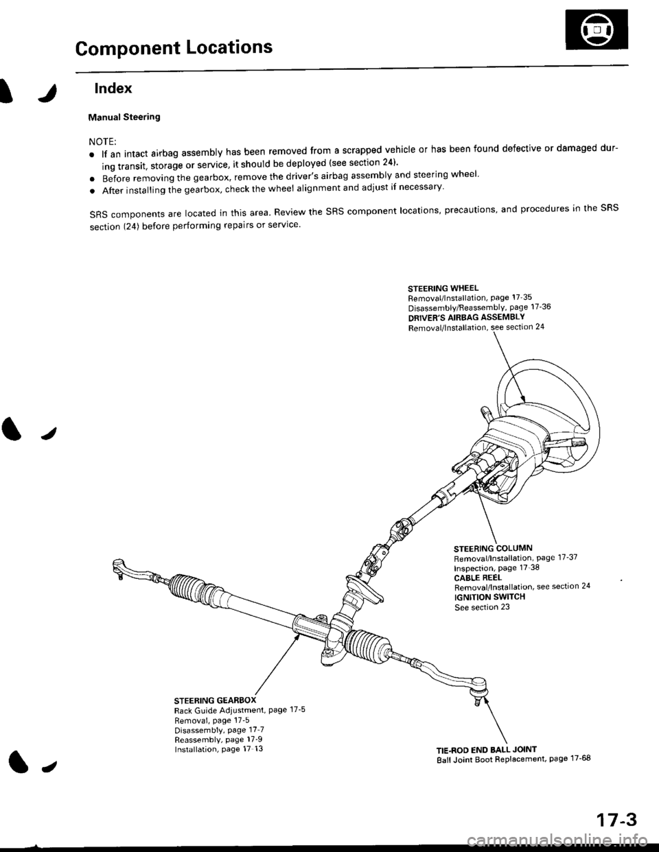
STEERING WHEELRemoval/lnstallation, Page 17'35
Disassembly/FeassemblY, page 17-36
DRIVER'S AIRBAG ASSEMBLY
Removal/lnstallation, see section 24
STEERING COLUMNRemoval/lnstallation, Page 17-37
Inspection, page 17'38
CABLE REELRemoval/lnstallation, see section 24
IGNTTION SWITCH
See section 23
STEERING GEARBOXRack Guide Adiustment, Page 17-5
Removai, page 17'5Disassembly, Page 17_7Reassembly, page 17_9Installation, page 17 13TIE.ROD END BALL JOINT
Ball Joint Boot Replacement, page 17-68
J
t,
17-3
Page 1071 of 2189
Component Locations
I
lndex
Power Steering:
NOTE:
. li an intact airbag assembly has been removed trom a scrapped vehicle or has been found defective or damaged dur-
ing transit. storage or service, it should be deployed (see section 24).
. Before removing the gearbox, remove the driver's airbag assembly and steering wheel.
. After installing the gearbox, checkthewheel alignmentand adjust if necessary.
SRS components are located in this area. Review the SRS component locations. precautions, and procedures in the SRS
section {24} before performing repairs or service.
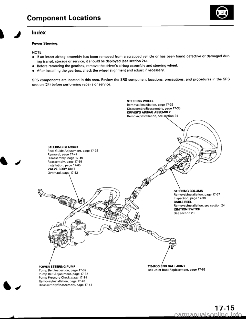
STEERING WHEELRemoval/lnstallation, page 17-35
Disassembly/Feassembly, page 17-36
DRIVER'S AIRBAG ASSEMBLYRemoval/lnstallation, see section 24
STEERING GEAREOXRack Guide Adiustment, page 17'33
/
Removal, page 17 47Disassembly, page 17-49Reassembly, page 17-55Installation, page 17-65VALVE EODY UNITOverhaul, page 17 52
COLUMNFemoval/lnstallation, page 17-37Inspection, page 17-38CASLE REELRemoval/lnstallation, see section 24
IGNITION SWITCHSee section 23
POWEF STEERING PUMPPump Belt Inspection, page 11-32Pump Belt Adiustmenl, page 11'32Pump Pressure Check, page 17 34Removal/lnstallation, page 17'40Disassembly/Reassembly, page 17-41
TIE.ROD END BALL JOINTBallJoint Boot Replacement, page 17-68
1,,
17-15
Page 1080 of 2189
Troubleshooting
General Troubleshooting (cont'd)
Assist (excessively light steering) athigh speed.
Shock or vibration when wheel isturned to {ull lock.
Steering wheelwill not returnsmoothly.
lf the problem is not corrected byadiusting the rack guide, adjustthe front wheel alignment lseesection 181.
Check the rack guide for properadiustment (see page 17 33).
Check the rack guide for properadjustment (see page 17-33).
Rack guide is adjusted properly.
lfthe problem is not corrected byadjusting the rack guide, replacethe gearbox.Check the belt for slippage andaolust as necessary {see page11 32).
A and B cylinder lines are nor-mal, check wheel alignment (seesection 18).
Wheel alignment is abnormal,adjust as needed.
Wheel alignment is normal.Check the steering wheel opera-tion and power assist check {seepage lT-30).
It the measurements are out ofspecifications, adjust the ra ckguide.
lf the problem is not corrected byadjusting the rack guide, replacethe gearbox.
17-24
Page 1125 of 2189
)
Suspension
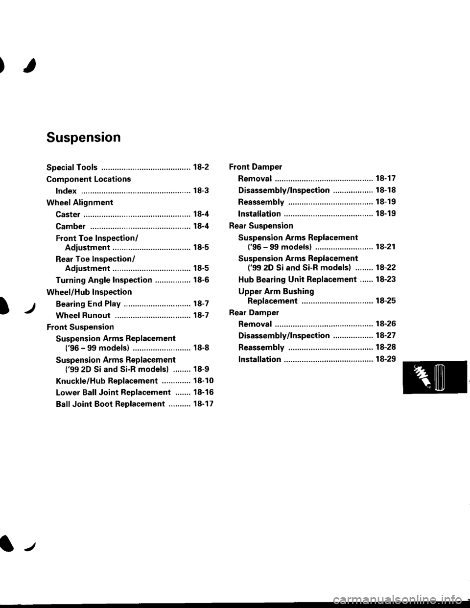
Special Tools ............. 18-2
Component Locations
lndex ,,.............. ...... f8-3
Wheel Alignment
Caster .............. ....... 18-4
Camber .................. l8-4
Front Toe Inspection/
Adiustment ........ 18-5
Rear Toe lnspection/
Adiustment ........ 18-5
Turning Angle Inspection ................ 18-6
Wheel/Hub Inspection
Bearing End P|ay .............................. l8-7
Wheel Runout ....... 18-7
Front Suspension
Suspension Arms Replacement
('96 - 99 modelsl .......................... 18-8
Suspension Arms Replacement
('99 2D Si and Si-R models) ........ 18-9
Knuckle/Hub Replacement ............. 18-10
Lower Ball Joint Replacement ....... 18-16
Ball Joint Boot Replacement .......... 18-17
Front Damper
Removal ................. 18-17
Disassembly/1nspection .................. 18-18
Reassembly ........... 18-19
lnstallation ............. 18-19
Rear Suspension
Suspension Arms Replacement
('96 - 99 models) ....................,..... 18-21
Suspension Arms Replacement
('99 2D Si and Si-R models) ........ 1A-22
Hub Bearing Unit Replacement ...... 18-23
Upper Arm Eushing
Replacement .....18-25
Rear Damper
Removal ................. 18-26
Disassembly/|nspection ............. ..... 1A-27
Reassembly ........... 18-28
lnstallation ............. 18-29
lr
Page 1127 of 2189
Component Locations
)
lndex
Wheel Alignment, page l8 4
FBONT DAMPER. Removal, page 18-17. Disassembly/lnspection, page 18-18. Reassembly, page 18'19. Installation, page 18-19
KNUCKLE/HUB. Replacement, page 18'10
Front Suspension:
Rear Suspsnsion:
UPPER ARM' Replscement, page 18-8
. Wheel Bearing Replacement, page 18-14. Lower EallJoint Replacement, page 18-16STABILIZER BAR' Replacement, page 18-8
LOWER ARM. Replacement, Page 18-8
UPPER ARM' Replacement, page 18 20
LOWER ARM. Replacement, page 18-20
REAR DAMPEB. Removai. page 18-26. Disassembly/lnspection, page 18-27. Feassembly, page lS-28. Installation, page 18-29
ARMTRAILING ARM' Replacement, page 18-20l-,. Feplacement, page 18 20
18-3
Page 1128 of 2189
Wheel Alignment
,f,
Caster
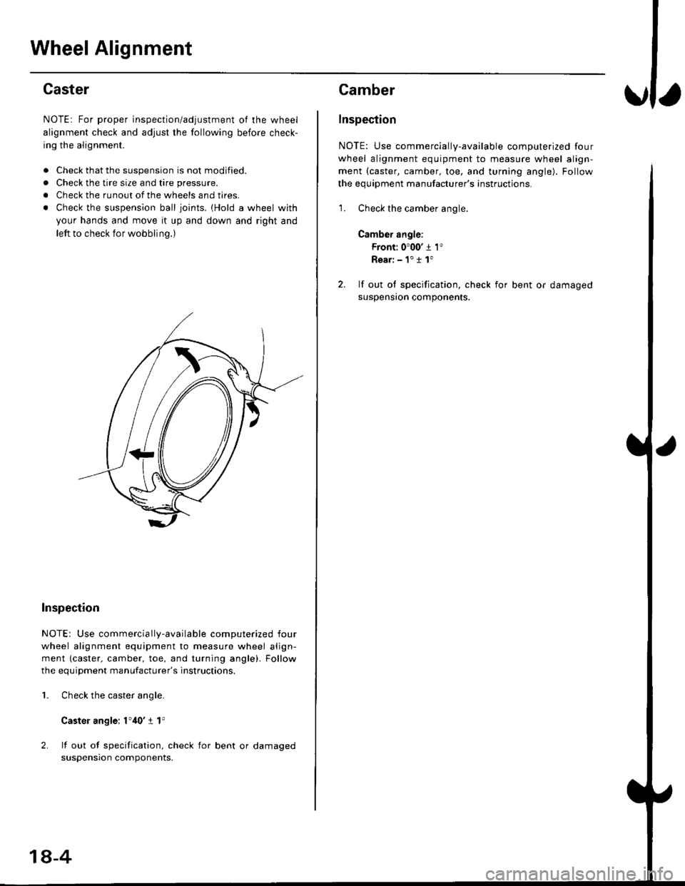
NOTE: For proper inspection/adjustment of the wheel
alignment check and adjust the following before check-
ing the alignment.
. Check that the suspension is not modified.
. Check the tire size and tire pressure.
. Check the runout of the wheels and tires.
. Check the suspension ball ioints. {Hold a wheel with
your hands and move it up and down and right and
left to check for wobbling.)
Inspection
NOTE: Use commercia lly-available computerized four
wheel alignment equipment to measure wheel align-
ment {caster. camber, toe, and turning angle). Follow
the equiDment manufacturer's instructions.
Check the caster angle.
Caster angle: 1',10' I 1'
lf out of specification, check for bent or damaged
suspensron components.
2.
1.
18-4
Camber
lnspection
NOTE: Use commercially-available computerized four
wheel alignment equipment to measure wheel align-
ment (caster, camber, toe, and turning angle). Follow
the equipment manufacturer's instructions.
1. Check the camber angle.
Camber angle:
Front: 0'00' j 1"
Rear:-1"11"
2. lf out ol specification, check for bent or damaged
suspensron components.
Page 1129 of 2189
?
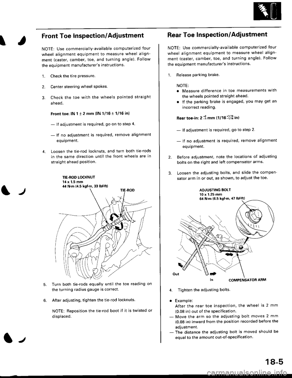
Front Toe Inspection/Adiustment
NOTE: Use commercially-available computerized four
wheel alignment equipment to measure wheel align-
ment (caster, camber, toe, and turning angle). Follow
the equipment manufacturer's instructions.
1. Check the tire pressure.
Center steering wheel spokes.
Check the toe with the wheels pointed straight
a head.
Front toe: lN 1 1 2 mm llN l/16 r 1/16 inl
- lf adjustment is required, go on to step 4.
- lf no adjustment is required, remove alignment
equrpmenr.
Loosen the tie-rod locknuts, and turn both tie-rods
in the same direction until the front wheels are in
straight ahead position.
TIE.ROD LOCKNUT'14 x 1.5 mm
4.
tJ
6.
Turn both tie-rods equally until the toe readang on
the turning radius gauge is correct.
After adjusting, tighten the tie-rod locknuts.
NOTE: Reposition the tie-rod boot if it is twisted or
displaced.
4,1 N.m {4.5 kgf.m, 33 lb{.ft)
2.
Rear Toe Inspection/Adiustment
NOTE: Use commercially-available computerjzed Iour
wheel alignment equjpment to measure wheel align-
ment (caster, camber, toe, and turning angle). Follow
the equipment manufacturer's instructions.
1. Release parking brake.
NOTE:
a Measure difference in toe measurements wlth
the wheels pointed straight ahead.
. if the parking brake is engaged, you may get an
incorrect readang,
Rear toe-in: 2 11 mm ttltollllS int
- lf adjustment is required, go to step 2.
- lf no adjustment is required, remove alignment
equipment.
Before adjustment, note the locations of adiusting
bolts on the right and left compensator arms
Loosen the adjusting bolts, and slide the compen
sator arm in or out. as shown, to adjust the toe
ADJUSTING BOLT10 x 1.25 mm
In CoMPENSAToR ARM
4. Tighten the adiusting bolts
. Example:
After the rear toe inspection, the wheel is 2 mm
(0.08 in) out of the specification.- Move the arm so the adjusfing bolt moves 2 mm
(0.08 in) inward trom the position recorded before the
adjustment.- The distance the adjusting bolt is moved should be
equal to the amount out-of-specification.
64 N.m 16.5 ksf m, 47 lbtft)
18-5
Page 1130 of 2189
Wheel Alignment
Turning Angle Inspection
NOTEr Use commercially-available computerized four
wheel alignment equipment to measure wheel align-
ment (caster, camber, toe, and turning angle). Follow
the equipment manufacturer's instructions.
'1. Turn the wheel right and left while applying the
brake, and measure the turning angle of both
wneets.
Turning angle:
lnward wheel: 39'50'
Outwald wheel (ref erencel: 33'10'
2.lf the turning angle
check for bent or
nents,
is not within the specifications,
da m aged suspension compo-
18-6