2000 HONDA CIVIC service reset
[x] Cancel search: service resetPage 525 of 2189

Emission Control System
Exhaust Gas Recirculation (EGR) System (D16Y5 engine with GWI (cont'dl
lTl49il T_he scan tool indicates Diagnostic Trouble Code (OTC) P1491: A malfunction in the Exhaust Gas Recirculation- lEgh) svstem.
CvT lM/T see page 1l-2611:
J
EGR VALVELIFT SENSOR#16 HOSE
PUMP/GAUGE,0- 30 in.HsA973X-041-XXXXX
EGRVALVE
The MIL has been reoorted on.DTC P1491 is stoled.
Problem verification:1. Do the ECM/PCM Reset Proce-du re.2. Connect the SCS service con'
3. Start the engine. Hold theengine at 3,000 rpm with noload {in Park or neutral) untilthe radiator fan comes on,4. Drive the vehicle on the roadfor approx. 10 minutes. Try tokeep the engine speed in the1,700 - 2,500 rpm range.
Intermittonl failure, system is OKat this time. Check for Door con-nections or loose wires at, C144{EGR velve} and ECM/PCM.
ls DTC P l49l indicated?
Check fo. vacuum to ihe EGR
1. Disconnect the No. 16 hose fromthe EGR valve.2. Connect a vacuum pump/gauge to the hose.3. Start the engine and let it idle.
ls there any vacuum?
Check tor a malfunction in theEGR control solenoid valve:'1. Disconnect the EGR controlsolenoid valve 2P connector,2. Becheck the No. 16 hose for
Check vacuum hose routing o,the entire EGR svstem. lf hoserouting is OK, replac€ the EGRcontrol solenoidvalv6.
ls there any vacuum?
Substitute a known-good ECM/PCM and recheck. It symptom/indicalion goes away, replacethe original ECM/PCM.
(To page 11 257)
11-256
Page 530 of 2189

\JExhaust Gas Recirculation System (D16Y5 engine with M/T)
M/T:
EGR VALVE 6P CONNECTOB (C14'rl
G10lIBLK}
1
a
PNK
IE.EGRI
Wi16 side of male terminals
I
sG2{GRN/BLK}
vcc2{YEL/BLU)
- Th6 MIL ha3 b€on reponed on.- DTC Pl,{tl is 3tored.
Prcblem verification:1. Do the ECM Reset Procedure.
2. Connect the SCS service con_nector.3. Start the engine. Hold the
engine at 3,000 rpm with no
load (transmission in neutral)
untilthe radiator fan comes on.
4. Drive the vehicle on the road
for approx. 10 minutes. Try to
keep the engine speed in the
1,700 - 2,500 rpm range.
lnlermittont tailure, svalem is OK
at thi3 tim6. Check foi Poor con'
nections or looso wiro3 at Cl/K
IEGR valvsl and ECM.
ls DTC P1491 indicated?
Check tor a malfunction in the
EGR valv6:1. Turn the ignition switch OFF.
2. Disconnect the EGR valve 6P
connector.3. Stanthe engine and let it idle
4. Measure voltage between the
EGR valve 6P connector termi'
nals No.4and No.6.
Check the EGR valve:1. Turn the ignition switch OFF2. Turn the ignition switch ON lll).3. Measure voltage between theEGR valve 6P connector termi
nals No.2 and No.3.
ls there battery voltage?
Substitute a known-good ECM
and recheck. It symptom/indica_tion goes away, replace th€ origi-
nal ECM.
ls there approx.5V?
(To page 11-262)
Page 540 of 2189

\J
\
,96 D16Y5 engine,,96 D16r,gngino,,96 Dt6Y8 engine {3edan)' 37 D16Y5 engino..97 D16r, engine {coupe: KA, Kc mod-
els. sedan: KA, KC, KL {DX} models. hatchback: all modols}''97 Dl6Y8 ongine (s€dan: KA' KC mod€lsl:
The scan tool indicates Diagnostic Trouble code (DTC) P0441: Evaporative Emission (EVAP) control system
insufficient purge flow.
Description
By monitoring the purge line vacuum with the MAP sensor, the ECM/PCM can detect insufficient EVAP control system
purge flow.
Possible Cau3e
. EVAP Purge Control Solenoid Valve
. EVAP Purge Control Solenoid Valve Circuit
. EVAP Control Canister
. Vacuum Lines
. ECM/PCM
Troubl93hooting Flowchart
Wire side of femaleterminals
EVAP PURGE CONTROI-sottNotD vALvE 2P
CoNNECTOR (Cl1al
r-+-r
I'l'l
lG-ro.*l'rr"r
O)
Y
(cont'd)
11-271
- The MIL has bsGn.eportad on.- DTC milal k rtored.
Pioblem vsrificJtion:1. Start the engine. Hold the
engine at 3,000 rPm with no
load {in Park or noutral) until
the radiator fan comes on.
2. Do the ECM/PCM Reset Proce'
dure,3. Connect the SCS service con-
nector.4. Test-drive under following con-
ditions on the road- Without any electrical load- A/T in E or E Position(M/T in 3rd-sth gear)- Engine sPeed betweon
1,200 - 2.400 rpm.- Decelerate {rom 50 mph (80
knl/h)to 15 mph (24 km/h)lntormittont lailuro, sFtorn b OK
at thi. timo. Ch€ck tor Poor con'
ncction3 or looac wir.3 at C144
{EVAP purgo control tolonoid
vrtv.l .nd ECir/FCttl.
ls DTC P0441 indicatod?
Ch.ck fo. !n op€n in the wiro l|(illinel:1. Turn the ignition switch OFF.
2. Disconnect the EVAP Purgecontrol solenoid valve 2P con_
neclor,3. Turn the ignition switch ON (ll)
4. Measur€ voltage between bodyground and the EVAP Purgecontrol solenoid valve 2P con-
nector terminal No 1.
Rop.ir opor in tho wir6 b€two€n
the EVAP purgo codtiol tolonoid
v.lvo rnd tho No 15 ALIERNA'
TOR SP SENSOR 17.5 A)lu.o.
{To page 11-272)
Page 729 of 2189

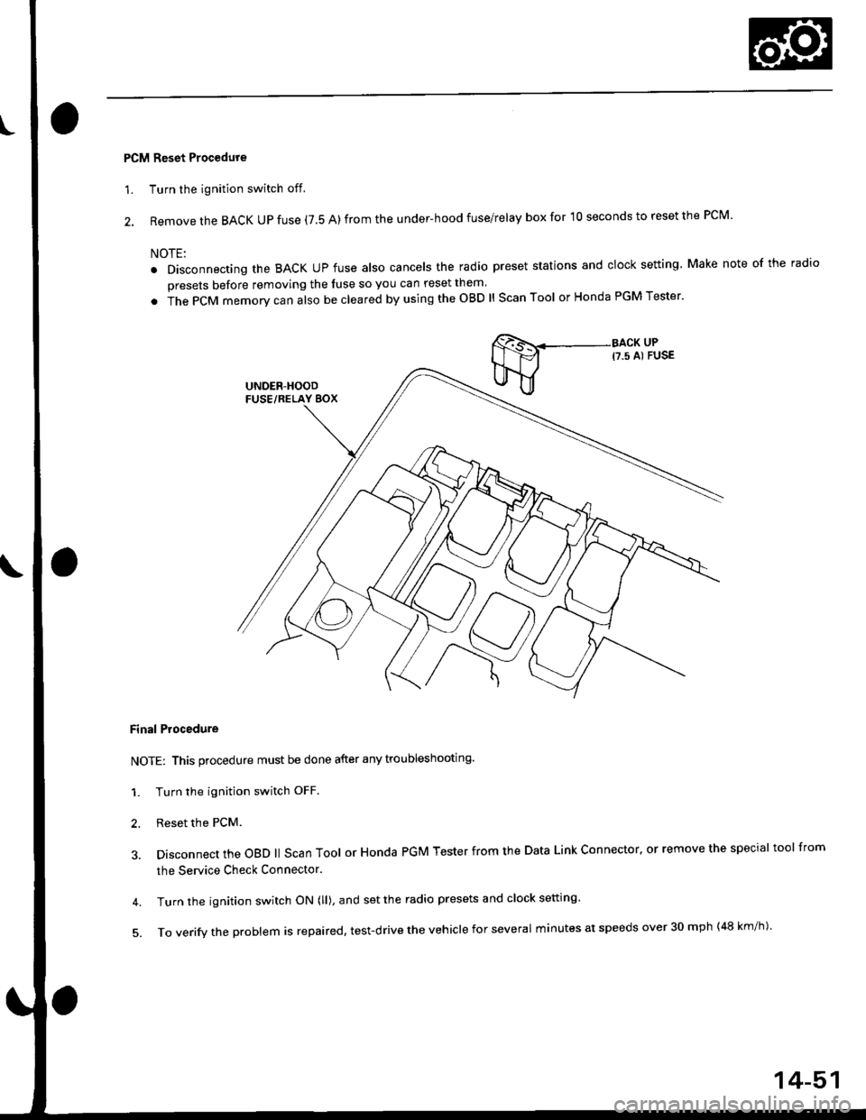
PCM Reset Procedure
1. Turn the ignition switch off.
2. Remove the BACK UP fuse (7.5 A) from the under-hood fuse/relay box for '10 seconds to reset the PCM'
NOTE:
. Disconnecting the BACK UP fuse also cancels the radio preset stations and clock setting Make note of the radio
presets before removing the luse so you can reset them
. in" gCfU memory can also be cleared by using the OBD ll Scan Tool or Honda PGM Tester'
Final Procedure
NOTE: This procedure must be done after any troubleshooting.
1. Turn the ignition switch OFF.
2. Reset the PcM.
3. Disconnect the oBD ll scan Tool or Honda PGM Tester from the Data Link connector, or remove the special tool from
the Service Check Connector.
4. Turn the ignition switch ON (ll), and set the radio presets and clock setting'
5'ToVerifytheprob|emisrepaired,test.drivetheVehic|eforseveralminutesatspeedsover30mph(48km/h).
14-51
Page 753 of 2189

Troubleshooting Flowchart - Shift Control System
NOTE: Record all freeze data before vou troubleshoot.
Possible Cause
Faulty shift control system
. OBD ll Scan Tool indicates CodeP0730.. Sell-diagnosis E indicator
light indicates Code ill.
Check tor Another CoderCheck whether the OBD ll scantool or the E, indicator lightindicate another code.
Perlorm ths TroubleshoolingFlowch.rt for the indic.t.dCode(sl. Recheck tor code m730
l4'l I atter troubleshooting.
Does the oBD ll scan tool orthe E indicato'. tight indicate another code?
Test lst, 2nd, 3rd and 4th Clutch
Pressure:Measure the 1st, 2nd, 3rd and 4th
clutch pressure (see page 14119
thru 14-121).
Ropair the hydrlulic systom !snecessary {see page 14-1 19 and11-1211.
ls each clutch pressure within
the service limit?
Replace Shift Control Solenoidvalve Assembly, Linear SolenoidAssambly and Rechock:1. Replace the shift controlsolenoid valve A'/B assembly(see page 14-106).2. Replace the linear solenoidassembly lsee page 14 108).3. Turn the ignition switch OFFand reset the PCM memory byremoving the EACK UP (7.5 A)tuse in the under hood fuse/relay box for more than l0
seconds,4. Drive the vehicle at over 12mph (20 km/h) in 1st, 2nd,3rd
and 4th gear for more than 30seconds at P1 position.
5. Recheck tor code P0730 (41).
Does the OBD ll scan tool orthe Ed indicator tight indi
cate code P0730 {41)?
The swt6m is OK et this time.
NOTE: Do not continue with this troubleshooting until the causes ot any
other DTCS have been corrected.
Page 777 of 2189

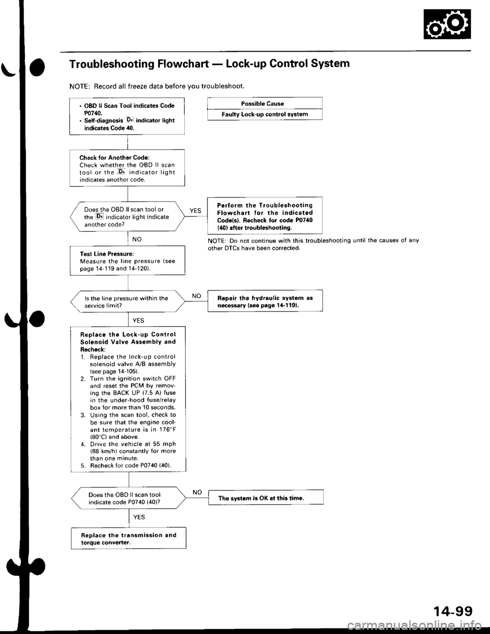
Troubleshooting Flowchart - Lock-up Control System
NOTE: Record all freeze data before vou troubleshoot.
Possibl€ Cause
Faulty Lock-up control sy3tem
NOTE: Do not continue with this troubleshootingother DTCS have been corrected.until the causes of any
OBD ll Scan Tool indicates Codem14/J.S€lf-diagnosis .D4l indicalor lightindicates Code 40.
Check for Another Code:Check whether the OBD ll scantool or the :E indicator lightindicates another code,
Perform the TroubleshootingFlowchart tor the indicatedCodels|. Rocheck to. code P0740(40) .fter troublBhooting.
ooes the OBD ll scan tool orrhe E indicator light indicateanother code?
Test Line Pressure:Measure the line pressure (see
page 14 119 and 14-120).
Repair the hydrrulic sy3tem asn6c6ssary (see page 14-1191.ls the lane pressure within theservice limit?
Replace the Lock-up ControlSolenoid Valve Assembly andRecheck:1. Replace the lock-up controlsolenoid valve A/B assembly(see page 14-105).2. Turn the ignition switch OFFand reset the PCM by removing the EACK UP (7.5 A) fusein the underhood {use/relaybox for more than 10 seconds.3. Using the scan tool, check tobe sure that the engine cool-ant temperature is in 176'F(80'C) and above.4. Drive the vehicle at 55 mph(88 km/h) constantly for morethan one minute,5. Recheck for code P0740 {40).
Does the OBD ll scan toolindicate code P0740 (40)?The svstem i3 OK .t this time.
14-99
Page 778 of 2189

Electrical Troubleshooting ('99 - 00 Modelsl
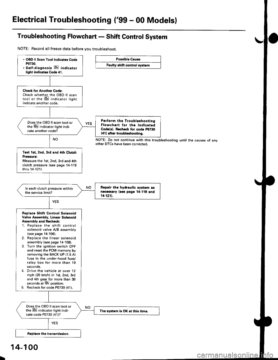
Troubleshooting Flowchart - Shift Control System
NOTE: Record allfreeze data before you troubleshoot.
Po33ibl. Crus6
Frulty 3hift control ryrtom
. OBD ll Scan Tool indicrtd Codem730.. Self-dirgnosis E indicatorlight indicst€. Codo 41.
Check for Anoth€. Code:Check whether the OBD ll scantool or the E indicator lightindicate another code.
Prrf orm tho Troublc!hootingFlowch.rt for th. indicrt.dCod.l3l. R.ch.ck tor cod. m730141| .tt r troubldhootlng.
Doesthe OBD llscan tool orthe E indicator light indi-cate another code?
Test 13t, 2nd, 3rd .nd 4th ClutchPrglture:Measure the 1st, 2nd,3rd and 4thclutch pressure (see page 14-119thru 14 121).
R.prir tho hydrlulic ayrtam aan.c.3t..y lr.o p!9. lil-119 rnd1+1211.
ls each clutch pressure withinthe service limit?
Roplace Shift Control SolenoidValve Asembly. Linoar Sol.noidAssembly .nd Recheck:1. Replace the shift controlsolenoid valve A/B assembly(see page 14-106).2. Replace the linear solenoidassembly {see page 14-108}.3. Turn the ignition switch OFFand reset the PCM memory byremoving the BACK UP (7.5 A)fuse in the under-hood fuse/relay box for more than 10seconds,4. Drive the vehicle at over 12mph (20 kn/h) in 1st, 2nd, 3rdand 4th gear lo. more than 30seconds at lPll position.5. Recheck for code P0730 (41).
Doesthe OBD Ilscan tool orthe E ;ndicator light indi-cate code P0730 (41)?Th. sFtcm b OK .t this time.
NOTE: Do not continue with this lroubleshooting until the causes ot anyother OTCS have beon corrected.
I
14-100
Page 912 of 2189

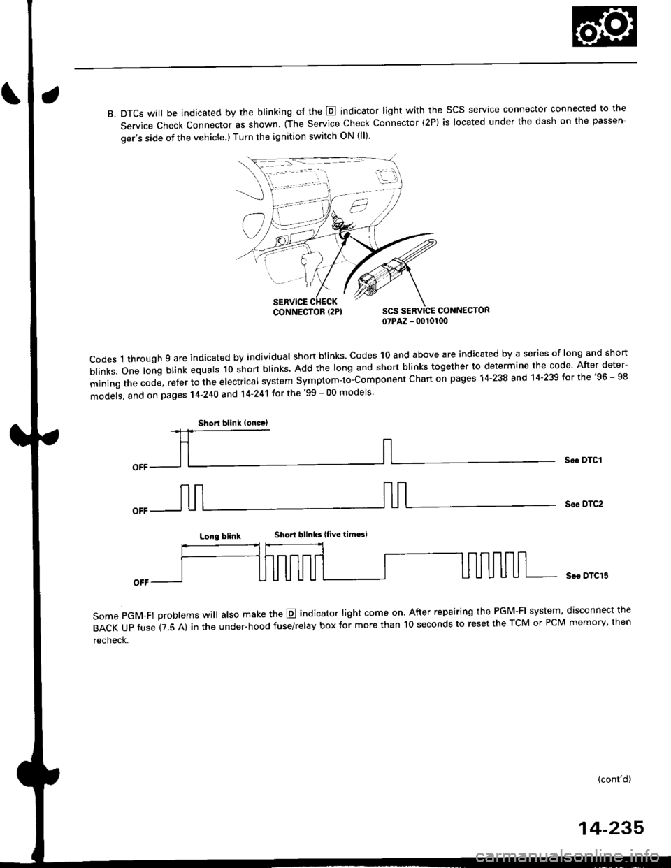
B. DTCS will be indicated by the blinking of the E indicator light with the SCS service connector connected to the
Service Check Connector as shown. (The Service Check Connector (2P) is located under the dash on the passen
ger's side of the vehicle.) Turn the ignition switch ON (ll).
CONNECTOR07PAZ - 00101(x)
codes 1 through 9 are indicated by individual shon btinks. codes 10 and above are indicated by a series of long and short
b|inks.one|ongblinkequa|sloshortb|inks.Addthe|ongandshortb|inkstogethertodeterminethecode.Afterdeter
miningthecode,refertothee|ectrica|systemsymptom-to-componentchartonpagesl4-238and14.239forthe,96_98
models, and on pages 14-240 and 14'241 for the '99 - 00 models
Soc DTCI
Sor DTC2
Long blinkShort blinks |tive tim€sl
some pGM-Ft problems wi
atso make the E indicator light come on. After repairing the PGM-FI system, disconnect the
BACKUPfuse(7.5A)intheUnder.hoodfuse/re|ayboxformorethanl0secondstoresettheTcMorPcMmemory,then
recheck.
Scc DTCI5
(cont'd)
14-235
iii:j
,,,/
CONNECTOR {2PI
Shorl blink (oncc)