Page 1193 of 2189

Brake Hoses/Lines
LJ
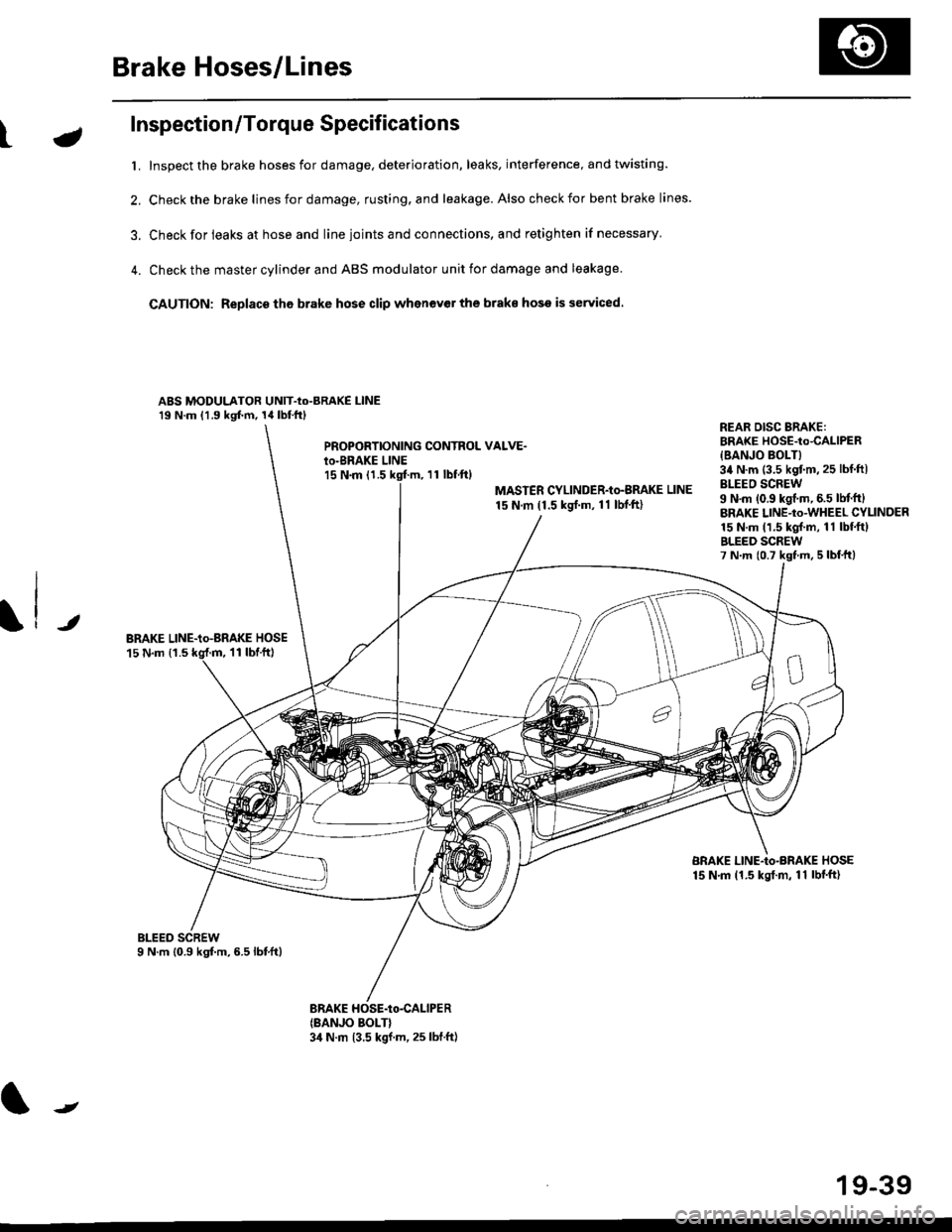
Inspection/Torque Specifications
t. Inspect the brake hoses for damage, deterioration, leaks, interference, and twisting.
2. Check the brake lines for damage, rusting. and leakage. Also check for bent brake lines.
3. Check for ieaks at hose and line ioints and connections, and retighten if necessary'
4. Check the master cylinder and ABS modulator unit for damage and leakage
CAUTION: Replace tho brake hose clip whenev€r the brake hose is serviced.
ABS MODULATOR UNIT-Io-BRAKE l-lNE19 N.m (1.9 kgf.m, 14lbl.ftl
PROPOBTIONING CONTROL VALVE.io-BRAKE LINEl5 N.m (1.511 tbf.ftl
MASTER CYLINDER-Io-BMKE LINE
15 N.m (1.5 ksrf.m, 11 lbf'ft)
REAR DISG BRAKE:BRAKE HOSE-to4ALlPER
{BANJO BOLT}34 N.m (3.5 kgtm,25 lbf ftlBLEEO SCREW9 N'm (0.9 kgf.m, 6.5 lM.ftlBRAKE LINE-to-WHEEL CYLINDER15 N.m (1.5 kgl.m, 11 lbf.ftlBLEED SCREW7 N.m {0.7 kst m, 5 lbf,ttl
JBRAKE LINE-io-aRAKE HOSE15 N.m {1.511 tbtft)
BRAKE LINE-Io-BRAKE HOSE15 N.m (1.5 kgt.m, 11 lbf'ft)
(BANJO BOLT}3,1 N.m 13.5 kgf.m, 25 lbf.ft)
J
19-39
Page 1201 of 2189

Anti-lock Brake System {ABS)
Operation (cont'dl
ABS Modulator
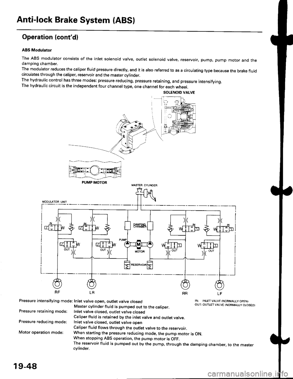
The ABS modulator consists of the inlet solenoid valve, outlet solenoid valve, reservoir, pump, pump motor and thedamping chamber.
The modulator reduces the caliper fluid pressure directly, and it is also referred to as a circulating type because the brake fluidcirculates through the caliper, reservoir and the master cylinder.The hydraulic control has three modes: pressure reducing, pressure retaining, and pressure intensifying.The hydraulic circuit is the independent four channel type, one channel for each wheel.
RF LR
Pressure intensifying mode: Inlet valve open, outlet valve closed
Pressure retaining mode:
Pressure reducing mode:
Motor operation mode:
rN: INLETVALVE {NORMALtY OpENIOUT: OUTIET VALVE {NORMALIY CTOSED)Master cylinder fluid is pumped out to the caliDer.Inlet valve closed, outlet valve closedCaliper fluid is retained by the inlet valve and outlet valve.Inlet valve closed, outlet valve oDenCaliper fluid flows through the outlet valve to the reservoir.When starting the pressure reducing mode, the pump motor is ON.When stopping ABS operation, the pump motor is OFF.The reservoir fluid is pumped out by the pump, through the damping chamber, to the mastercvlinder.
PUMP MOTOR
19-48
Page 1208 of 2189

tJ
t\
Kickback
1. The motor operates when the ABS is functioning, and the fluid in the reservoir is forced out to the master cylinder
causing kickback at the brake pedal.
2. TheABScontrol unit operates the solenoid valve when the brake pedal is released afterthe initial diagnosis Youmay
hear the faint solenoid valve operation sound at this time. but it is normal.
Pump Motor
1. The pump motor operates when the ABS is functioning
2. The ABS control unit checks the pump motor operation during acceleration. You may hear the faint operation sound
at this time. but it is normal.
Brake Fluid Replacament/Air Blsading
1. Brake fluid replacement and air bleeding procedures are the same as for conventional brakes
Troubleshooting
1. The troubleshooting flowcharts explain the procedures on the assumption that the cause of the problem is still pre-
sent and the ABS indicator light is still on.
Note that troubleshooting following the flowchart when the ABS indicator light does not come on can result in incor-
rect judgment.
2. Ouestion the customer about the conditions when the problem occurred, and try to reproduce the same conditions
for troubleshooting.
self,diagnosis is made at various times such as the initial diagnosis, except ABS control. during ABS control, during
acceleraiion, during the specified vehicle speed, etc. Therefore, the symptom cannot be checked unless the check
conditions match with the problem conditions
3. When the ABS indicator light does not come on during the test drive, but the troubleshooting is performed based on
the DTC, check for the loose connectors. poor contact of the terminals, etc, before troubleshooting.
4. After troubleshooting, erase the DTC and test-drive the car. Be sure that the ABS indicator light does not come on.
5. The connector illustrations show the female connectors with a single outline and the male connectors with a double
ouflrne.
6. The connector terminal cavities containing female terminals are always numbered by looking at the connector from
the wire side. and the cavities containing male terminals are always numbered by looking at the connector from the
terminal side.
r'
19-55
Page 1233 of 2189
l}
GLASSReplacement,page 20 6Adiustment,page 20-20GLASS RUNCHANNEL
CENTER LOWERCHANNEL
eCYLINDERPBOTECTORREGULATORReplacement,page 20-6LOCK RODPROTECTOR
STRIKER 'Adjustment, llpage 20-23
tt t[
#-l|r&
/h)
/Y
LATCHReplacement,20-6
LOCKCYLINOERRETAINERCLIP
^o
?'2'
ourER HANoLE
ecuLaron
HANOLE
POWER DOORLOCK SwlTCH(driver's only)
Replacement, page 20-5
INNEN HANDLE ROD
LATCHPROIECTOR
-) /
s/
*Nqd'
/ -"-/
tt\
. '\
It
INNERHANDLE
20-3
Page 1235 of 2189
\:Outer Handle Replacement
NOTE: Raise the glass fully.
'1. Remove:
. Door panel
. Plastic cover (see page 2o-21
2. Pull out the retainer cliP.
6x1.omm Ii.e N.. tr.o rgf.-, I7.2 rbr.fi) ,2
C3.
CYLINDER PROTECTOR
LOCK CYLINDEB
RETAINERCLIP
Remove the bolts, then remove the cylinder protec-
tor, lock cylinder and outer handle.
>: Bolt locaiions,2
CYLINDER
LOCK CYLINDER
CYLINDER ROD
20-5
4. Pull out the outer handle. Pry the outer handle rod
out of its joint using diagonal cutters
NOTE:
a To ease reassembly, note location @ of the outer
handle rod on the joint before disconnecting it.
. Take care not to bend the outer handle rod.
o Use a shop towel to protect the opening in the
ooor.
OUTER HANDLEROD
DIAGONALCUTTERS
SHOPTOWEL
lnstallation is the reverse of the removal procedure
NOTE: Make sure the door locks and opens properly.
BUSHINGReplace.
\
,w.
5.
i4'
Page 1236 of 2189

Doors
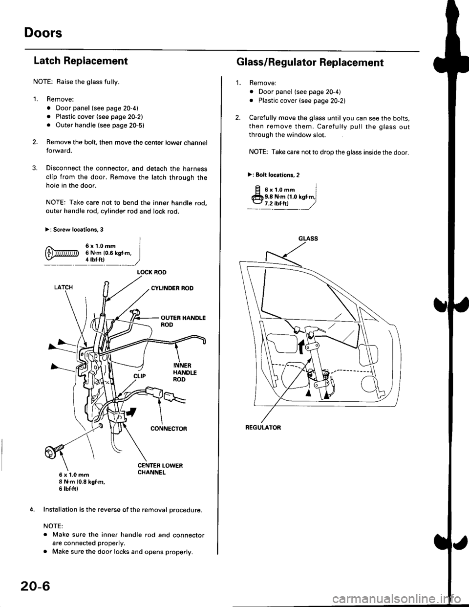
Latch Replacement
NOTE: Baise the glass fully.
1. Remove:
. Door panel (see page 20-4)
. Plastic cover (see page 20-2). Outer handle (see page 20-5)
Remove the bolt, then move the center lower channel
forwa rd.
Disconnect the connector, and detach the harness
clip from the door. Bemove the latch through the
hole in the door.
NOTE: Take care not to bend the inner handle rod,
outer handle rod, cylinder rod and lock rod.
>: Screw locations, 3
6 x 't.0 mm8 N.m (0.8 kgt m,6 tbf.ftl
4. Installation is the reverse of the removal procedure.
NOTE:
. Make sure the inner handle rod and connector
are connected properly.
. Make sure the door locks and opens properly.
LOCK ROO
20-6
'1.
Glass/Regulator Replacement
Removel
o Door panel (see page 20-4)
. Plastic cover (see page 20-2l,
Carefully move the glass until you can see the bolts,
then remove them. Carefully pull the glass out
through the window slot.
NOTE: Take care not to drop the glass inside the door.
>i Bolt loc.tions,2
fi s'r.o-. iClb9.8 N.m 11.0 kst m,l
_-l't!!t ,/
GLASS
REGULATOR
Page 1245 of 2189
?
GLASSReplacement,page 20-19Adjustment,page 20-20
GLASS RUNCHANNEL
3ill,'^lri"*'"tt--.-.qq
\,
\I\\II REGULATOR
\ neptacement, page zo rs
\'l 6
trq\ v.
CYLINDERPROTECTOR
tr
POWERMOTOR
LATCHReplacement,page 20-18
STRIKERAdjustment,page 20-23
\
fitn
\a\.vqE
LOCKCYLINDER
RETAINEBCLIP
BOD PROTECTOR
INNER HANDLE ROD
LATCHPROTECTOR
20-15
Page 1247 of 2189
bOuter Handle Replacement
NOTE: Raise the glass fully.
1. Remove:
. Door panel
. Plastic cover (see page 20-14)
2. Pull out the retainer clip.
3.e\
CYLINOER PROTECTOR
LOCK CYLINDER
RETAINERCLIP
Remove the bolts, then remove the cylinder protec-
tor, lock cylinder and outer handle.
>: Bolt locations,2
6x1.omm ]9.8 N.m {1.0 kgf.m,1.2tbl,ttl )_, _-_-,/
CYLINDERPROTECTOR
LOCK CYLINOER
CYLINOER ROD
20-17
4. Pull out the outer handle. Pry the outer handle rod
out of its joint using diagonal cutters.
NOTE:
. To ease reassembly, note location @ ot the outer
handle rod on the joint before disconnecting it.
. Take care not to bend the outer handle rod.
. Use a shop towel to protect the opening in the
door.
DIAGONALCUTTERS
SHOPTOWEL
5. Installation is the reverse of the removal procedure.
NOTE: Make sure the door locks and opens properly.
EUSHINGReplace.
\
,pr,