Page 1176 of 2189
Master Cylinder/Brake Booster
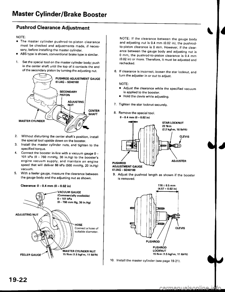
Pushrod Glearance Adjustment
NOTEr
. The master cylinder pushrod-to-piston clearancemust be checked and adjustments made, if neces_sary, before installing the master cylinder.. ABS type is shown, conventional brake type is similar.
1. Set the special tool on the master cylinde. body; push
in the center shaft until the top of it contacts the endofthe secondary piston by turning the adjusting nut.
Without disturbing the center shaft's Dosition, installthe specialtool upside down on the booster.Install the master cylinder nuts, and tighten to thespecified torque.
Connect the booster in-line with a vacuum gauge O _
101 kPa (0 - 760 mmHg, 30 in.Hg) to the booster,sengine vacuum supply, and maintain an enginespeed that will deliver 66 kpa (500 mmHg, 20 in.Hg)vacuum.
With a feeler gauge. measure the clearance Detweenthe gauge body and the adjusting nut as shown.
Clearance: 0 - 0.4 mm {0 - 0.02 in)
VACUUM GAUGE(Comm€rcially availeblel0 - 101 kPa{0 - 760 mm Hg, 30 in.Hg)
AOJUSTING NUT
FEELER GAUGE
19-22
10.
NOTE: lf the clearance between the gauge bodyand adjusting nut is 0.4 mm (0.02 in), the pushrod-to-piston clearance is 0 mm. However, if the clear_ance between the gauge body and adjusting nut is0 mm, the pushrod-to-piston clearance is 0.4 mm(0.02 in) or more. Therefore, it must be adjusted andrechecked.
6. lf clearance is incorrect, loosen the star locknut, andturn the adjuster in or out to adjust.
NOTE;
. Adjust the clearance while the specified vacuumis applied to the booster.. Hold the clevis while adjusting.
Tighten the star locknut securely.
Remove the special tool.
0 - 0.4 mm (0 - 0.02 in)
7.
ADJUSTERPUSHRODADJUSTMENT GAUGE07JAG - SD('1(x)
9. Adjust the pushrod length as shown if the boosterrs removed.
STAR LOCKNUT22 N.m{2.2 kg,f.m, 16lbtft)
11610.5 mm{{.571 0.02 in)
PUSHRODLOCKNUT15 N.m 11.5 kgf.m, 11 tbtftl
Install the master cylinder {see page l9-21).
Page 1177 of 2189
Brake Booster InsPection
FunctionalTest
1. With the engine stopped, depress the brake pedal
several times to deplete the vacuum reservoir, then
depress the pedal hard and hold it for 15 seconds lf
the pedal sinks' either the master cYlinder is
bypassing internally, or the brake system (master
cylinder. lines. modulator, proportioning control
valve, or caliPer) is ieaking.
2. Start the engine with the pedal depressed lf the
pedal sinks slightly, the vacuum booster is operating
normally. lf the pedal height does not vary, the
booster or check valve is faultY.
3. With the engine running. depress the brake pedal
lightly. Apply just enough pressure to hold back
automatic transmission creep. lf the brake pedal
sinks more than 25 mm (1.0 in.) in three minutes,
the master cvlinder is faulty. A slight change in
pedal height when the A'lC compressor cycles on
and off if normal. (The A/C compressor load
changes the vacuum available to the booster')
Leak Test
1. Depress the brake pedal with the engine running.
then stop the engine. lf the pedal height does not
vary while depressed for 30 seconds, the vacuum
booster is OK. lf the pedal rises. the booster is
faulty.
2, With the engine stopped, depress the brake pedal
several times using normal pressure When the
Dedal is first depressed, it should be low On con-
secutive applications, the pedal height should grad-
uallv rise. lf the pedal position does not vary, checK
the booster check valve.
l./
19-23
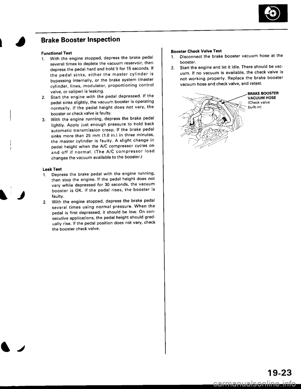
Booster Check Valve Test
1. Disconnect the brake booster vacuum hose at the
booster.
2. Stan the engine and let it idle. There should be vac-
uum. lf no vacuum is available, the check valve is
not working properly. Replace the brake booster
vacuum hose and check valve, and retest.
BRAKE BOOSTERVACUUM HOSE(Check valve
built-in)
Page 1179 of 2189
I
7.
11.
Clean the caliper thoroughly; remove any rust, and
check for grooves and cracks.
Check the brake disc for damage and cracks.
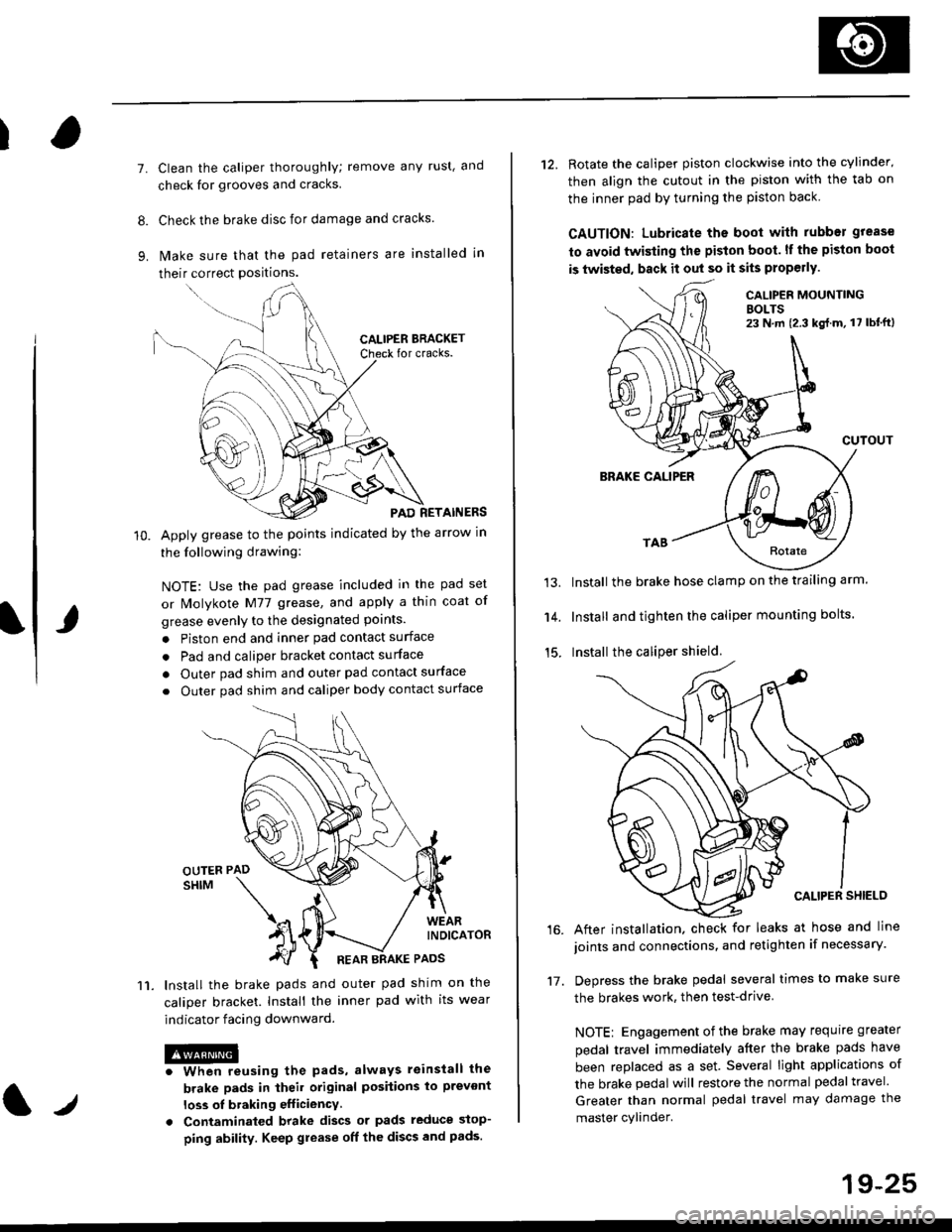
lvlake sure that the pad retainers are installed in
their correct positions.
PAD RETAINERS
Apply grease to the points indicated by the arrow in
the following drawing:
NOTE: Use the pad grease included in the pad set
or lMolykote M77 grease, and apply a thin coat of
grease evenly to the designated points.
. Piston end and inner pad contact surface
. Pad and caliper bracket contact surface
. Outer pad shim and outer pad contact surface
. Outer pad shim and caliper body contact surface
lnstall the brake pads and outer pad shim on the
caliper bracket. Install the inner pad with its wear
indicator facing downward.
@iwhen reusing the pads, always reinstall the
brake pads in iheil original posiiions lo prevont
loss ol braking efficiency
. Contaminaled brake discs or pads reduce stop-
ping ability. Keep grease off the discs and pads.
t./
19-25
12. Rotate the caliper piston clockwise into the cylinder'
then align the cutout in the piston with the tab on
the inner pad by turning the piston back
CAUTION: Lubricate ths boot with rubber grease
to avoid twisting the piston boot. lf the piston boot
is twisted, back it out so it sits properly.
CALIP€R MOUNTINGBOLTS23 N,m {2.3 kg{.m, 17 lbt'ft)
13.
14.
15.
CUTOUT
BRAKE CALIPER
Install the brake hose clamp on the trailing arm.
Install and tighten the caliper mounting bolts.
Install the caliper shield.
After installation. check for leaks at hose and line
joints and connections, and retighten if necessary.
Depress the brake pedal several times to make sure
the brakes work, then test-drive
NOTE: Engagement of the brake may requrre greater
pedal travel immediately after the brake pads have
been replaced as a set. Several light applications of
the brake pedal will restore the normal pedal travel.
Greater than normal pedal travel may damage the
master cylinder.
16.
17.
Page 1182 of 2189
Rear Brake Galiper
Disassembly (cont'd)
7. Remove the piston by rotating the piston counter-clockwise with the tool, and remove the piston
boot.
CAUTION: Avoid damaging the piston.
PISTON BOOTReplace.
Remove the piston seal.
CAUTION: Take care not to damage the cylinderbore.
CALIPER BODYCheck for scoring on
9. Install the special tool between the caliper bodv andspnng cover.
CAUTION: Be caretul not to damags the inside ofthe caliper cylinder during caliper disassembty.
BRAKE SPRINGCOMPRESSOR07HAE - SG00100
11.
LOCKNUTS
Position the locknuts as shown. then turn the shaftuntil the plate just contacts the caliper body.
NOTE: Do not compress the spring under thespring cover.
Turn the shaft clockwise 1/4 -'ll2 tu.n to comoressadjusting spring B in the caliper body.
CAUTION: To preyant damage to the inner compo-nonts. do not turn the shaft mor€ than 1/2 turn.
SHAFT
LOCKNUTS
PISTON SEALReplace.
ADJUSTII{GSPRING 8
19-28
Page 1189 of 2189
Rear Drum Brake
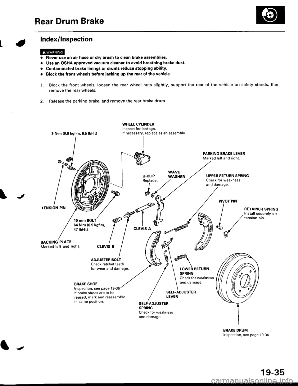
Index/lnspection
'1.
a
a
Never use an air hose or dly brush to clean brake assemblies,
Use an OSHA approved vacuum cleanar to avoid breathing brake dust,
Contaminated brake linings or drums reduce stopping ability.
Block the tront wheels before iacking up ths r€ar of lhe vehicle.
Block the front wheels, loosen the rear wheel nuts slightly, support the rear of the vehicle on safety stands, then
remove the rear wheels.
2. Release the parking brake, and remove the rear brake drum.
I N m 10.9 kgtm, 6.5 lbf.ftl
TENSION PIN
10 mm BOLT6,1N m 15.5 kgf m,47 tbf.ft)
WHEEL CYLINDERInspect for leakage.lf necessary, replace as an assembly.
u-cLrPReplace.
WAVEWASHER
PARKING BRAKE LEVERMarked left and right.
Check for weaknessano oamage,
UPPER RETURN SPRING
I
@JPIVOT PIN
BACKING PLATEMarked lelt and right-
/
€f-l.^
I I
*'t")
ctEv'sB
/ (t
/ ,.ro,".r r.*,"n
/ , Install securely on
| / tension pin.
d"/
IU
ADJUSTER BOI-TCheck ratchet teethfor wear and damage.LOWER RETURNSPRINGCheck for weaknessand oamage.BRAKE SHOEInspection, see page 19-36lf brake shoes are to bereused, mark and reassemblein same position.
SELF.ADJUSTERLEVEB
SELF-ADJUSTERSPRINGCheck for weaknessano oamage.
BRAKE DRUMInspection, see page '19 36
t
19-35
Page 1190 of 2189
Rear Drum Brake
Inspection
1.
4.
Check the wheel cylinder for leakage.
Check the brake linings for cracking, glazing, wear,
and contamination.
Measure the brake lining thickness.
Brake Lining Thickness:
Standard: 4.0 mm {0.157 in}
Service Limit: 2.0 mm 10.08 in)
NOTE; Measurement does not include brake shoe
thickness.
lf the brake lining thickness is less than the service
limit, replace the brake shoes as a set.
Check the bearings in the hub unit for smooth oper-
ation. lf defective, refer to section 18
WHEEL CYLINDER
LININGS
19-36
6. Measure the inside diameter oJ the brake drum
using the inside vernier calipers.
Drum Inside Diameter:
Standard: 199.9 - 200.0 mm {7.870 - 7.874 in)
Servic€ Limit: 201.0 mm (7.913 inl
lf the inside diameter of the brake drum is more
than the service limit, replace the brake drum.
Check the brake drum for scoring, grooves, and
cracks.
7.
8.
INSIDE VERNIER CALIPERS
BRAKE ORUM
Page 1191 of 2189
t-
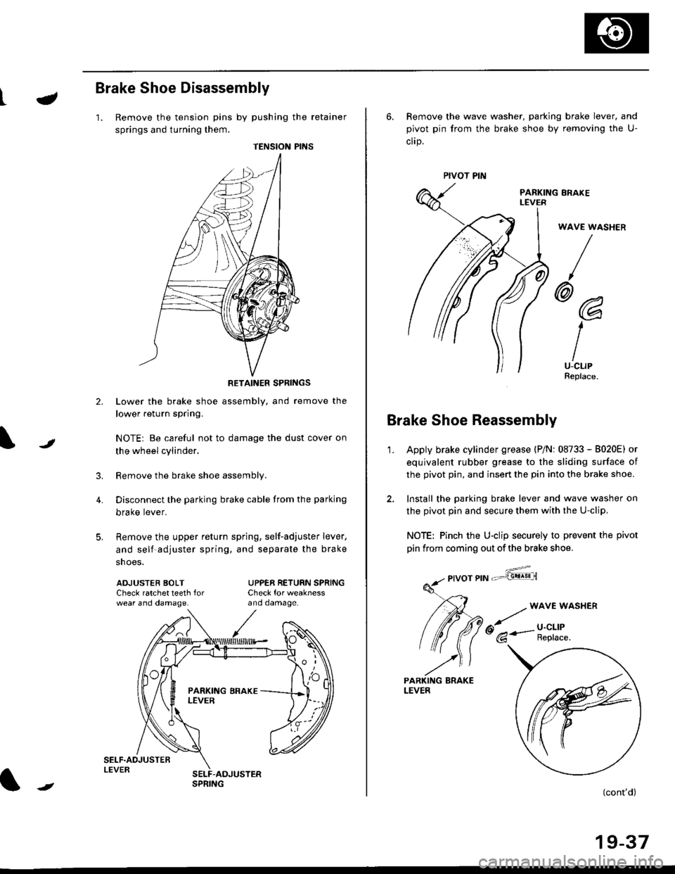
Brake Shoe Disassembly
1. Remove the tension pins by pushing the retainer
springs and turning them.
TENSION PINS
RETAINER SPRINGS
Lower the brake shoe assembly, and remove the
lower return spring.
NOTEi Be careful not to damage the dust cover on
the wheel cylinder.
Remove the brake shoe assembly.
Disconnect the parking brake cable from the parking
brake lever.
Remove the upper return spring, self-adjuster lever,
and self-adjuster spring, and separate the brake
snoe5.
t
3.
4.
ADJUSTEB BOLTCheck ratchet teeth forwear ano oamage.
UPPER RETURN SPRINGCheck for weaknessano oamage.
ll
,'/
N
r
//
t
6. Remove the wave washer, parking brake lever, and
pivot pin from the brake shoe by removing the U-
clrp.
PARKING ERAKEI-EVER
WAVE WASHER
/
@@
I
IU-CLIPReplace.
Brake Shoe Reassembly
1.Apply brake cylinder grease (P/Nr 08733 - B020E) or
equivalent rubber grease to the sliding surface of
the pivot pin, and insert the pin into the brake shoe.
Install the parking brake lever and wave washer on
the pivot pin and secure them with the U-clip,
NOTE: Pinch the U-clip securely to prevent the pivot
pin from coming out of the brake shoe.
,6;::"'
(cont'd)
19-37
LEVER
Page 1192 of 2189
Rear Drum Brake
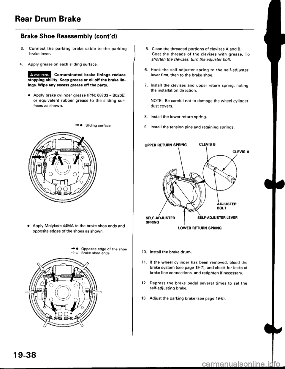
Brake Shoe Reassembly {cont'dl
Connect the parking brake cable to the parking
brake lever.
Apply grease on each sliding surface.
!@ contaminated brake linings reduce
stopping ability. Keep grease or oil off the blake lin-
ings. Wipe any excess grease off the parts,
. Apply brake cylinder grease {P/N: 08733 - 8020E)
or equivalent rubber grease to the sliding sur-
faces as shown.
+a Sliding surlace
Apply Molykote 44MA to the brake shoe ends and
opposite edges ofthe shoes as shown.
_' o Opposite edge of the shoe+O Brake shoe ends
19-38
13.
5. Clean the threaded portions of clevises A and B.
Coat the threads of the clevises with grease. To
shoften the clevises, tun the adjuster bolt.
6. Hook the self-adjuster spring to the self-adjuster
lever first, then to the brake shoe
7. Install the clevises and upper return spring. noting
the installation direction.
NOTE: Be careful not to damage the wheel cylinder
dust covers,
8. Install the lower return spring.
9. Install the tension pins and retaining springs.
uppER RETURT{ SpRtNG CLEVIS B
CLEVIS A
Installthe brake drum.
lf the wheel cylinder has been removed, bleed the
brake system (see page 19-7), and check for leaks at
brake line connections, and retighten if necessary.
Depress the brake pedal several times to set the
self-adjusting brake.
Adjust the parking brake (see page 19-6).
't0.
11.
12.
LOWER RETURN SPRING