Page 751 of 2189
Check the G.ound Circuit:Check for continuity between theA9 and A10 terminals.
. Rapair opan in the wirobotweon th6 tormin.b Ag rndA10 and G101.. Raprir looc€ iunction connrc{or.. R.p.ir poor ground {G101}.
Chock tor 100!6 PCM connectors.ll nocessary, substituto a known-good PCM and r6ch6ck.
Ftom page 14-72
PCM CONNECTOR A I32P}
Wiro side of t6male terminals
14-73
Page 754 of 2189

Electrical Troubleshooting ('96 - 98 Models)
Troubleshooting Flowchart - E Indicator Light Does Not Gome On
PCM CONNECTOR A I32PI
Wire side of female terminals
Tha E indicator light does nolcome on when the ignition swhchis first turned ON (lll. {lt shouldcome on tol about two s€conds.l
Chock the SeJvico Check Connec-tor:Make sure the special tool (SCS
Seryice Conneclor) is not connect-ed to the service check connector.
ls the special tool (SCS ServiceConnector) connected to the service check connector?
Disconnect the special tool tromthc sarvice check connoctor androcheck.
Check th6 E indicator Light:Shift to lD.l oosition.
Check tor loose PCM connecto6.ll nece3sary, sub.titute a known-good FCM and r.chock.
Check the Ground Circuit:'1. Turn the ignition switch OFF.2. Disconnecr the A {32P}connec-tor lrom the PCM.3. Check for continuity betweenthe A9 terminal and bodyground and the A22 terminaland body ground.
Repair op6n in tho wirgsbetween tho A9 ot M2 tormi-nals and G101.Rcpair poor glound {G101).
To page 14-77
l.
14-76
Page 756 of 2189
Electrical Troubleshooting ('96 - 98 Models)
Th6 E indicstor light is on con-st.ntly {not blinkingl wheneveithe ignition switch is ON lll).
Measure 04 IND Voltage:1. Turn the ignition switch OFF.2. Disconnect the B 125P) connec-tor from the PCM.3. Turn the ignition switch ON (ll).
4. Measure the voltage betweenthe 813 terminal and bodyground,
Repair 3hort to pow€. in the wirobetween the 813 terminal endthc gauge asiombly.
Meaiure ATP Dil Voltage:1. Turn the ignition switch OFF.2. Connect the I (25P) connectorto the PCM.3. Turn the ignition switch ON (ll).4. Shiftto any position otherthan
5. Measure the voltage betweenthe 824 terminal and bodygrou nd.
Check for a short to ground on thowir6. It wire i3 OK, .eplac6 the A/Tgoar po3ition indbator,
Troubleshooting Flowchart - E Indicator Light On Constantly
a!
PCM CONNECTOR B (25P)
Wire side of lemale terminals
l.
14-7A
Page 759 of 2189

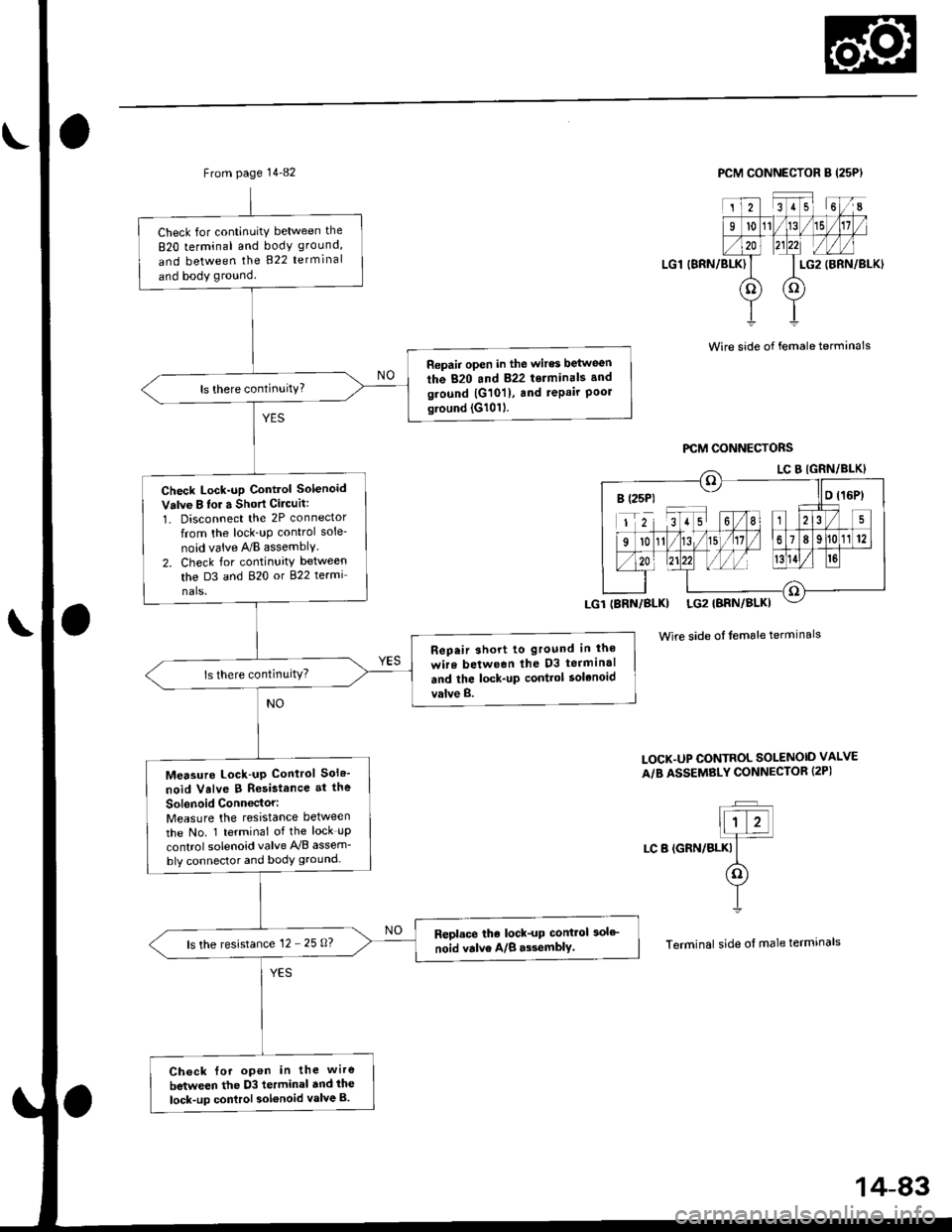
From page 14-80
Check lor continuity between the
820 terminal and body ground,
and between the B22 terminal
and body ground.
Ropair opon in thc wircs betwe6n
the 820 lnd 822 tolminals .ndground {G10ll, and tepair Poolground (G10'l).
Check Lock-up Cont.ol Solonoidvalve A for a Shon Cilcuit:1. Disconnect the 2P connectortrom the lock-up control sole-
noid valve ry'B assembly.
2. Check for continuity betlv€en
th6 D1 and 820 or 822 termi-
nals.
R6p.ir 3hort to glound in thc
wir. b.two.n the Dl torn|in.l
ard th. lock-up conttol iol.noid
valva A.
Maasuro Lock-up Control Sol.-
noid Vllve A Ro.istance at tho
Solanoid Conn6ctor:Measure the resistance between
the No. 2 terminal of the lock-up
control solenoid valve y'y'B assem-
bly connector and body ground.
R6placo tho lock-up control solo_
noid valve A/B.$6mblY.ls the resistance '12 - 25 O?
Chack for opon in tho wiro
botweon the Dl t..minal and tho
lock-up control solenoid Yalva A.
PCM CONNECTOR B {25P}
I.G1 (BRN/BLKI
Wire side of l6male terminals
PCM OONI{ECTORS
Wire side ot female terminals
LOCK.UP CO TROL SOTINOID VALVEA/B ASSEMBLY CON]TECTOR I2P}
]F]ALr-f-
I LC A {YEu
(o�)Y
I
Terminal side of male terminals
B (25p) ll o l16P)
IBRN/BLK} LG2IBRN/BLK}
14-A1
Page 761 of 2189

From page 14-82
Check for continuitY between the
820 terminal and body ground,
and between the 822 terminal
and body ground
Repair open in the wires between
the 820 and 822 terminals and
ground |G101), and repair Poolground (G1011.
Check Lock-up Control Solenoid
Valve B lor a Short Cilcuit:
1. Disconnect the 2P connector
from the lock_uP control sole-
noid vaive A/B assemblY.
2. Check for continuity between
the D3 and 820 or 822 termi
nals.
Rep.ir short to ground in lho
wire between lhe D3 terminal
and the lock-up contlol solenoid
valve B.
Measure Lock-up Control Sol6'
noid Valve B Resistance at the
Sol6noid Conn€ctor:Measure the resistance between
the No. 1 terminal of the lock uP
control solenoid valve A'lB assem_
bly connector and body ground-
Repl.ce the lock-up control 3olc
noid valve A/B a$emblY.ls the resistance 12 - 25 0?
Ch6ck {or open in the wire
between the D3 terminal dnd ihe
lock-up control sol€noid valve B.
PCM CONNECTOR B (25PI
LG1 (BRN/BLK)
2351 6I
l011/15
LG2
oo
(BRN/BLKI
Wire side of female terminals
Wire side of female terminals
LOCK.UP CONTROL SOLENOID VALVE
A/B ASSEMBLY CONNECTOR (2PI
t;T�Jllt z!]4
LC B (GRN/BLKI It(o)
YI
Terminal side of male termrnals
B (25P1 - llo t16Pt
14-83
Page 762 of 2189

Electrical Troubleshooting ('gg - 00 Models)
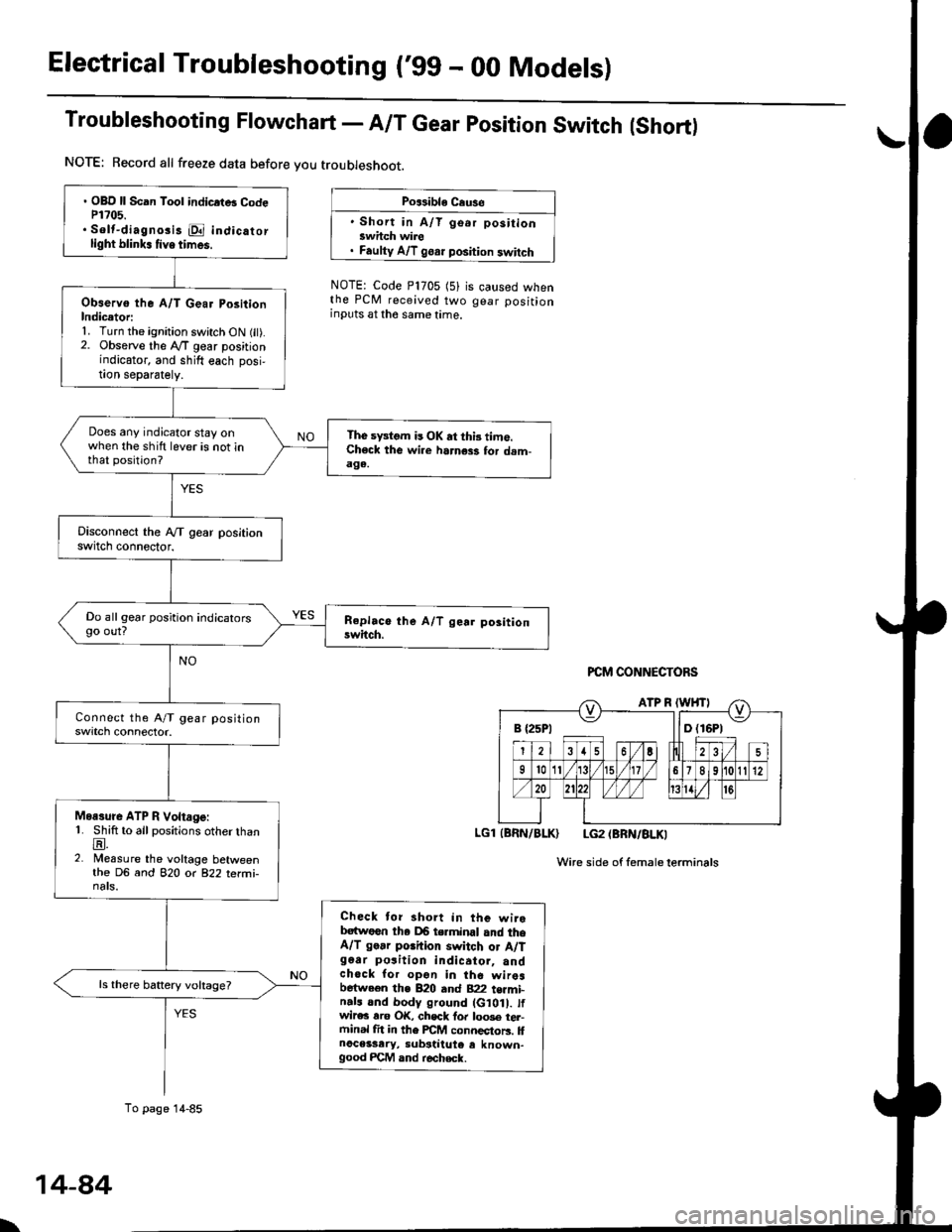
Troubleshooting Flowchart - A/T Gear position Switch (Short)
NOTE: Record all freeze data before you troubleshoot.
Po$ible Cause
' Short in A/T go.r positionswhch wire. Faulty A/T goar position switch
NOTE: Code P1705 (5)the PCM received twoinputs at the same time.
is caused whengear position
PCM CONNECTORS
LGl (BRN/BLK) LG2 (BRN/BLKI
Wire side of femaleterminals
B {25P1 llD (16P1
. OBD ll Scan Tool indicrtB CodeP1?05.. Solt-diagno3i3 E indicatorlight blink. tive times.
Observo the A/T Gear PositionIndicetori1. Turn the ignition switch ON fit).2. Observe the lVT gear positionindicator, and shift each posi,!on separately.
Does any indicator stay onwhen the shift lever is not inthat position?
The sFtom is OK at thi3 time.Check the wi.e harness for dam-aga.
Do all gear position indicatorsgo out?
Moasure ATP R Voltage:1. Shift to all positions otherthanE.2. Measure the voltage betweenthe DG and 82O o( 822 terfii-nats.
Check tor short in the wirebatwoen tha DB terminal and theA/T go.r porhion switch or A/Tg6ar po3ition indicator, andchock for opon in the wiresbetween the B20 and B22 t€rmi-n.ls and body ground (G10 . tfwir€c rro OK, chsck fo. loo3e tel-ftinal fit in the FCM connectors. llnoceisary, substiiute e known-good FCM and r€check.
ls there battery voltage?
To page 14-85
\
14-84
Page 768 of 2189

Electrical Troubleshooting ('gg - 00 Models)
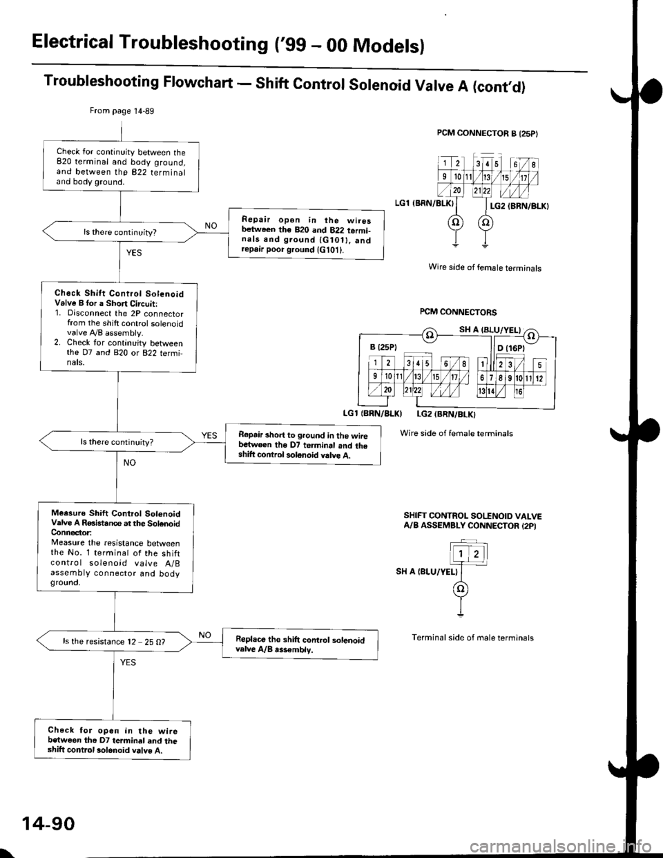
Troubleshooting Flowchart - Shift Control Solenoid Valve A (cont,O)
PCM CONNECTOR B {25P}
LGl (BRN/BLKI
Wire side of female terminals
rcM CONNECTORS
LGl {BBN/BLKI LG2 (BRN/BLKI
Wire side of female terminals
SHIFT CONTROL SO|'INOID VALVEA/B ASSEMBLY CONNECTOR I2PI
SH A {BLU/YELI
From page 14-89
Check lor continuity between the820 terminal and body ground,and between the 822 terminaland body ground.
Repair open in ihe wiresbetween th€ 820 and 822 termi-nals end ground {G10ll. andrepa,r poor ground {G101}.
Check Shitt Control SolenoidValve B for a Short Circuit:1. Disconnect the 2P connectorfrom the shilt control solenoidvalve A,/B assembly.2. Check lor continuity betweenthe D7 and 820 or 822 termi,nals.
R€pair short to ground in the wiiebartwe€n the D7 te.minal and theshift control solonoid valve A.
ls there continuity?
Meesuro Shift Control SolenoidValve A RGistance at the SolenoidConnector:Measure the resistance betweenthe No. 1 terminal of the shiftcontro I solenoid valve A/Bassembty connector and bodygrounct,
Repl.ce tho shift control solenoidvalve A/B rss€mblv.ls the resistance 12 25 O?
Check for open in the wirebetween the D7 termindl and theshift control 3olonoid valve A.
B t25Pt llD t16Pt
\
14-90
Page 770 of 2189

Electrical Troubleshoot:ng ('gg - 00 Models)
Troubleshooting Flowchart - Shift Control Solenoid Valve B (cont,dl
PCM CONNECTOR A {25PI
LGl (BRN/BLK)
IBRN/BLKI LG2IBRN/BLK)
Wire side of temale terminals
Wire sid€ ot female terminals
FCM CONNECTORS
SHIFT @NTROL SOENOID VALVEA/A ASSEMBLY CONNECTOR (2PI
.-_
1)2-.T-
I sn e tcanlwxrt
(o
YI
Terminal side oI male terminals
Check for continuity between the820 terminal and body ground,and between the 822 terminaland body ground.
Ropair opan in the wirgsb.twocn the 820 rnd 822 te.mi,n.ls and ground lG10t), and..p.ir poor ground lG10t).
Check Shift Control Sol.noidVrlve B tor a Short Ci.cuit:1. Disconnect the 2P connectorfrom the shift control solenoidvalve A/B assembly.2. Check for continuity betweenthe D2 and 820 or 822 termi-nals.
Repair 3hort to ground in tho wirebotw.en tha 02 torminsl and theshift com.ol rolonoid v.lv. B.
Meaiuro Shift Cont.ol SolonoidVrlve B Raailtrnca at the SolonoidConn€c,toa:Messure the r€sistance belweenthe No. 2 terminal of the 6hiftcontrol solenoid valve A/Bassembly connector and bodyground.
R.pl.co th. 3hift control lolenoidv!lv. A/8.lsombly.ls the resistance 12 - 25 O?
Chack for open in the wi.ebetwoon th€ D2 termin.l and the3hift control lolanoid valv6 8.
B (25P1 - llDt
From page'14-91
SH B (GRN/WHTI
\
14-92