Page 817 of 2189

Valve Body
2.
Repair
NOTE: This repair is only necessary if one or more of
the valves in a valve body do not slide smoothly in their
bores. You may use this procedure to free the valves in
the valve bodies.
1. Soak a sheet of #600 abrasive paper in ATF for
about 30 minutes.
Carefully tap the valve body so the sticking valve
drops out of its bore.
CAUTION: lt may b€ necessary to use a small
screwdriver to pry the valve free. Be careful not to
scratch the bore whh the screwdriver.
Inspect the valve for any scuff marks. Use the ATF-
soaked #600 paper to polish off any burrs that are
on the valve, then wash the valve in solvent and dry
it with compressed a ir.
Roll up half a sheet of ATF-soaked paper, and insert
it in the valve bore of the sticking valve.
Twist the paper slightly, so that it unrolls and fits the
bore tightly, then polish the bore by twisting the
paper as you push it in and out.
CAUTION: The valve body is aluminum and doesn't
require much polishing to remove any burrs,
3.
4.
ATF-soaked#600 abrasive Paper
5.
7.
Remove the #600 paper and thoroughly wash the
entire valve body in solvent. then dry it with com-
pressed air.
Coat the valve with ATF, then drop ir into its bore.
It should drop to the bonom of the bore under its
own weight. lf not, repeat step 4, then retest.
VALVE BODY
Remove the valve. then thoroughly clean it and the
valve body with solvent. Dry all parts with com-
pressed air. then reassemble using ATF as a lubri
cant.
W
-M
14-139
Page 882 of 2189
Description
Electronic Control System ('gG - 98 Modelsl (cont'dl
Circuit Diagram and Terminal Locations
GNITIONSWITCN
Pri - Pt coNTnoLLrN ns0LtN0t0
SIAiT CLUTCH CONTSOLLINEAFSOLENOID
sHtFT CONmOILINIAftSOLENOID
BFAXELIGHT
PAS|(ING 8MI(E SWITCH
i\c-...............- +B
i\--------.--_ rcr
: MAP(PBIg s61
E rtDiRxo
g TM8
scs
123518I1011't22578910
14172023261213t4t6171820
D
14-204
Page 900 of 2189
Description
Park Mechanism
The park mechanism locks the transmission by engaging the park pawl with the park gear which is integral with the sec-ondary drive gear' The secondary drive gear engages with the secondary driven gear which engages wit-h the final drivengear.
shifting to E position causes the park cone (installed at the end of the park rod) to press the park pawl onto the park gear.Even if the end of the park pawl rides on the top of the park gear teeth, slight movement of the vehicle will cause the parkpawl and the park gear to mesh with each other completely because the park cone receives the tension from the park rodspring The park pawl receives the tension (which acts to separate the park pawl from the park gear) from the park pawlspring.
PARK PAWI-
PARK CONE
START CLUTCH
PABK GEAR
PARK RODPARK PAWL
PARK ROOSPRING
14-222
D
Page 905 of 2189

TCM Terminal Voltage/Measuring Gonditions
('96 - 98 Modelsl
TCM Terminal Loc.tions
TCM-A l25P) Connecto.
TCM CONNECTOR A (26P}
TCM-B (22P) Connectot
2418910111213
1115161720232526
Terminal NumbetSignalDsscriptionMoasuring Conditions/Torminsl Vohrgo
A1SC LS_Stan clutch control linear solenoidpower supply negative electrodeEngine idling, E position:Approx. 0.4 VHLC LS-PH-PL control linear solenoid Dowersupply negative electrodeEngine idling, E position:Approx. 0.7 V
Shift control linear solenoid oowersupply negative electrodeEngine idling, E position:Approx. 0.8 V
A4LG1Ground
NEEngine speed signal inputWith engine running: Pulsing signalA6Not used
A7ATP LA/f gear position switch El positionsignal inputInEposition:OVIn other than El position: Approx. 1O VA8ATP Sly'T gear position switch E positionsignal inputIn lg position: 0 VIn other than E position: Approx. 10 VA9ATP DA{/T gear position switch E positionsignal inputIn lll position: 0 VIn other than E position: Approx. 10 VAr0ATP NPA,/T gear position switch E or Eposition signals inputInEorEposition:oVIn otherthan E orE position: Approx. 1O VA11ATP RA,/T gear position switch E positionsignal inputIn lE position: 0 VIn other than E position: Approx. 1O VA.12tGlPower supply systemWith ignition switch ON (ll): Banery voltsgeWith ignition switch OFF: 0 VA13PG1Ground
414Start clutch control linea. solenoidpower supply positive electrodeEngine idling, E position:Approx. 2.5 VA15HLC LS+PH-PL control line8|. solenoid powersupply positive electrodeEngine idling, El position:Approx. 5.0 VA16SH LS+Shift control linear solonoid oowersupply positive electrodeEngine idling, E position:Approx. 6.0 V417Ground
A18Not used
A19Not used
420D INDE indicator light controlWhen l9l indicator light comes on: Approx. jO VWhen lll indicator lighr OFF: 0 VA2'lNot used
422Not used
VBUBack-up power systemAlways battery voltage424Not used
A.25tG1Power supply systemWith ignition switch ON (lt): Baftery voltageWith ignition switch OFF:0 VPG1Ground
L
14-228
Page 910 of 2189
![HONDA CIVIC 2000 6.G Workshop Manual \a
PCM CONNECTOR D {16P)
14-233
Terminal Numbs]SignalDescriptionMeasuring Conditions/Terminal Voltage
D1VELSecondary gear shaft speed
sensor signal input
Depending on vehicle speed: Pulsing signal
Whe HONDA CIVIC 2000 6.G Workshop Manual \a
PCM CONNECTOR D {16P)
14-233
Terminal Numbs]SignalDescriptionMeasuring Conditions/Terminal Voltage
D1VELSecondary gear shaft speed
sensor signal input
Depending on vehicle speed: Pulsing signal
Whe](/manual-img/13/6068/w960_6068-909.png)
\a
PCM CONNECTOR D {16P)
14-233
Terminal Numbs]SignalDescriptionMeasuring Conditions/Terminal Voltage
D1VELSecondary gear shaft speed
sensor signal input
Depending on vehicle speed: Pulsing signal
When vehicle is stoPPed: APProx. 0 V
02SOL INHlnhibitor solenoid controlWith inhibitor solenoid ON: Battery voltage
With inhibitor solenoid OFF: 0 V
D3SH LSMShift control linear solenoid
power supply negative electrode
D4SH LSPShift control linear solenoid
power supply positive electrode
With ignition switch ON (ll): Pulsing signal
D5VB SOLPower supply for solenoid valvesWith ignition switch ON (ll): Baftery voltage
With ignition switch OFF:0 V
D6ATP RA,/T gear position switch E
position input
InEposition:0V
In other than B position; Approx. 10 V
D]VEL SGSecondary gear shaft sPeed
sensor ground
D8Not used
D9Not used
D10NDNDriven pulley speed sensor signal
anput
In other than E and E position: Pulsing signal
D11NDRDriven pulley speed sensor signal
input
ln other than E and E position: Pulsing signal
D12NDR SGDrive pulley speed sensor ground
D13ATP SA,/T gear position switch E
position input
InE position: 0V
In other than E position: Battery voltage
D14D INDD indicator light controlWhen ignition switch is first turned ON (ll):
Battery voltage for two seconds
In E position: Battery voltage
D15Not used
D16NDN SGDriven pulley speed sensor
grou nd
Page 911 of 2189

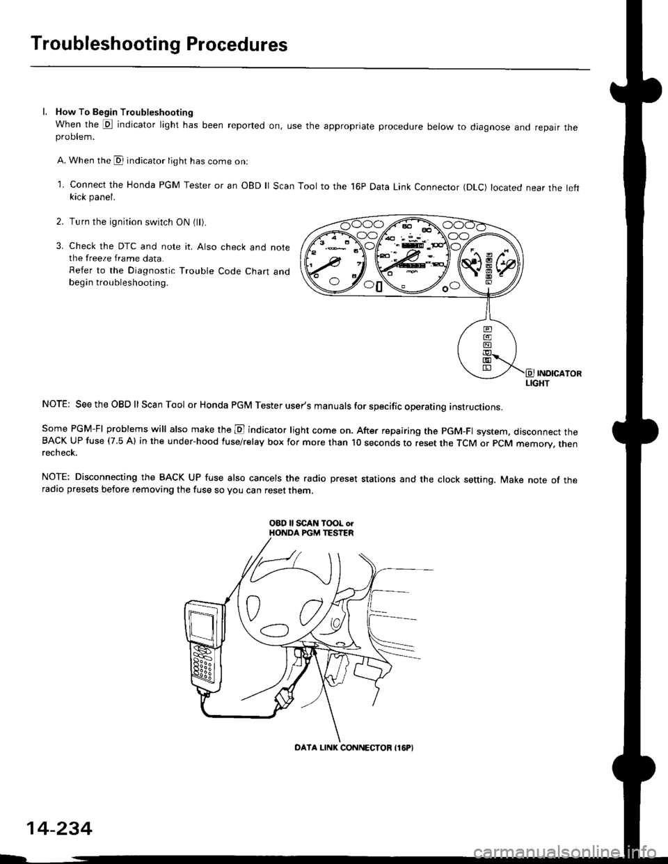
Troubleshooting Procedures
l. How To Begin Troubleshooting
When the E indicator light has been reported on, use the appropriate procedure below to diagnose and repatr theproDlem.
A. When the @ indicator light has come on:
l connect the Honda PGM Tester or an oBD ll Scan Tool to the 16P Data Link Connector (DLc) located near the leftkick panel.
Turn the ignition switch ON (ll).
Check the DTC and note it. Also check and notethe freeze frame data.
Refer to the Diagnostic Trouble Code Chart andbegin troubleshooting.
INOICATORLIGHT
NOTE: SeetheOBDll Scan Tool or Honda PGM Tester user's manuals for specific operating instructions.
Some PGM-FI problems will also make the E indicator light come on. After repairing the pGM-Fl system, disconnect theBACK UP fuse (7.5 Al in the under-hood fuse/relay box for more than l0 seconds to reset the TCM or PCM memory, rnenrecheck.
NOTE: Disconnecting the BACK UP fuse also cancels the radio preset stations and the clock setting. Make note of theradio presets before removing the fuse so you can reset them,
2.
3.
o0\e--loo
OATA LINK CONNECTOB I16P}
14-234
Page 912 of 2189

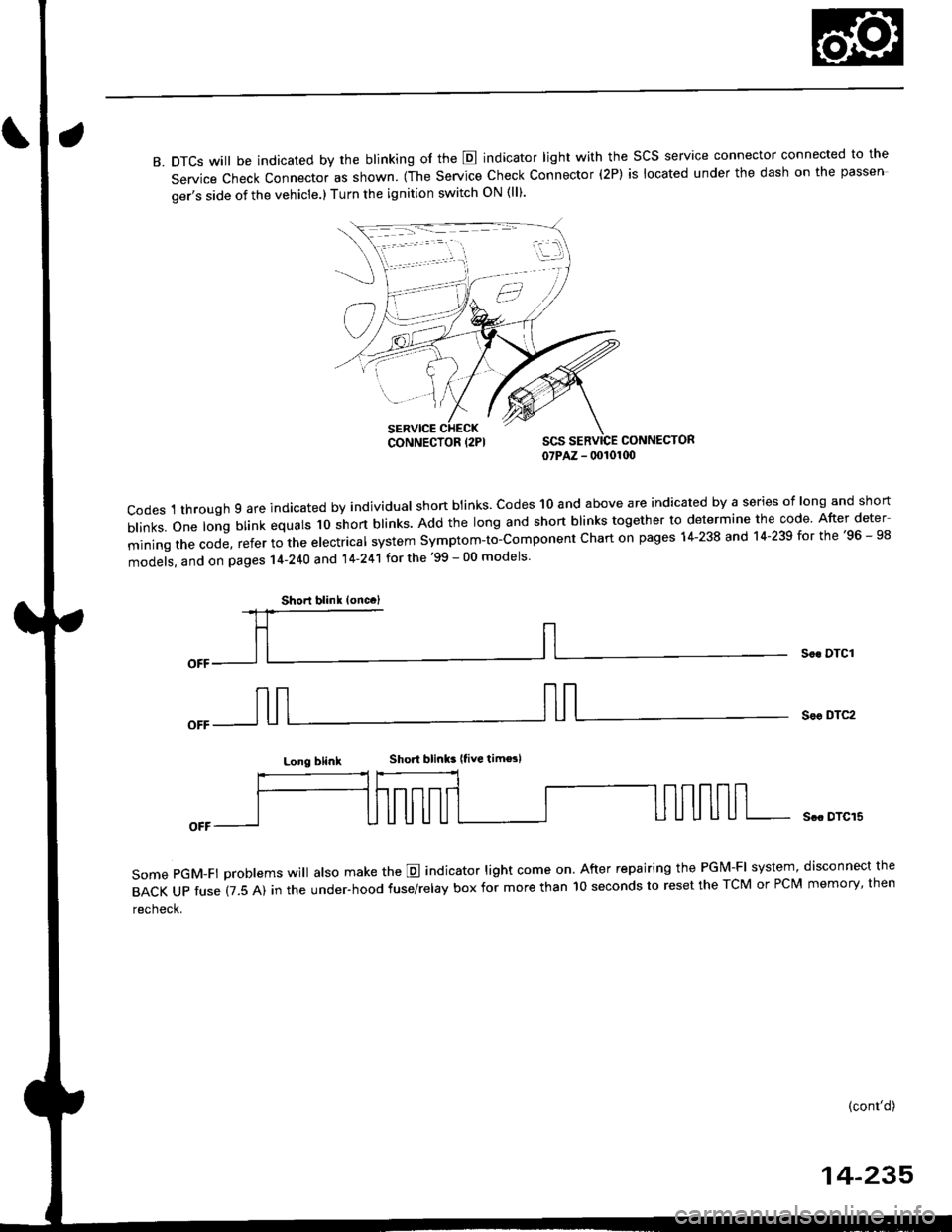
B. DTCS will be indicated by the blinking of the E indicator light with the SCS service connector connected to the
Service Check Connector as shown. (The Service Check Connector (2P) is located under the dash on the passen
ger's side of the vehicle.) Turn the ignition switch ON (ll).
CONNECTOR07PAZ - 00101(x)
codes 1 through 9 are indicated by individual shon btinks. codes 10 and above are indicated by a series of long and short
b|inks.one|ongblinkequa|sloshortb|inks.Addthe|ongandshortb|inkstogethertodeterminethecode.Afterdeter
miningthecode,refertothee|ectrica|systemsymptom-to-componentchartonpagesl4-238and14.239forthe,96_98
models, and on pages 14-240 and 14'241 for the '99 - 00 models
Soc DTCI
Sor DTC2
Long blinkShort blinks |tive tim€sl
some pGM-Ft problems wi
atso make the E indicator light come on. After repairing the PGM-FI system, disconnect the
BACKUPfuse(7.5A)intheUnder.hoodfuse/re|ayboxformorethanl0secondstoresettheTcMorPcMmemory,then
recheck.
Scc DTCI5
(cont'd)
14-235
iii:j
,,,/
CONNECTOR {2PI
Shorl blink (oncc)
Page 915 of 2189

Symptom-to-Component Chart
Electrical System -'96 - 98 Models
*: The DTC in parentheses is the code @ indicator light indicates when the Data Link Connector is connected to the HondaPGM Tester.
DTC*O Indicator
LightMILDetection ltemPage
P1790
(3)BlinksONThrottle position sensor14-242
P179'l
(4)BlinksONVehicle speed sensor14-243
P1705
(5)BlinksONAy'T gear position switch (short to groundl't 4-244
P1706
(6)OFFONA/T gear position switch {open)14-246
P0725
(11)BlinksONlgnition coil14-248
P1793
112lBlinksONManifold absolute pressure sensor14-249
P 1870(30)BlinksONShift control linear solenoid14-250
P'1873
(311BlinksONPH-PL control linear solenoid14-25'l
P1879(32)BlinksONStart clutch control linear sotenoid14-252
P1882BlinksONInhibitor solenoid14-253
P1885
(34)BlinksONDrive pulley speed sensor1l-Zb4
P1886(35)BlinksONDriven pulley speed sensor14-255
P1888
(36)BlinksONSecondary gear shaft speed sensor14-256
T to55
(37)BlinksONECM or TCM14-257
P1890
l42lBlinksONShift control system14-259
P1891
(43)BlinksONStart clutch control svstem14-260
14-23a