Page 1665 of 2189
Window Antenna Coil Test
2.
1.
wtNoowANTENNAcotL
Remove the rear shelf (see section 20).
Disconnect the 2P and lP connectors from the win-
dow antenna coil.
1P CONNECTOB
2P
-l
CONNECTOR
3.Check for continuity between terminal A1 and body
ground and between terminals 41 and 81.
lf there is no continuity at either check, replace the
window antenna coil.
lq 81 1l
tf--llLB2lllL-,--rl
23-195
Mast Antenna Replacement
1.
2.
Disconnect the connector between the antenna lead
and sub antenna lead.
Remove the two mounting screws, then remove the
mast antenna.
MAST ANTENNA
MOUNTING SCREWS
Page 1670 of 2189
Rear Window Defogger
Gomponent Location Index
36 - 98 modols:
UNDER.DASH FUSE/RELAY BOX
REAR WINDOW DEFOGGER SWITCHInput Test, page 23-203
REAR WINOOW DEFOGGERRELAYTest, page 23-86
REAR WINOOW OEFOGGERFunction Test, page 23'202Defogger Wire Repair. page 23 202
23-200
Page 1671 of 2189
'99 - 00 models:
UNDER.OASH FUSE/RELAY BOX
REAR WINDOW DEFOGGER(Built into climate control unit)
REAR WINDOW DEFOGGER
Test, page 23-86
ANTENNA COIL (Sedsn)
f l_ f= L'
''rofia trF.-lj
l-
REAR WINDOW DEFOGGER
I est, page lr- lv.t
23-201
Page 1672 of 2189
Rear Window Defogger
Circuit Diagram
36 - 98 models:IGNITIONswtTcH
/ BAT \+ ots't
\:7 |
I
IIYE
WHT/BLK +WHT
wtNDow
BLKBLU
It-lt-l
TBLK
UNOEF,HOOD FUSE/RELAY BOX
N0.41 (e,oA) No a2 (aoA)
G40lG402G601 : Coupe/SedanG77t :Nalchback
23-202
Page 1673 of 2189
'99 - 00 models
IGNITONSWTCH
-fO Ctsr
\j7 |
I
I
WHT/BLK +WHT
HEATERPUSHswtTcH
BLK
G40lG402
BLK
G401G402
UNDER HOOD FUSEi RELAY BOX
No 4r (80A) No 42 (40A)
8
CLIMATE CONTROLUNIT/ R€ar window delogg€t \I I mer orcLril blill nlo J\climale conlro unil /
I{/\A-4<-INDICATOS(LE0)
II
REAF WINDOWDEFOGGEBswtTcH7 16
,ll
23-203
l-
Page 1674 of 2189

Rear Window Defogger
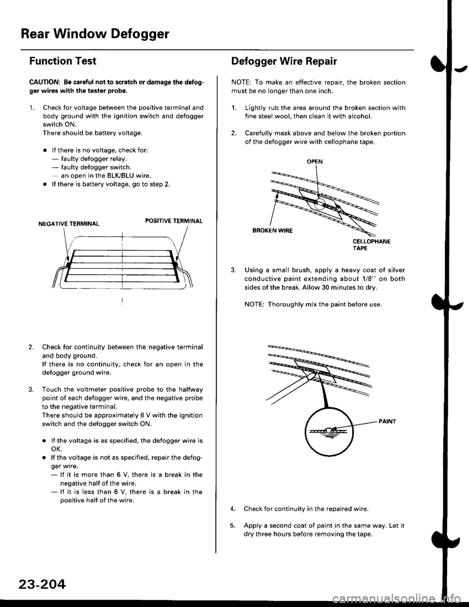
Function Test
CAUTION: Bs careful nol to scralch or damage the defog-
ger wires with the tester probe,
'1. Check for voltage between the positive terminal and
body ground with the ignition switch and defogger
switch ON.
There should be banery voltage.
. lf there is no voltage, check for:- faulty defogger relay.- faulty defogger switch.
an ooen in the BLK,/BLU wire.
. lf there is battery voltage, go to step 2.
POSITIVE TERMINAL
2. Check for continuity between the negative terminal
and body ground.
lf there is no continuity, check for an open in the
defogger ground wire.
Touch the voltmeter positive probe to the halfway
point of each defogger wire, and the negative probe
to the negative terminal.
There should be approximately 6 V with the ignition
switch and the defogger switch ON.
. lf the voltage is as specified. the defogger wire is
oK.
. lf thevoltage is not as specified, repairthe defog-
ger wrre.- lf it is more than 6 V, there is
negative half of the wire.- lf it is less than 6 V, there is
positive half of the wire.
a break in the
a break in the
23-204
OPEN
?
Defogger Wire Repair
NOTE: To make an effective repair, the broken section
must be no longer than one inch.
1, Lightly rub the area around the broken section with
fine steel wool, then clean it with alcohol.
2. Carefully mask above and below the broken portion
of the defogger wire with cellophane tape.
CELLOPHANETAPE
Using a small brush, apply a heavy coat of silver
conductive paint extending about 1/8" on both
sides of the break. Allow 30 minutes to dry.
NOTE: Thoroughly mix the paint before use.
Check for continuity in the repaired wire.
Apply a second coat of paint in the same way. Let it
dry three hours before removing the tape.
Page 1675 of 2189
Switch Input Test
CAUTION: Be careful not to damagc the rear window
defogger switch or the center panel when prying the
switch out.
NOTE: Before testing, check for blown No. 16 (7.5 A)
fuse in the under-dash fuse/relay box,
1. Pry the switch out of the center panel (see section 20).
2. Disconnect the 5P connector from the switch.
3. Turn the jgnition switch ON (ll), and check the voltage
between the BLVBLU {+) and the BLK (-)terminals.
There should be battery voltage
. lf there is no voltage, check for an open in the
BLVBLU wire.
. lfthere is baftery voltage, go to step 4.
Wire side of famale terminals
connect a jumper wire between the BLK/BLU and
the BLU/YEL terminals.
Turn the ignition switch ON (ll), and check that the
rear window defogger works; if it does. replace the
defogger switch.
4.
RED
l-
23-205
Page 1684 of 2189
Wipers/Washers
Component Location Index
SBS components are located in this area, Review the SRS component locations, precautions, and procedures in the SRSsection (241 betore performing repairs or service.
WIPER/WASHER SWITCHTest, page 23-215REAR WINDOW WIPERMOTOR lHatchback)Test, page 23'216WINDSHIELD WIPER ARMS/BLADES
WINDSHIELD WIPER MOTORTest, page 23-215
WASHER FLUIDRESERVOIR
WASHER MOTOR {Hatchback)Test, page 23'216
INTERMITTENT WIPER RELAYCIRCUIT (ln the integratedcontrol unit)
t_l
Iilr
i
T
23-214