2000 HONDA CIVIC turn signal
[x] Cancel search: turn signalPage 2036 of 2189
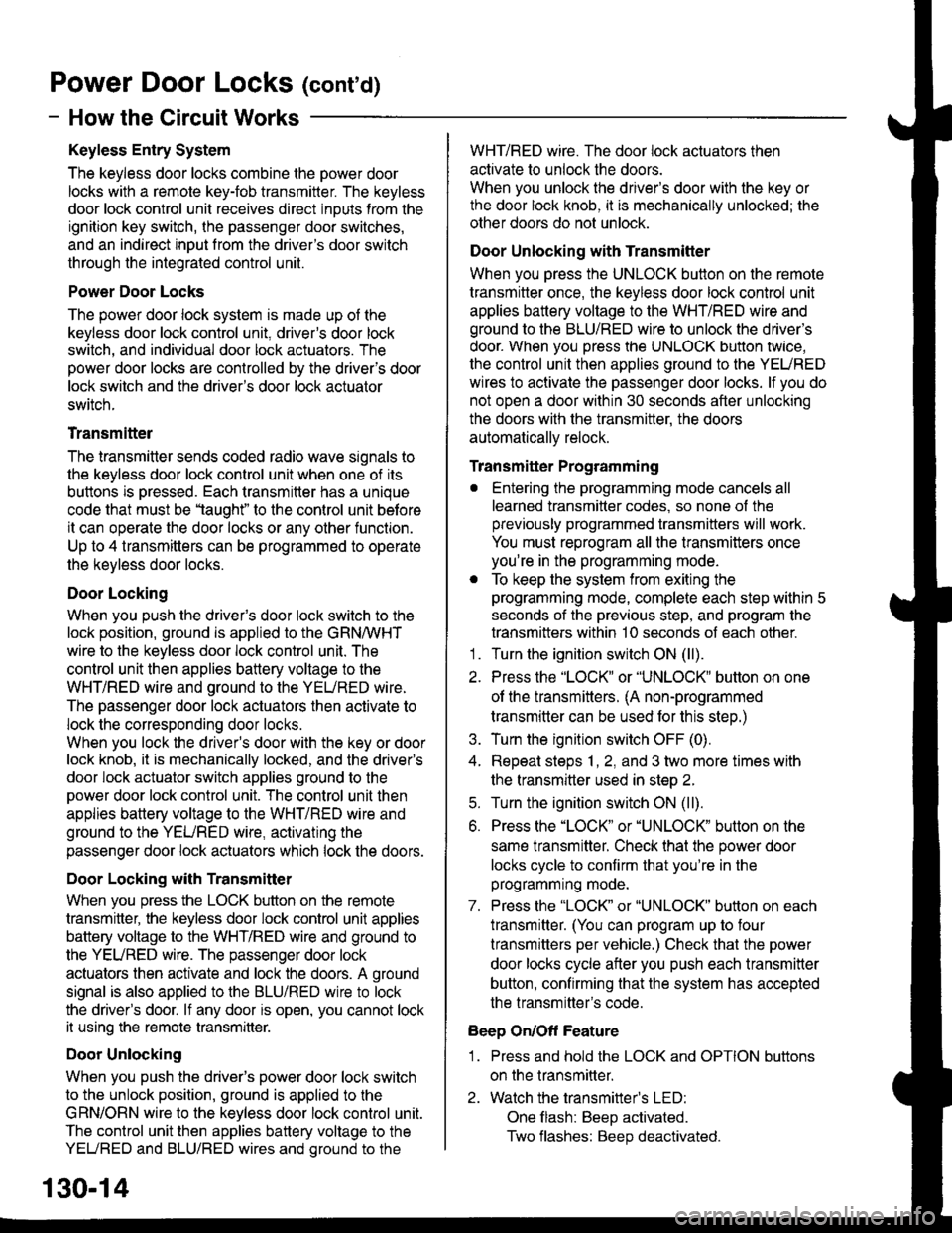
Power Door Locks (conrd)
- How the Circuit Works
Keyless Entry System
The keyless door locks combine the power door
locks with a remote key-fob transmitter. The keyless
door lock control unit receives direct inputs from the
ignition key switch, the passenger door switches,
and an indirect inDut from the driver's door switch
through the integrated control unit.
Power Door Locks
The power door lock system rs made up ot the
keyless door lock control unit, driver's door lock
switch, and individual door lock actuators. The
power door locks are controlled by the driver's door
lock switch and the driver's door lock actuator
switch.
Transmittel
The transmitter sends coded radio wave signals to
the keyless door lock conlrol unit when one of its
buttons is pressed. Each transmitter has a unique
code that must be 'laught" to the conlrol unit before
it can operate the door locks or any other function.
Up to 4 transmitters can be programmed to operate
the keyless door locks.
Door Locking
When you push the driveas door lock switch to the
lock position, ground is applied to the GRNMHT
wire to the keyless door lock control unit. The
control unit then applies battery voltage to the
WHT/RED wire and ground to the YEURED wire.
The passenger door lock actuators then activate to
lock the corresponding door locks.
When you lock the dnver's door with the key or door
lock knob, it is mechanically locked, and the driver's
door lock actuator switch applies ground to the
oower door lock control unit. The control unit then
applies battery voltage to the WHT/RED wire and
ground to the YEURED wire, activating the
passenger door lock actuators which lock the doors.
Door Locking with Transmitter
When you press the LOCK button on the remote
transmitter, the keyless door lock control unil applies
battery voltage to the WHT/RED wire and ground to
the YEURED wire. The passenger door lock
actuators then activate and lock the doors. A ground
signal is also applied to the BLU/RED wire to lock
the driver's door. lf any door is open, you cannot lock
it using the remote transmitter.
Door Unlocking
When you push the driver's power door lock switch
to the unlock position, ground is applied to the
GRN/ORN wire to the keyless door lock control unil.
The control unit then applies battery voltage to the
YEUREO and BLU/RED wires and oround to the
WHT/RED wire. The door lock actuators then
activate to unlock the doors.
When you unlock the driver's door with the key or
the door lock knob, it is mechanically unlocked; the
other doors do not unlock.
Door Unlocking with Transmitter
When you press the UNLOCK button on the remote
transmitter once, the keyless door lock control unit
applies battery voltage to the WHT/RED wire and
ground to the BLU/RED wire to unlock the driver's
door. When you press the UNLOCK button twice,
the control unit then applies ground to the YEURED
wires lo activate the passenger door locks. lf you do
not open a door within 30 seconds after unlocking
the doors with the transmitter, the doors
automatically relock.
Transmitter Programming
. Entering the programming mode cancels all
learned transmitter codes, so none of the
previously programmed transmitters will work.
You must reprogram all the transmitters once
you're in the programming mode.
. To keep the system from exiting the
programming mode, complete each step within 5
seconds of the previous step, and program the
transmitters within 10 seconds of each other.'1 . Turn the ignition switch ON (ll).
2. Press the "LOCK" or "UNLOCK" button on one
of the transmitters. (A non-programmed
transmitter can be used for this step.)
3. Turn the ignition switch OFF (0).
4. Repeat steps 1, 2, and 3 two more times with
the transmitter used in step 2.
5. Turn the ignition switch ON (ll).
6. Press the "LOCK" or "UNLOCK" button on the
same transmitter. Check that the power door
locks cycle to confirm that you're in the
programmrng mooe.
7. Press the "LOCK" or "UNLOCK" button on each
lransmitter. (You can program up to four
lransmitters per vehicle.) Check that the power
door locks cycle after you push each transmitter
button, contirming that the system has accepted
the transmitter's code.
Beep On/Off Feature
1 . Press and hold the LOCK and OPTION buttons
on the transmitter.
2. Watch the transmitter's LED:
One flash: BeeD activated.
Two flashes: Beep deactivated.
130-14
Page 2109 of 2189
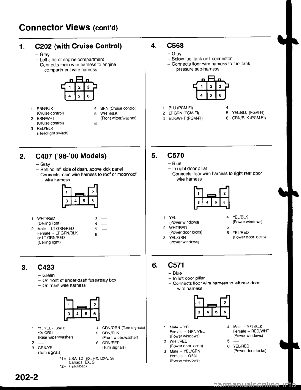
Connector Views (cont'd)
1. C202 (with Cruise Control)
- Gray- Left side ol engine compartment- Connects main wire harness to engine
compartment wre harness
gRN/BLK
(Cruise control)
BRN,ryVHT(Cruise control)
RED/BLK(Headlight switch)
BRN {Cruise conkol)
WHT/BLK(Front wipetwashel)5
4.c568
- Gray- Below Juel tank unit connector- Connects floor wire harness to tuel tank
pressure suo-narness
BLU (PGi.4-Fr)
LT GRN (PGM-FI)
BLl(WHT (PGI\4-FD
YEUBLU (PGM,FI)
GRN/BLK (PGI\,4.FD
4
5
2. C407 ('98-'00 Models)
- Gray- Behind left side ol dash, above kick panel
- Connects main wire harness to roof or moonroo{
wtre harness
WHT/RED(Ceiling light)
l\4ale - LT GRN/REDFemale - LT GRN/BLKor LT GRN/RED(Ceiling light)
5
5.c570
- Blue- In right door pillar- Connects floor wire harness to right rear door
wlre hafness
2
3
YEL(Power windows)
WHT/RED(Power door locks)
YEUGRN(Power wrndows)
YEL/BLK(Power windows)
YEURED(Power door locks)
5
6
3.c423
- Green- On Jront of under-dash tuse/relay box- On main wire harness
*1: YEL (Fuse 3)*2: GRN(Rear wiper/washe4
GRN/YEL(Turn signals)
GRN/ORN {Tu.n signals)
GRN/BLK(Front wiper/washer)
GRN/RED(Turn signals)
5
62
3
*1= USA: tX, EX, HX, DX-V SiCanada: EX, Si*2= Hatchback
202-2
6.c571
- Blue- In lett door pillar- Connects floor wire harness to lett rear door
wlre harness
MaIe _ YELFemale - GBN/YEL(Power windows)
WHT/RED(Power door locks)
Male - YEUGRNFemale - GBN(Power windows)
5
6
N4ale YEUBLKFemale - RED,ryVHT(Power windows)
YEURED(Power door locks)
Page 2110 of 2189
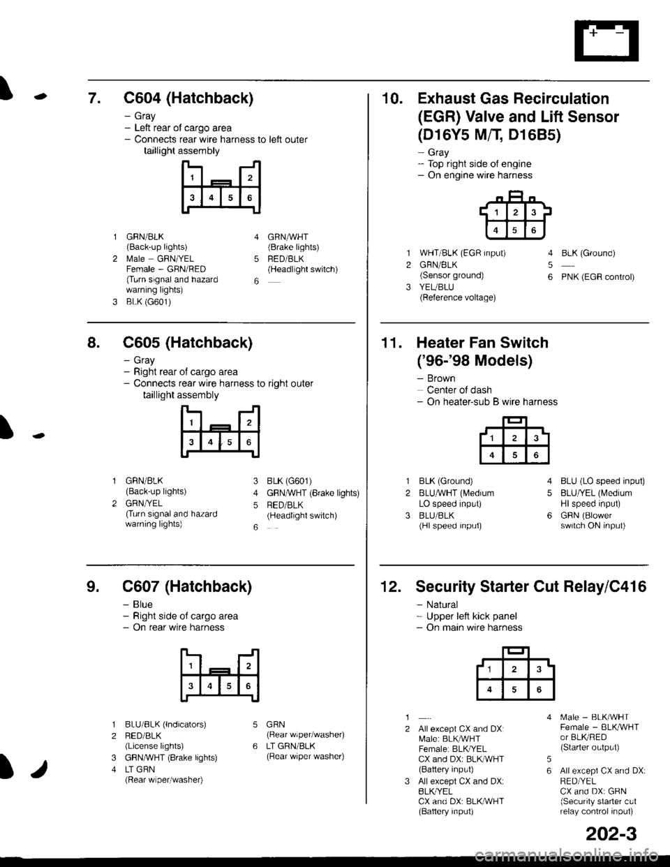
\7. C604 (Hatchback)
GRN/BLK(Back-up lights)
l\4ale GRNIYELFemale - GRN/RED(Turn signaland hazardwarning lights)
BLK (G601)
- Gray- Left rear ol cargo area- Connects rear wire harness to left outer
taillight assembly
4
5
6
1
2
GRNAVHT(Brake lights)
FED/BLK(Headllght switch)
10. Exhaust Gas Recirculation
(EGR) Valve and Lift Sensor
1
2
3
(D16Y5 MfI D1685)
- Gray- Top right side of engine- On engine wire harness
WHT/BLK (EGR input)
GRN/BLK(Sensor ground)
YEUBLU(Reference voltage)
4
5
6
BLK (Ground)
PNK (EGR control)
of cargo area
rear wire harness to right outer
assembly
n- -n
a t | _ a2a
l3I4t5tttl
IJ
I
8. C605 (Hatchback)
- Gray- Right rear- Connects
taillight
GRN/BLK(Back-up lights)
GRNTYEL(Turn signaland hazardwarning lights)
3
4
5
6
1
2
BLK (G601)
GFNAVHT (Brake lights)
RED/BLK(Headlight switch)
11. Heater Fan Switch
('96-'98 Models)
- Brown
Center of dash- On heater-sub B wire harness
BLK (Ground)
BLUAVHT (L4edium
LO speed input)
BLU/BLK(Hl speed input)
4
5
6
1
2
3
BLU (LO speed input)
BLU/YEL (Medium
Hlspeed input)
GFIN (Blowerswitch ON input)
9. C607 (Hatchback)
- Blue- Right side o{ cargo area- On rear wire harness
BLU/BLK (lndicators)
RED/BLK(License lights)
GBN,ryVHT (8rake lights)
LT GBN(Rear wiper/washe0
5
6
1
2
3
4
GRN(Rear wiper/washer)
LT GRN/BLK(Rear \/iper washer)
)/
202-3
12. Security Starter Cut Relay/C416
- Natural* Upper left kick panel- On main wire harness
1
2Allexcept CX and DXI[,4ale: BLK,^r'r'HTFemale: BLKI/ELCX and DXi BLI(WHT(Battery input)
All except CX and DX:BLK^/ELCX and DX: BLK/WHT(Baftery input)
[.4ale - BLK/WHTFemale - BLKAVHTor BLKRED(Starter output)
All excepi CX and DX:RED/YELCX and DX: GRN(Security starter c!1relay control inpul)
5
6
tl3'
Page 2115 of 2189
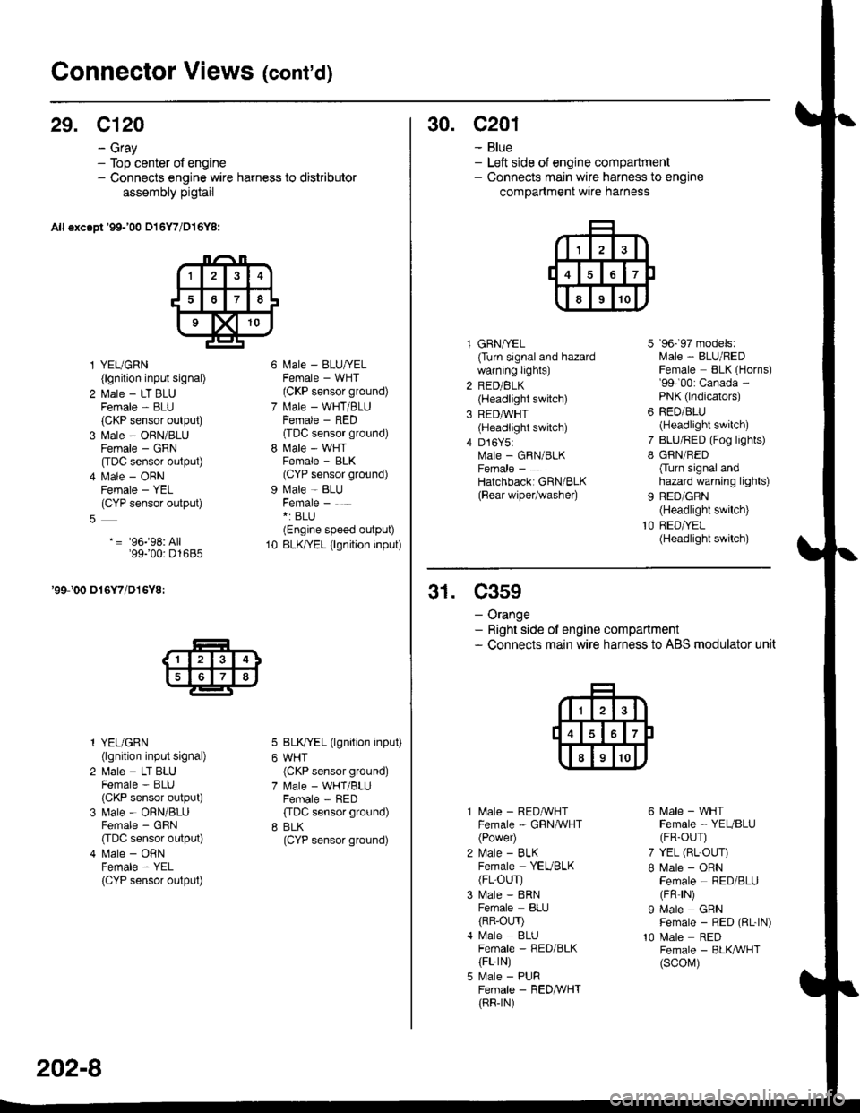
Connector Views (cont'd)
29. C120
- Gray- Top center of engine- Connects engine wire harness to distributor
assembly pigtail
All except '99-'00 016Y7/D16Y8:
l YEUGRN(lgnition input signal)
2 l\.4ale - LT BLUFemale - BLU(CKP sensor output)
3 Male - ORN/BLUFemale - GRN
[tDC sensor output)
4 l\.4ale - ORNFemale - YEL(CYP sensor output)
-= '96j98: All'99100: D1685
'99-'00 016Y7/D16Y8:
l YEUGRN(lgnition input signal)
2 Male - LT BLUFemale - BLU(CKP sensor output)
3 Male - ORN/BLUFemale - GRN
CIDC sensor output)
4 Male - ORNFemale - YEL
{CYP sensor output)
l\4ale - BLU/YELFemale - WHT(CKP sensor ground)
l\.4ale - WHT/BLUFCMAIE _ HtsL'(TDC sensor ground)
l\4ale - WHTFemale - BLK(CYP sensor ground)
Male - BLUFemale - . -*: BLU(Engine speed output)
BLK/YEL (lgnition input)
BLK/YEL (lgnition input)
WHT(CKP sensor ground)
Male - WHT/BLUFemale - RED
ffDC sensor ground)
BLK(CYP sensor ground)
10
202-8
30. c201
- Blue- Left side of engine compartment- Connects main wire harness to engine
compartment wire harness
l GRNA/EL(Turn signal and hazardwarning lights)
2 RED/BLK(Headlight switch)
3 REDAVHT(Headlight switch)
4 D16Y5:Male - GRN/BLKFemale -
Hatchbacki GRN/BLK
{Bear wipetwashe0
7
I
9b- 9/ mooets:lvlale - BLU/REDFemale BLK (Horns)'99-'00: Canada -
PNK (lndicators)
RED/BLU(Headlight switch)
BLU/RED (Fog lights)
GRN/RED
Cturn signal andhazard warning lights)
BED/GRN(Headlight switch)
RED/YEL(Headlight switch)
31. C359
- Orange- Right side ot engine compartment- Connects main wire harness to ABS modulator unit
10
l\4ale - REDAVHTFemale - GRNA/VHT(Power)
l\,4ale - BLKFemale - YEVBLK(FL-OUr)
Male - 8RNFemale BLIJ
{RR-OLrr)l\4ale BLUFemale - RED/BLK(FL-rN)
Male - PURFemale - RED&VHT(RR-rN)
6 Male - WHTFemale - YEUBLU(FR-OUr)
7 YEL (RL-OUr)
I Male - ORNFemale - RED/BLU(FR rN)
I Male GRNFemale - RED (RL-|N)
10 Male REDFemale - BLK,ryVHT(scol\,1)
Page 2116 of 2189
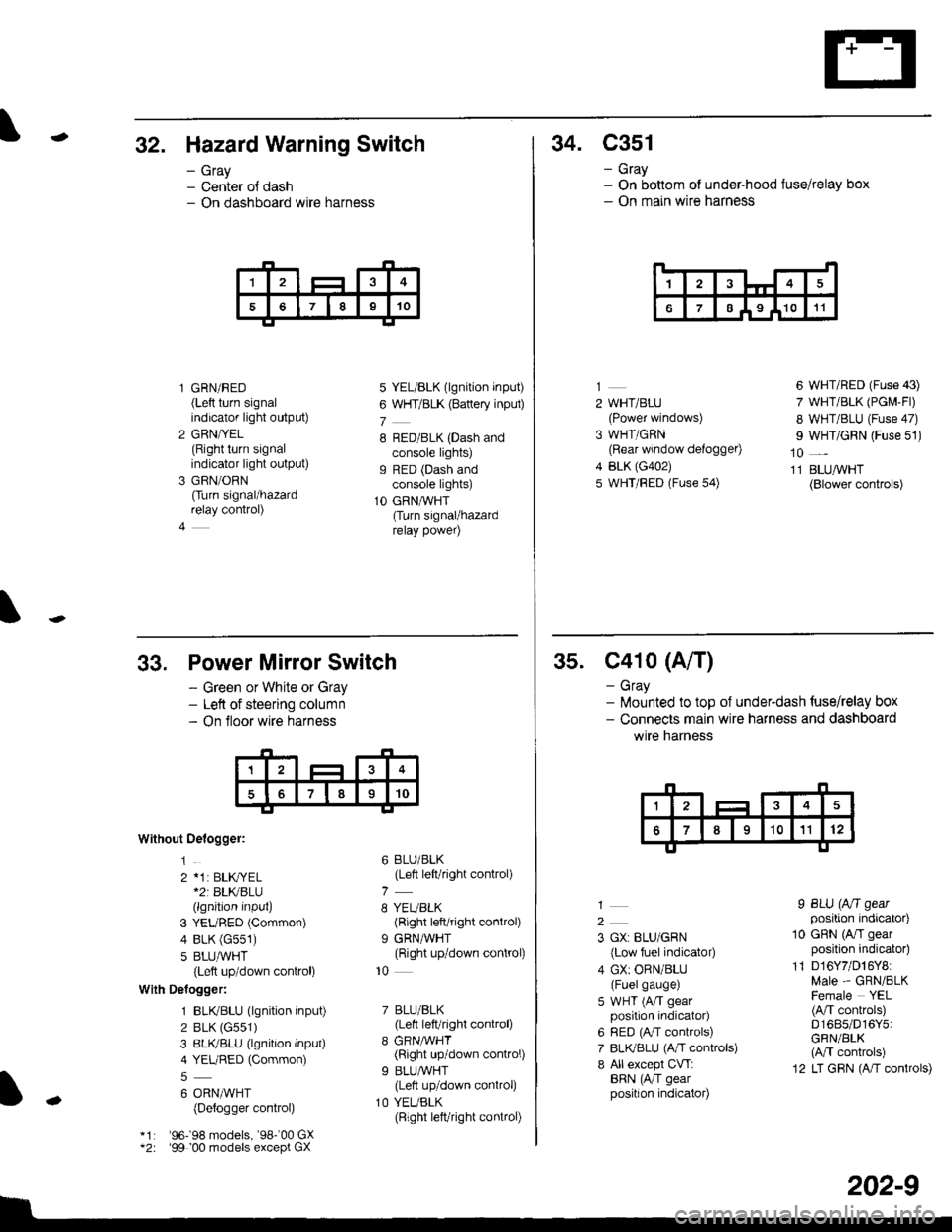
-32. Hazard Warning Switch
- Gray- Center ol dash- On dashboard wire harness
l GRN/RED(Left turn signalindicator light output)
2 GRN/YEL(Right turn signalindicator light output)
3 GRN/ORN
Ourn signal/hazardrelay control)
4
5 YEL/BLK (lgnition input)
6 WHT/BLK (Battery inpul)
7
8 RED/BLK (Dash andconsole lights)g RED (Dash andconsole lights)
1O GRNAVHT(Turn signal/hazardrelay power)
34. C351
- Gray- On bottom of under-hood fuse/relay box- On main wire harness
14
67I I9 I1011
2 WHT/BLU(Power windows)
3 WHT/GRN(Rear window defogger)
4 BLK (G402)
5 WHT/FED (Fuse 54)
6 WHT/RED (Fuse 43)
7 WHT/BLK (PGM-Fl)
8 WHT/BLU (Fuse 47)
I WHT/GRN (Fuse 51)
10 _
11 BLUAVHT(Blower controls)
33,
Without Oelogger:
1
2 *1: BLK,|YEL*2r BLKBLU(lgnition input)
3 YEURED (Common)
4 BLK (G551)
5 8LU,ryVHT(Left up/down control)
With Delogger:
1 BLIVBLU (lgnition input)
2 BLK (G551)
3 BLIVBLU (lgnition inPut)
4 YEURED (Common)
6 ORNMHT(Detogger control)
'96198 models, '98-'00 GX'99 00 models except GX
Power Mirror Switch
- Green or White or Gray- Left of steering column- On floor wire harness
6 BLU/BLK(Left left/right control)
8 YEUBLK(Right left/right control)
9 GRNAVHT(Right up/down control)
10
7 BLU/BLK(Lett left/right control)
8 GRNMHT(Right up/down control)
9 BLU/WHT(Lett up/down control)
1O YEL/BLK(Right left/right connol)
I
-
202-9
35. C41o (A/T)
- Gray- lilounted to top of underdash {use/relay box- Connects main wire harness and dashboard
wtre narness
2
3 GX: BLU/GRN
{Low fuel indicator)
4 GX: ORN/BLU(Fuelgauge)
5 WHT (A/T gearposition indicator)
6 RED (A,/T controls)
7 BLI(BLU (A,rT controls)
8 All except CVT:BRN (AiT gearposition indicator)
I BLU (Aft gearposition indicator)
10 GRN (A/I gearposition indicator)
11 D16Y7/D16Y8:Male - GRN/BLKFemale YEL(A/T conkols)D1685/D16Y5:GRN/BLK(M controls)
12 LT GRN (A/T controls)
Page 2119 of 2189
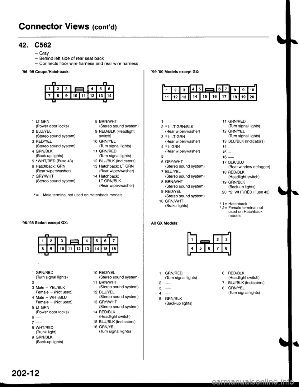
Connector Views (conrd)
42. C562
- Gray- Behind left side ol rear seat back- Connects floor wire harness and rear wire harness
'96-'98 CouDe/Hatchbaqk:
* = Male terminal not used on Hatchback models
'96-'98 Sedan except GX:
1 LT GRN(Power door locks)
2 BLU/YEL(Stereo sound system)
3 RED/YEL(Stereo sound system)
4 GRN/BLK(Back-up lights)
5 *WHT/BED (Fuse 43)
6 Hatchback: GRN(Rear wiper/washer)
7 GRYAVHT(Stereo sound system)
l GRN/RED(Turn signal lights)
2_
3 l,4ale - YEUBLKFemale - (Not used)
4 ftrale - WHT/BLUFemale - {Not used)
5 LT GRN(Power door locks)
8 WHT/RED(Trunk light)
9 GRN/BLK(Back-up lights)
8 BRNMHT(Stereo sound system)
9 RED/BLK (Headlight
switch)
1O GFN/YEL(Turn signal lights)
l1GRN/RED
Ourn signal lights)
12 BLU/BLK (lndicators)
13 Hatchback: LT GBN(Rear wiper/washer)
14 Hatchback:LT GRN/BLK(Rear wiper/washer)
1O RED/YEL(Stereo sound system)
11 BRNA,ryHT(Stereo sound system)
12 BLU/YEL
{Stereo sound system)
13 GRYA/VHT
{Stereo sound system)
14 RED/8LK(Headlight switch)
15 BLU/BLK (lndicators)
16 GRN/TEL(Turn signallights)
202-12
'99-'00 Models exceDl GX:
1
2 11: LT GRN/BLK(Rear wiper/washe0
3 *1: LT GRN(Rear wiper/washe0
4 a1r cRN(Rear wiper/washe0
6 GRYMHT(Stereo sound system)
7 BLU/YEL(Stereo sound system)
8 BRN,^/VHT(Stereo sound system)
9 REDA/EL(Stereo sound systern)
10 GRN,^/VHT(Brake lights)
All GX Models:
GRN/RED(Turn signal lights)
GBN/BLK(Back-up lights)
11 GRN/RED(Turn signal lights)
12 GRN/YEL
Ourn signal lights)
13 BLU/BLK (lndicators)
14
16
17 BLI(BLU(Reaf window defogger)
18 RED/BLK(Headlight switch)
19 GRN/BLK(Back-up lights)
20 *2: WHT/FED (Fuse 43)
* 1 = Hatchback* 2= Female terminal notused on Hatchbackmooers
RED/BLK(Headlight switch)
BLU/BLK (lndicators)
GRN/YEL(Turn signal lights)
6
7
I
2
3
4
5
'I24t56I7I910
't11214151617't81920
Page 2121 of 2189
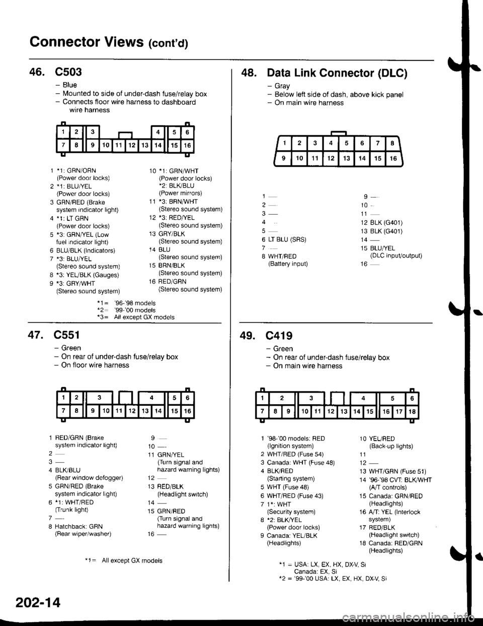
Gonnector Views (conrd)
46. C503
B
9
*1: GBN/ORN(Power door locks)*1r BLU|/EL(Power door locks)
GRN/RED (Brake
system indicator light)*1r LT GRN(Power door locks)*3: GRN/YEL (Lowfuel indicator light)
BLU/BLK (lndicators)*3: BLU/YEL(Stereo sound system)*3: YEUBLK (Gauges)*3: GRY/WHT(Stereo sound system)
10 *1: GRNAVHT(Power door locks)*2: BL(BLU(Power mirfors)
11 *3: BRNMHT(Stereo sound system)
12 *3: RED/YEL(Stereo sound system)
13 GRY/BLK(Stereo sound system)
14 BLU(Stereo sound system)
15 BRN/BLK(Stereo sound system)
16 RED/GBN(Stereo sound system)
- Blue- lvlounted to side of under-dash fuse/relay box- Connects floor wire harness to dashboardwtre narness
1
2
3
5
6
7
*1= '96-'98 models*2: '99-'00 models*3= All except GX models
48. Data Link Connector (DLC)
- Gray- Below left side of dash, above kick panel- On main wire harness
4
6 LT BLU (SRS)
7
8 WHT/BED(Battery input)
9
10
12 BLK (G401)
13 BLK (G401)
14
15 BLU/YEL(DLC inpuVoutput)
47. C551
- Green- On rear of under-dash tuse/relay box- On floor wire harness
1 BED/GRN (Brake
system indicator light)
2
4 BLI(BLU(Rear window defogger)
5 GBN/RED (Brake
system indicator llght)
6 *1: WHT/RED(Trunk light)
7
8 Hatchback: GBN(Rear wiper/washer)
9
10
11 GRN/YEL(Turn signal andhazard warning lights)
13 RED/BLK(Headlight switch)
14
15 GRN/RED(Turn signal andhazard warning lights)
202-14
*1= Allexcept GX models
49. C419
- Green- On rear of under-dash fuse/relay box- On main wire harness
1 '98''00 models: RED(lgnition system)
2 WHT/RED (Fuse s4)
3 Canada: WHT (Fuse 48)
4 BLI(RED(Starting system)
5 WHT (Fuse 48)
6 WHT/RED (Fuse 43)
7 1*: WHT(Security system)
I *2: BLK,TYEL
{Power door locks)
I Canada: YEL/BLK(Headlights)
1O YEURED(Back up lights)
11
13 WHT/GRN (Fuse 51)
14 '96-'98 CVT: BLKWHT(A/T controls)
15 Canada: GRN/RED(Headlights)
16 A/Ti YEL (lnterlock
system)
17 RED/BLK(Headlight switch)
18 Canada: RED/GRN(Headlights)
"1 = USA: LX, EX, HX, DX-V SiCanada: EX, Si12 = '99100 USA: LX, EX, HX, DX-V Si
Page 2122 of 2189
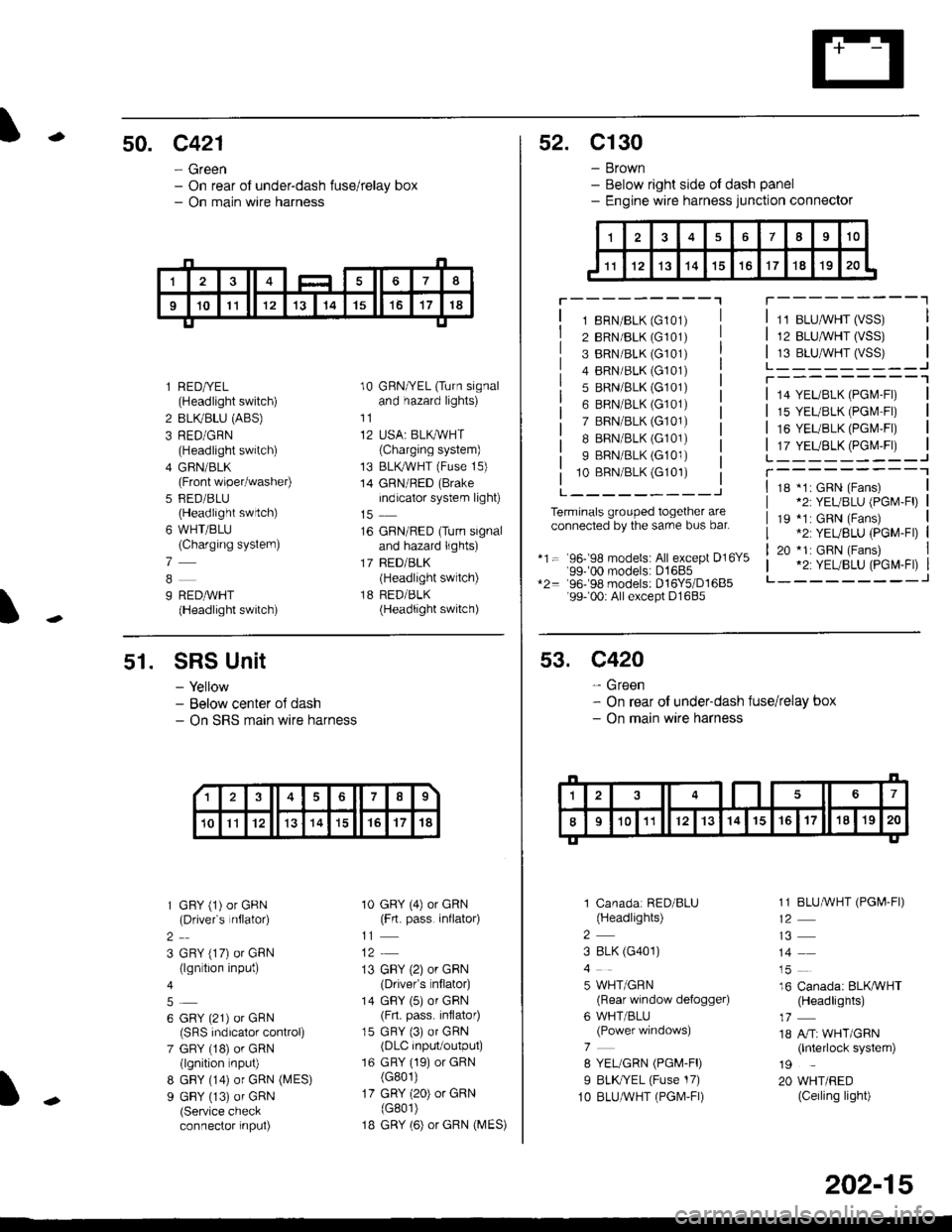
-50. c421
- Green- On rear of under-dash fuse/relay box- On main wire harness
I
l RED/YEL(Headlight switch)
2 BLIVBLU (ABS)
3 RED/GRN(Headlight switch)
4 GFIN/BLK(Front wiper/washer)
5 FED/BLU(Headlight swrtch)
6 WHT/BLU(Charging systern)
7
9 REDAVHT(Headlight switch)
10 GRN/YEL (Turn signaland hazard lights)
11
12 USA: BLKAVHT(Charging system)
13 BLKryVHT (Fuse 15)
14 GRN/RED (Brake
indicator system light)
16 GRN/RED (Turn signaland hazard lights)
17 BED/BLK(Headlight switch)
18 RED/BLK(Headlight switch)
52. C130
- Brown- Below right side ot dash panel- Engine wire harness junction connector
T---------"1
1 8RN/BLK (G101)
2 BRN/BLK (G101)
3 BRN/BLK (G101)
4 BRN/BLK (G101)
5 BRN/BLK (G101)
6 BRN/BLK (G101)
7 BRN/BLK (G101)
I BRN/BLK (G101)
9 BRN/BLK (G101)
10 BBN/BLK (G101)
L---------J
Terminals grouped together areconnected by the sarre bus bar.
*1= 96- 98 models: All except D16Y5'99-'00 models: D1685*2= 96-98 models: D16Y5/D1685'99- 00r All except D1685
11 BLUMHT (VSS)
12 BLU,ryVHT (VSS)
13 BLU,^/VHT (VSS)L_-_____--Jr---------'1
14 YEL/BLK (PGl\4-Fl)
15 YEL/BLK (PGr\4'Fr)
16 YEUBLK (PGI\4,FI)
17 YEUBLK (PGr\4,Fr)L______---JT----------118 *1: GRN (Fans)*2: YEUBLU (PGM-Fl)
19 *1: GRN (Fans).2: YEUBLU (PGM-Fl)
20 *1: GRN (Fans).2: YEUBLU (PGM-Fl)_______--J
51. SRS Unit
- Yellow- Below center oJ dash- On SRS marn wire harness
1 GFY (1) or GRN(Drivefs nflator)
2
3 GRY (17) or GRN(lgn tion input)
6 GRY (21) or GRN(SRS indicalor control)
7 GRY (18) or GRN(lgnition nput)
8 GBY (14) or GRN (MES)
9 GBY (13) of GRN(Service checkconnector input)
10 GRY (4) or GRN(Frt. pass. inflato4
11
13 GBY (2) or GRN(Drivefs nflator)
14 GBY (5) or GRN(Frt. pass. inflator)
15 GRY (3) or GRN(DLC input/output)
16 GRY (19) or GRN(G801)
17 GRY (20) or GRN(G801)
1B GRY (6) or GRN (MES)
13678
10Il12131415't7't8
53. C420
- Green- On rear of under-dash fuse/relay box- On main wire harness
1 Canadar RED/BLU(Headlights)
2
3 8LK (G401)
5 WHT/GRN(Rear window defogger)
6 WHT/BLU(Power windows)
7
8 YEL/GRN (PGM-FD
I BLK//EL (Fuse 17)
1O BLUAVHT (PGM,FI)
1 1 BLUMHT (PGI,4-FI)
14
16 Canada: BLKAVHT(Headlights)
18 A/Tr WHT/GRN(lnterlock system)
19
20 WHT/RED(Ceiling light)
202-15