2000 HONDA CIVIC tow
[x] Cancel search: towPage 1662 of 2189
Stereo Sound System
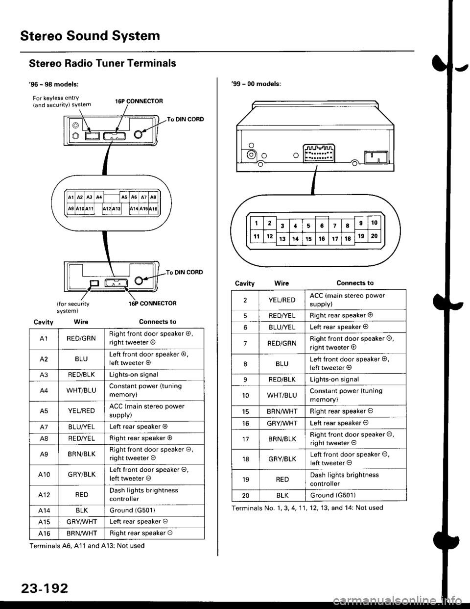
Stereo Radio Tuner Terminals
'96 - 98 models:
For keyless entry . t6p coNNEcroR(and securrty) syslem
To DIN CORD
To DIN CORD
(for securitysystem)
Cavity Wire
A1RED/GRNRight front door speaker o,
right tweeter @
BLULeft front door speaker @,
left tweeter @
A3RE D/B LKLights-on signal
A4WHT/BLUConstant power (tuning
memoryl
A5YEL/REDACC (main stereo power
suppry)
A7BLUI/ELLeft rear speaker O
A8RE DI/E LRight rear speaker O
A9BRN/BLKRight front door speaker O,
right tweeter o
A10GRY/BLKLeft tront door speaker O,
left tweeter O
412REDDash lights brightness
controller
A14BLKGround (G501)
415GRYMHTLeft rear speaker O
Al6BR N/VVHTRight rear speaker O
Terminals A6, A11 and A13: Not used
23-192
'99 - 00 models:
CsvityConnccts toWire
2YEL/REDACC (main stereo power
suppry)
5RE DI/E LRight rear speaker @
BLUI/ELLeft rear speaker @
7RED/GRNRight front door speaker @,
right tweeter @
8BLULeft front door speaker @,
left tweeter @
9RED/BLKLights-on signal
10WHT/BLUConstant power (tuning
memory)
15BRN,ryVHTRight rear speaker O
GRYMHTLeft rear speaker O
17BRN/BLKRight front door speaker O,
right tweeter O
18G RY/BLKLeft front door speaker O,
left tweeter O
'19REDDash lights brightness
controller
20BLKurouno t(l5u t,
Terminals No. 1, 3, 4, 11,12, 13, and 14: Not used
Page 1683 of 2189
7.
8.
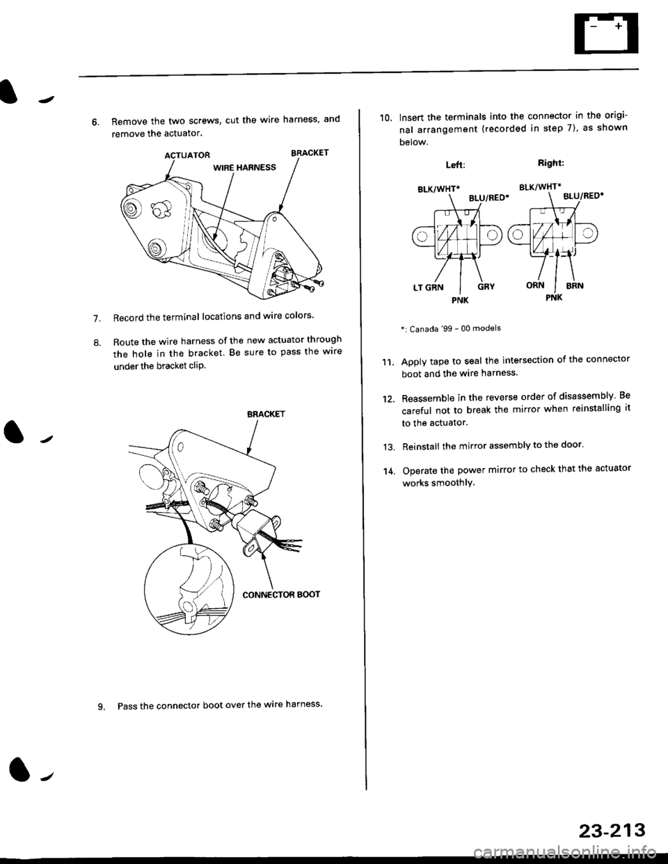
6. Remove the two screws, cut the wire harness, and
remove the actuator.
Record the terminal locations and wire colors'
Route the wire harness of the new actuator through
the hole in the bracket. Be sure to pass the wlre
under the bracket cliP.
BRACKET
9. Pass the connector boot over the wire harness
23-213
BLK/WHTi
,t
L,
.;{
I
oa
LT GRN I GRY
PNK
10, lnsert the terminals into the connector in the origi-
nal arrangement (recorded in step 7), as shown
Detow.
Right:
SLK/WHT*
BLU/REO'
": Canada '99 - 00 models
Apply tape to seal the intersection of the connector
boot and the wire harness.
Reassemble in the reverse order of disassembly Be
careful not to break the mirror when reinstalling it
to the actuator.
Reinstall the mirror assembly to the door.
Operate the power mirror to check that the actuator
works smoothlY.
Left:
11.
12.
13.
't 4.
PNK
Page 1748 of 2189
Preca utions/Procedures
Spring-loaded Lock Connector
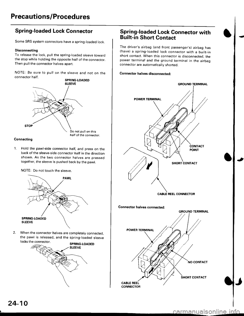
Some SRS system connectors have a spring-loaded lock.
Disconnecting
To release the lock, pull the spring-loaded sleeve towardthe stop while holding the opposite half of the connecror.Then pull the connector halves apart.
NOTE: Be sure to pull
connector half.
on the sleeve and not on the
SPRING-LOADEOSLEEVE
Do not pull on thishalf of the connector.
Connecting
1. Hold the pawl-side connector half, and press on theback of the sleeve-side connector half in the directionshown. As the two connector halves are pressed
together, the sleeve is pushed back by the pawl.
NOTE: Do not touch the sleeve.
When the connector halves are completely connected,the pawl is released, and the spring-loaded sleevelocks the connector.SPRING.LOADEDSLEEVE
24-10
Spring-loaded Lock Connector with
Built-in Short Contact
The driver's ajrbag (and front passenger,s) airbag has(have) a spring-loaded lock connector with a builr-inshort contact. When this connector is disconnected, thepower terminal and the ground terminal in the airbaaconnector are automatically shoned.
Connector halves disconnected:
SHORT CONTACT
Conneqtor halves connected:
GROUND TERMINAL
CABLE REEL CONNECTOR
GROUND TERMINAL
Page 1814 of 2189
SRS Unit
Replacement
CAUTION:
. Betore disconnoqting lny pErt of the SRS wire hal-ness, disconnect th9 airbag conn"ctorlsl.. During installltion or teplacemsnt. do not bump(impact w.cnch, hamm€r stc.l the area noar tho SRSunit.
NOTE:
o Do not damage the SRS unit terminals or connectors.. Do not disassemble the SRS unit; it has no service-able parts,
. Store the SRS unit in a clean, dry a.ea,. Do not use any SRS unit which has be€n subjected towater or shows signs of being dropped or improperlyhandled. such 8s dents, cracks or deformation.
1. Disconnect the bsttery negative cable. then discon-nect the positive cable from the battery, and wait atleast three minutes.
2. Disconnect the airbag connector{s}:
NOTE: When disconnected, the airbag connector isautomatically shorted,
Driver's Side:
. Remove the access panel from the steering wheel.then disconnect the 2P connector between the driv_er's airbag and cable reel (see page 24-11).
Front Passenge/s Side:. Disconnect the 2P connector between the tront oas_senger's airbag and SRS main harness (see page 24-11).
24-76
o\
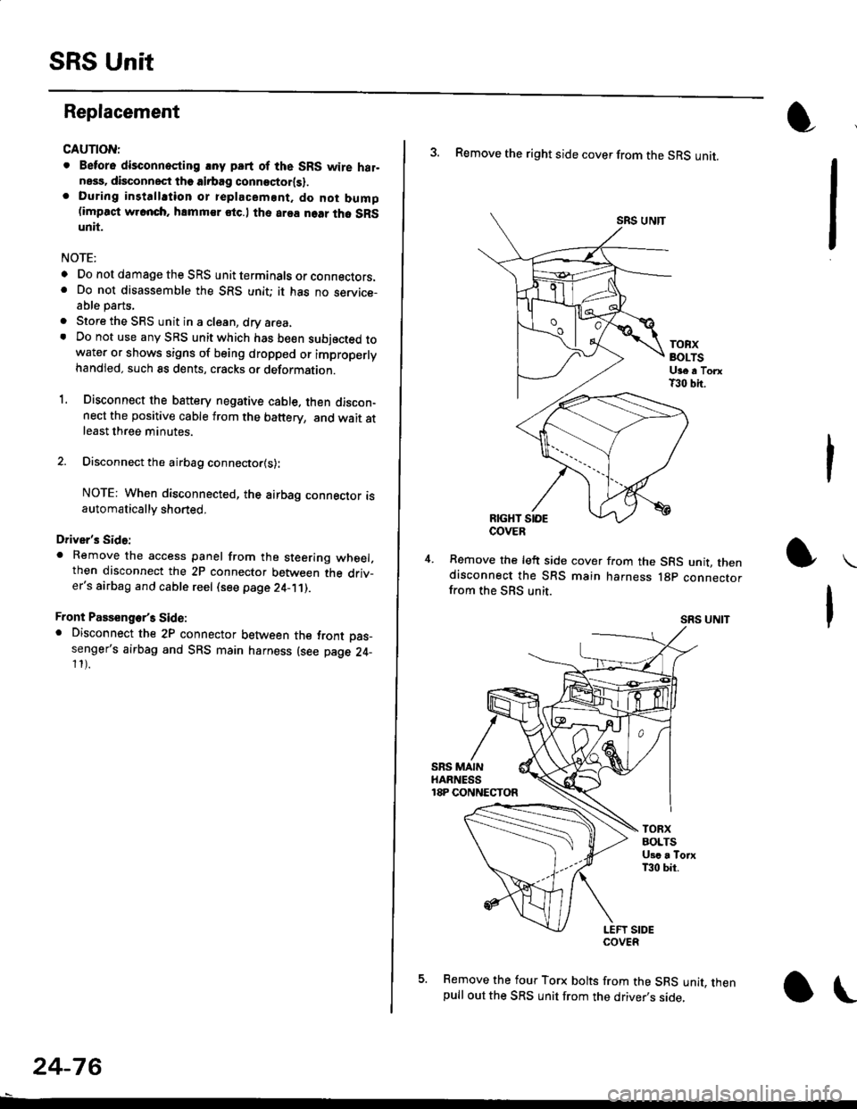
3. Remove the right side cover from the SRS unit.
SRS UNTT
TOBXBOLTSUge a TorxT30 bit.
RIGHT SIOE
Remove the left side cover from the SRS unit, thendisconnect the SRS main harness lgp connectorfrom the SBS unit.
SRS UNIT
5. Remove the four Torx bolts from the SRS unit, thenpull out the SRS unit from the driver,s side,
COVER
Page 1819 of 2189
How To Use This Manual
Circuit Schematics
oa
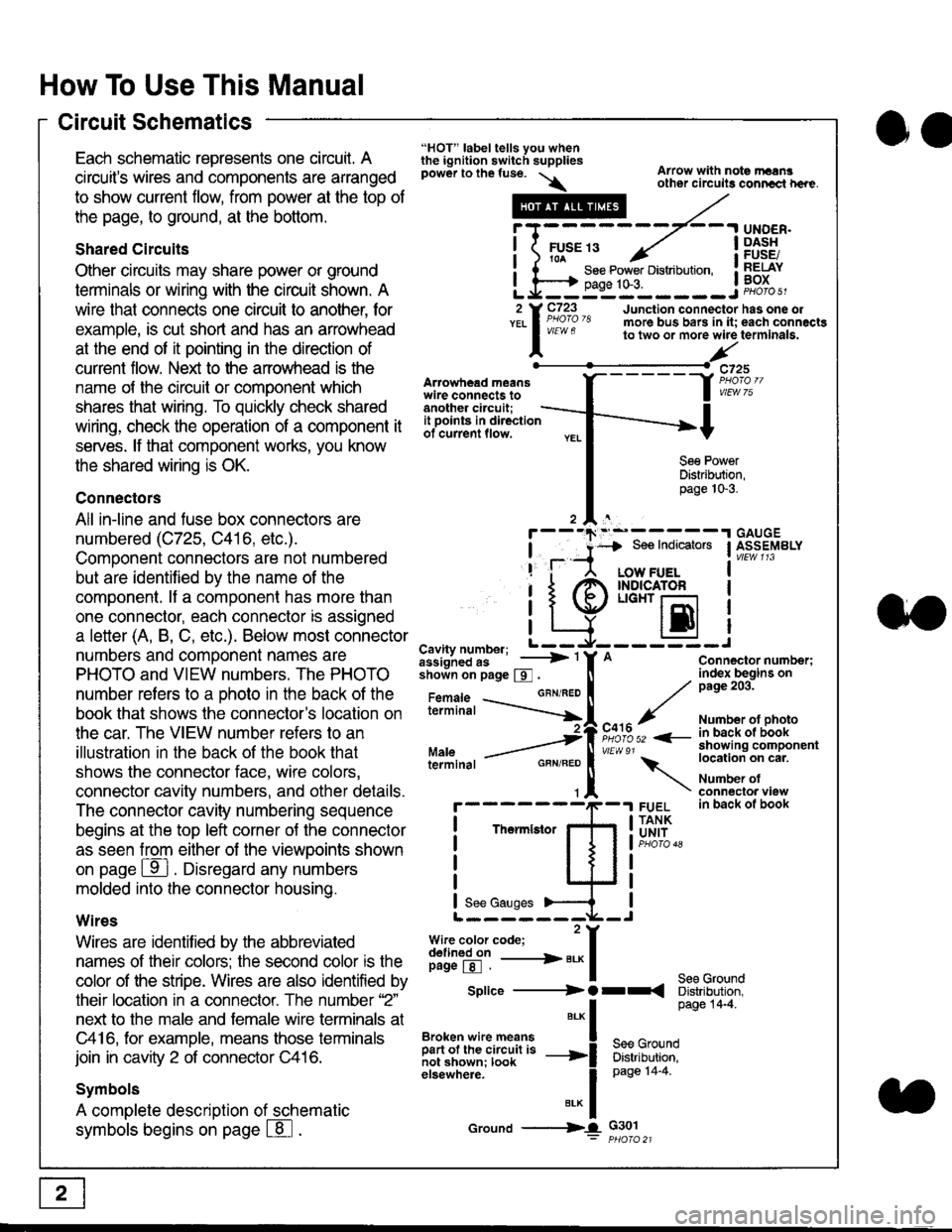
Each schematic represents one circult. A
circuit's wires and components are arranged
to show current flow, from power at the top of
the page, to ground, at the bottom.
Shared Circuits
Other circuits may share power or ground
terminals or wiring with the circuit shown. A
wire that connects one circuit to another, for
example, is cut short and has an arrowhead
at the end of it pointing in the direction of
current flow. Nelit to the anowhead is the
name o{ the circuil or comoonent which
shares that wiring. To quickly check shared
wiring, check the operation of a component it
serves. lf that component works, you know
the shared wiring is OK.
Connectors
All in-line and fuse box connectors are
numbered (C725, C416, etc.).
Component connectors are not numbered
but are identiJied by the name of the
component. lf a componenl has more than
one connector, each connector is assigned
a letter (A, B, C, etc.). Below most connector
numbers and comDonent names are
PHOTO and VIEW numbers. The PHOTO
number refers to a Dhoto in the back of the
book that shows lhe conneclor's location on
the car. The VIEW number refers to an
illustration in the back of the book that
shows the connector face, wire colors,
connector cavity numbers, and other details.
The connector cavity numbering sequence
begins at the top left corner oJ the connector
as seen from either of the viewooints shown
on page ffl . Disregard any numbers
molded into the connector housino.
Wires
Wires are identilied by the abbreviated
names of their colors; the second color rs the
color of the stripe. Wires are also identified by
their location in a connector. The number '2"
next to the male and female wire terminals at
C416, for example, means those terminals
join in cavity 2 of connector C416.
Symbols
A complete description of schematic
symbols begins on page | 8
"HOT" label tells you whenthe ignition switch suppliespower to the fuse. \
Artowhead meanswire connects toanother circuit;
Arrow with note rErngother circuils conncct h€re.
it .a
llu":: ^,{ ii t See Power Distribution, .I t----t oaqe tO-3. IL*--:--------J2 Y C723 Junction connectorYEL I Pao'o'8 more bus bars in it;
I - " " to two or more wire
l,/
-t>?
See PowerDistribution,page 10-3.
UNDER.DASHFUSE/RELAYBOX
has one oleach connactgterminala.
it ooints in directionof current flow.
TheImletor
t_I
Cavity number; L ---
Jiili'iJi!--' -----> '
shoin on page S .
Maleterminal
L?*?l?,-
"'"'I
c725
vlEUt/ 75
Connector number;index begins onpage 203.
Number ot photoin back ol bookshowing componentlocation on cat.
Number ofconneclor viewin back of book
7
GBN/FEO
See Ground
Soe Indicators I ASSEMBLY
:-------J
LOW FUELINDICATOFLIGHT r-l
EI
A
"o'r"/PHOTO 52 <-
\
FUELTANKUNIT
Splice ---------) O rr
".* I Page 14'4'
IBroken wire means | --^ -
iar";J.'It,;,rJ;ii; -----i Bffi,Bili*l
elsewhere. I 0a0e tn-a
IBrK Icround --->lL c301: ptioro 21
Page 1875 of 2189
- Automatic Transmission (All except Dl685)
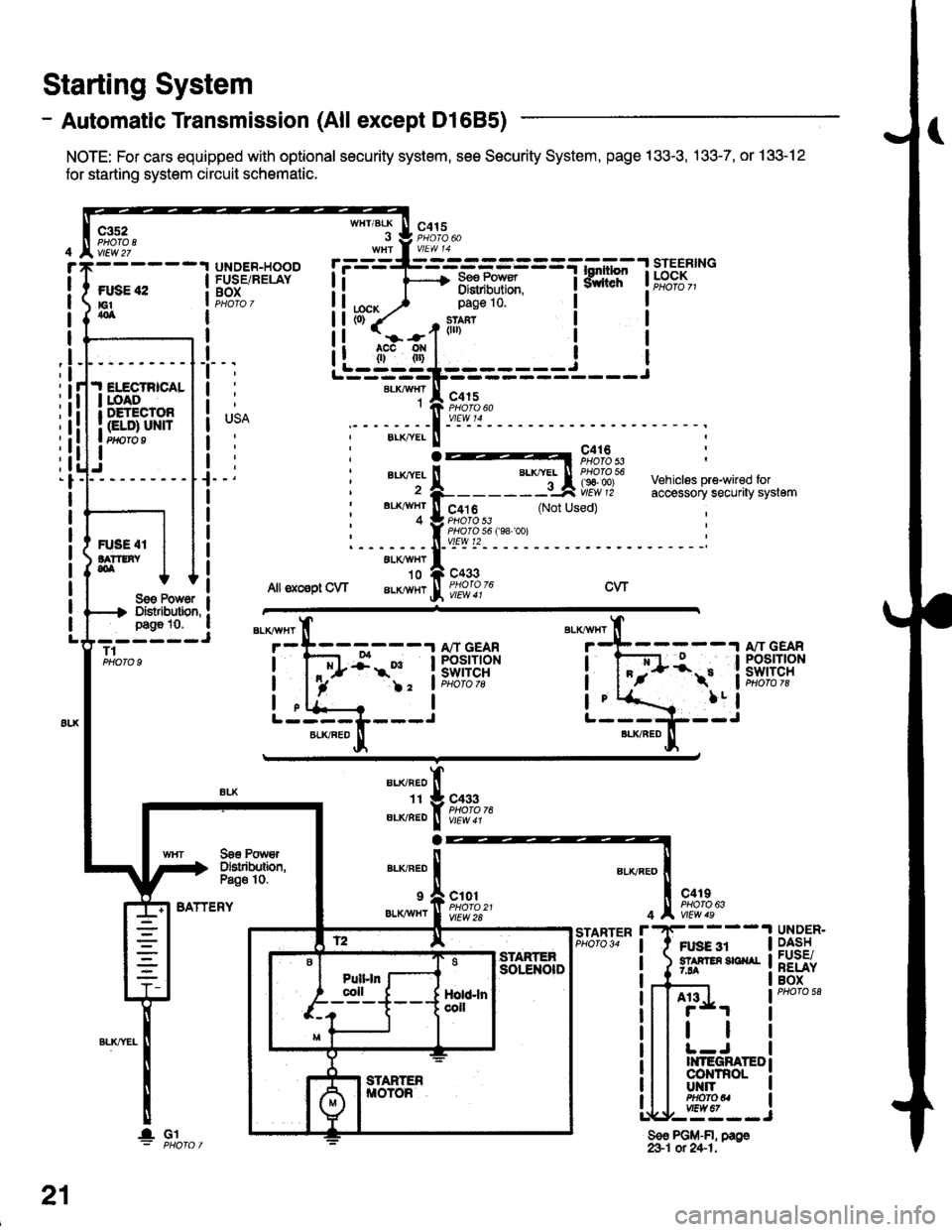
NOTE: For cars equipped with optional security system, see Security System, page 133-3, .133-7, or 133-12
for starting system circuit schomatic.
Starting System
c3s2PHO|O IvlEw 27
ftxiE "2E1404
WHT/BLK
I
lta":
c415
=-mF,Uf.
--l
9,lLT i ld;f,,"-
I
I
It
I
I
I
I
I
I
I
I
pag€ 10.
slan?(ll)
c415
I
Ji.I ELECTRICALI roAoI DETECTOR
I Gt ol ulra Ptfifo I
IJ
BLKAIVHT1
ELK./YEL
au(|vEL
BL'(4I/HT
4
c416PHOTO 53
c4t 6PHO|O 53PHO|O 56 f98 '�oo)vtEw t2
c433
Vehiclss pre-wired foraccessory securaty system(Not Used)
R'SE 4IlA??tNY,olALXAVHY'10
Allsxcsptow aLKlvHrcwSoe Pow6r IDistibution, !page 10. a- ----JT1PHOTO 9
BATTERY
BLKAVHT
7
L-----L---JBLKFED
13:;-1ifl;ft?R
!-
)2 'lPHoto tg
a
BLI(RED
1I
ELIVBED
ALKNED
c433PHOTO 76
Soe PowrDslributbn,Pa€o 10.
9 a c101
er.xiwxr I ffo,rtfl'�t
c4rIPHO|O 63
Ft gg 3r5? F En 3E ^r7.94
4
r'STARTERPHO|O 34UNDER.DASHFUSE/RELAYBOX
A13
tl
II{TEGRATEDco|{TnoLUT{ITPHOfOUvtEw 67,--==--J
Sso PGM-FI, page&1 ot 24-1.
21
lGl
Page 1980 of 2189
Gauges (cont'd)
- How the Gircuit Works
When the ignition switch is in ON (ll) or START (lll),
battery voltage is supplied through fuse 25 to the
gauges in the gauge assembly.
Speedometer and Odometer
The odometer and soeedometer drive circuits
receive pulses from the vehicle speed sensor
(VSS). The pulse rate increases as the car
accelerates. The frequency and duration of these
input pulses are measured and displayed by the
speedometer, odometer and tripmeter.
Tachometer
The tachometer drive circuit receives pulses from
the ignition control module (lCM) in the distributor
assembly or the ECM/PCM. The solid-state
lachometer then displays these pulses as engine
speed. For each 200 pulses per minute from the
ignition control modul€ (lCM) or the ECM/PCM, the
tachometer displays 100 RPM.
Engine Coolant Temperature Gauge
The engine coolant temperature gauge has two
intersecting coils wound around a permanent
magnet rotor. Voltage applied to the coils, through
fuse 25, generates a magnetic lield. The magnetic
field, controlled by the coolant temperature sending
unit, causes the rotor to rotate and the gauge
needle to move. As the resistance in the sending
unit varies, current through the gauge coils
changes. The gauge needle moves toward the coil
with the strongest magnetic field.
The 6ngine coolant temperature sending unit's
resistance varies from about 137 ohms at low
engine temperature to between 3H6 ohms at high
temperature (radiator fan running).
Refer to the Service Manual (Section 23, Electrical)
for specific tests or troubleshooting procedures.
81-2
(
Fuel Gauge (All except cX)
The fuel gauge has two intersecting coils wound
around a permanent magnet rotor. Voltage applied
to the coils, through tuse 25, generates a magnetic
field. The magnetic field, controlled by the fuel
gauge sending unit, causes the rotor to rotate and
the gauge needle to move. As the resislance in the
sending unit varies, current through the gauge coils
changes. The gauge needle moves toward the coil
with the strongest magnetic field.
The fuel gauge sending unit's resistance varies
from about 2-5 ohms at full, to about 110 ohms at
empty. When you turn the ignition switch off, the
gauge remains at the last reading until you turn the
ignition switch to ON (ll) or START (lll) again,
Refer to the Service Manual (Section 23, Electrical)
for specific tests or troubleshooting procedures.
Fuel Gauge (GX)
The fuel gauge has two intersecting coils wound
around a permanent magnet rotor. Voltage applied
to the coils, through fuse 25, generates a magnetic
field. The magnetic field, controlled by the PCM,
causes the rotor to rotate and the gauge needle to
move. The PCM calculates the gas quantity in the
fuel tank by using the fuel pressure value detected
by the tuel tank pressure sensor and the fuel
temperature value detected by the fuel tank
temperalure sensor, and outputs the signal to the
gauge assembly. The gauge needle moves toward
the coil with the strongest magnetic field.
When you turn the ignition switch off , the gauge
remains at the last reading until you turn the ignition
switch to ON (ll) or START (lll) again. When the
PCM detects a malfunction with the fuel pressure or
temperature, or detects a gas leak, the PCM
reduces the fuel meter to 0.
Refer to the Service Manual GX Supplement
(Section 11 , Fuel and Emissions) for specific tests
or troubleshooting procedures.
a
a
Page 1986 of 2189
Front WiperMasher (cont'd)
- How the Circuit Works
When the ignition switch is in ON (ll) or START (lll),
battery voltage is applied to lhe combination wiper
switch. and the windshield wiDer motor.
Low Speed
When you turn the wiper switch to LO, the wiper
motor's low speed winding is grounded through the
BLU wire and the LO speed contacts of the wip€r
switch at G401, and the wipers run at low speed.
ParUOfl
When you turn the wiper switch OFF, the integrated
control unit (PARK input) grounds the wiper motor
through the BLUMHT wire. The cam switch on the
motor signals the integrated control unit that the
wipers are in the PARK position; the control unit
then removes ground from the motor, and the
wipers stop in the PARK position.
High Speed
When the wiper switch is in Hl, the high speed
windings of the windshield wiper motor are
grounded through the BLUIrEL wire and the Hl
contacts of the wiper switch at G401, and the
wipers run at high speed.
Intermittent
When the wiper switch is in lNT, battery voltage is
applied through the YEUBLU wire to the integrated
control unit (lntermittent wiper ON input). The
integrated control unit (lnt€rmittenvPark Wiper
Control) grounds the low speed windings of the
wiper motor and the wipers make a single sweep
every few seconds (See Low Speed above). When
the wiper retums to the PARK position, the park
switch applies battery voltage through the
BLUMHT wire to the integrated control unit (PARK
input), and the wipers stop in the PARK position.
Mist
When you pull the wiper switch down to MIST
position, the high speed windings ot the wiper motor
are grounded through the BLU^/EL wire and the
closed contacts ot the mist switch at G401, and the
wipers make one pass across the windshield at high
speed. The ParUOff function then takes over and
the wipers stop in the PARK position.
Washel
When you pull the wiper switch toward you to turn
on the washer switch, battery vollage is applied to
the washer motor. The motor pumps fluid onto the
windshield until you release the lever; on '98r99
models, the integrated control unit (windshield
washer ON input) s€nses power at the WHT/BLK
wire terminal and runs the wipers whenever the
washer motor runs.
Refer lo the Service Manual (Seclion 23, Electrical)
for specific tests or troubleshooting procedures.
91-2