Page 1310 of 2189
Rear Seat
Removal (cont'dl
3D:
>: Bolt locationsA>,6
':^2
STRIKERRemove the side t.impanel (see page 20-60).
c>,1
STBIKER
,.:) : Hook locations, 2 >: Clip locations, 14
SEAT CUSHION
STRIKER
6x1.0mm9.8 N.m (1.0 kgI.m,7.2 tbf.ft)
V
RIGHTSEAT-BACK
Pivot bolt constiuction:
TOOTHEOLOCKWASHER
BUSHING
PIVOT
Installation is the reverse of the removal procedure.
NOTE:
Ptvor BoLT BRACKETI x 1.25 mm22 N.m {2.2 kgl.m. 16 lbf.ft)Apply liquid thread lock.
. Beiore anaching the seat-back and seat cushion, make sure there are no twists or kinks in the rear seat belts andcenter belt.
. When installing the seat cushion, slip the seat belt buckles through the slits in the seat cushion.. Make sure the seat-back locks securely.
. lf necessary, adjust the striker and seat-back.
20-ao
6xr.omm I9.8 N.m (1.0 ksf.h,i
@,
EE)qr ,/
6x1omm I22 N.m {2.2 kgf.m,l,"rrr,n2
PIVOTBRACKET
LEFTSEAT.BACK
tt
A
CENTERPIVOT
\---.---
6x1.0mm
BRACKET
B>, 1
e
I
tr
-l:/*- -"HOOK
Page 1311 of 2189
2Dt
>: Bolt locationsa>,6
O : Hook locations. 2 >: Clip location3, 14
SEAT CUSHION
,r@.''----EF-|
EH)w,/
PIVOTBRACKET
BUSXING
PIVOT
PIVOT BOLT BRACKET
I x 1 .25 mm22 N.m (2.2 kgt m. 16lblft)
Apply liquid thread lock.
lnstallation is the reverse of the removal procedure'
NOTE;
.Beforeattachingtheseat-backandseatcushion,makesuretherearenotwistsorkinksintherearseatbe|tsand
center belt.
.wheninsta||ingtheseatcushion,sliptheseatbe|tbucklesthroughthes|itsintheseatcushion.
. Make sure the seat-back locks securely
. lf necessary, adjust the seat-back latch (see page 20-82) and seat-back'
6xr.omm ]9.8 N.m l1.O kgf.m,i,:r:2
B>, 1
ffi
IgIt
c>, 1
6xr.omm I 8r.'r.o-- r22 N.m {2.2 kgtm,' \ffz s.e N.m tr.o *gf.m,'
,r:r",
_) E
7.2rbf.ftl
)
vv
PIVOT BRACKET
RIGHT SEAT.BACK
PIVOT BRACKET
Pivot bolt constauctaon:
TOOTHEDLOCKWASHER
SEAT.BACK MAT
,^
20-41
Page 1312 of 2189
Rear Seat
Seat-back Latch Replacement
2Dl4Dl
Remove the lock cylinder trim, then remove the rear
shelf (see pages 20 59, 61).
NOTE: Take care not to bend each lock rod.
>: Boh, screw locationsA>,4
6x1.0mm9.8 N.m (1.0 kgt.m,7.2 rbf.ftl
LOCK CYLINOERTRIM
.i.-::
LOCKRODS
LEFT SEAT-EACK I-ATCH
Installation is the reverse of the removal procedure.
NOTE:
. Make sure each lock rod is connected securely.. [/ake sure each seat-back locks securely and
opens properly.
. lf necessary, adjust the seat-back latch.
B >,2
/+j
V
LOCKCYLINDER
20-8�2
3D:
Pull the trunk mat away from the seat'back (see page 20-
80).
>: Boll, screw locationsa>,2
6x1.0mm9.8 N.m (1.0 kgf.m,7.2 tbl.ft)
B>, 1
@
LATCH COVEB
Installation is the reverse ofthe removal procedure.
NOTE:
. Replace the released clips with new ones.. lvlake sure the seat-back locks securely and opensproperly.
SEAT"BACK
Page 1313 of 2189

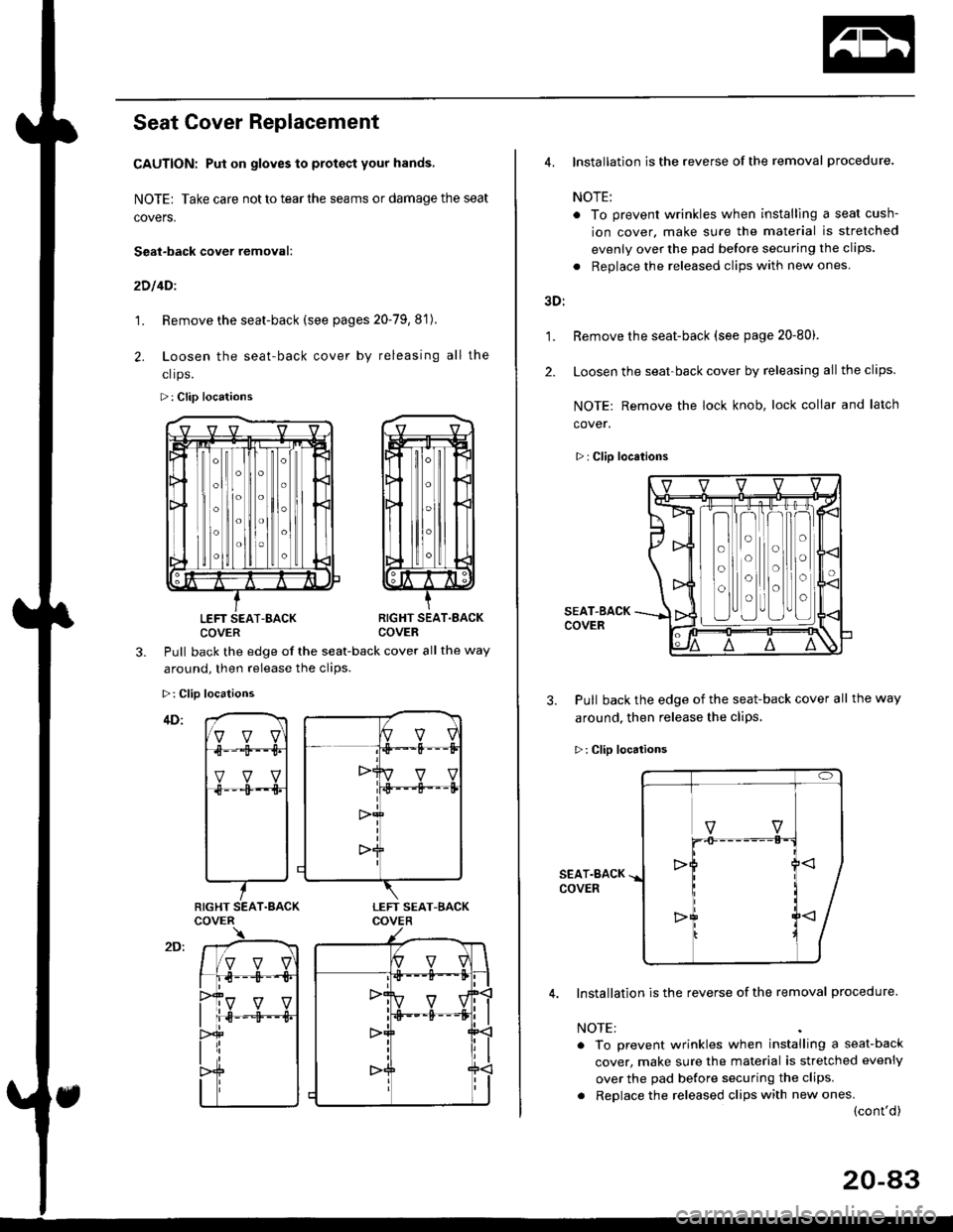
Seat Cover Replacement
CAUTION: Put on gloves to protact your hands,
NOTE| Take care not to tear the seams or damage the seat
covers.
Seat-back cover removal:
2D l4Dl
1. Remove the seat-back (see pages 20-79,8'1).
2. Loosen the seat-back cover by releasing all the
clrps.
>: Clip locations
LEFT SEAT-BACKCOVERRIGHT SEAT.EACKCOVER
3.Pull back the edge of the seat-back cover all the way
around. then release the clios.
>: Clip locations
RIGHT SEAT.BACK
1.
2.
4. Installation is the reverse of the removal procedure.
NOTE:
. To prevent wrinkles when installlng a seat cush-
ion cover. make sure the material is stretched
evenly over the pad before securing the clips.
. Replace the released clips with new ones
3D:
Remove the seat-back (see page 20-80).
Loosen the seat-back cover by releasing all the clips.
NOTE: Remove the lock knob, lock collar and latch
cover.
>: Clip locations
SEAT-BACKCOVER
3. Pull back the edge of the seat-back cover all the way
around, then release the cliPs.
>: Clip locations
SEAT.BACKCOVER
Installation is the reverse of the removal procedure.
NOTE:
. To prevent wrinkles when installing a seat-back
cover, make sure the material is stretched evenly
over the pad before securing the clips.
. Replace the released clips with new ones.(cont'd)
o
o
o
o
o
o
o
o
20-a3
Page 1314 of 2189

Rear Seat
Seat Cover Replacement (cont'dl
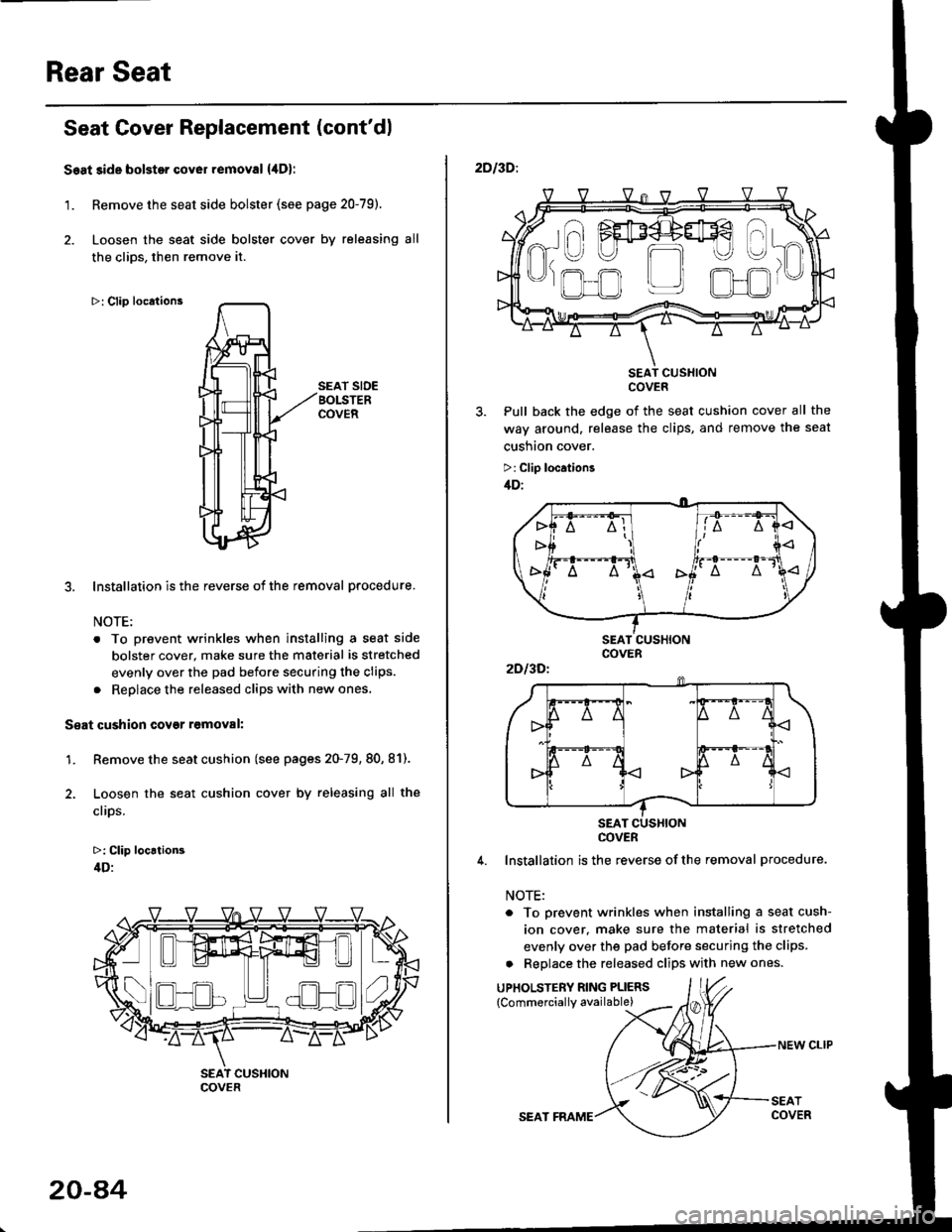
Seat side bolstor cover removal {,lDl
1. Remove the seat side bolster (see page 20-79).
2. Loosen the seat side bolster cover by releasing all
the clios, then remove it.
>: Clip locations
SEAT SIDEBOLSTERCOVER
3. Installation is the reverse of the removal procedure.
NOTE:
. To prevent wrinkles when installing a seat side
bolster cover, make sure the material is stretched
evenly over the pad before securing the clips.
. Reolace the released cliDs with new ones,
S€at cushion covgr r6moval:
1. Remove the seat cushion (see pages 20-79, 80, 81).
2. Loosen the seat cushion cover by releasing all the
clips.
>: Clip locrtion3
4D:
- -I ./al--lt___)l ) ( .)Ll!!l^t!!l 1",
COVER
20-a4
SEAT FRAME
NEW CLIP
2DI3D:.
SEAT CUSXIONCOVER
Pull back the edge of the seat cushion cover all the
way around, release the clips, and remove the seat
cusnton cover.
>: Clip location3
/tD:
4. Installation is the reverse ofthe removal procedure.
NOTE:
. To prevent wrinkles when installing a seat cush-
ion cover. make sure the material is stretched
evenly over the pad before securing the clips.
a Replace the released clips with new ones.
UPHOLSTERY RING PLIERS
{Commerciallv available)
a\
------)
t" I FEF4+#€
R-U U m
'J)
,.ofl r_r olJr
2Dl3Dl
COVER
Page 1322 of 2189

Seat Belts
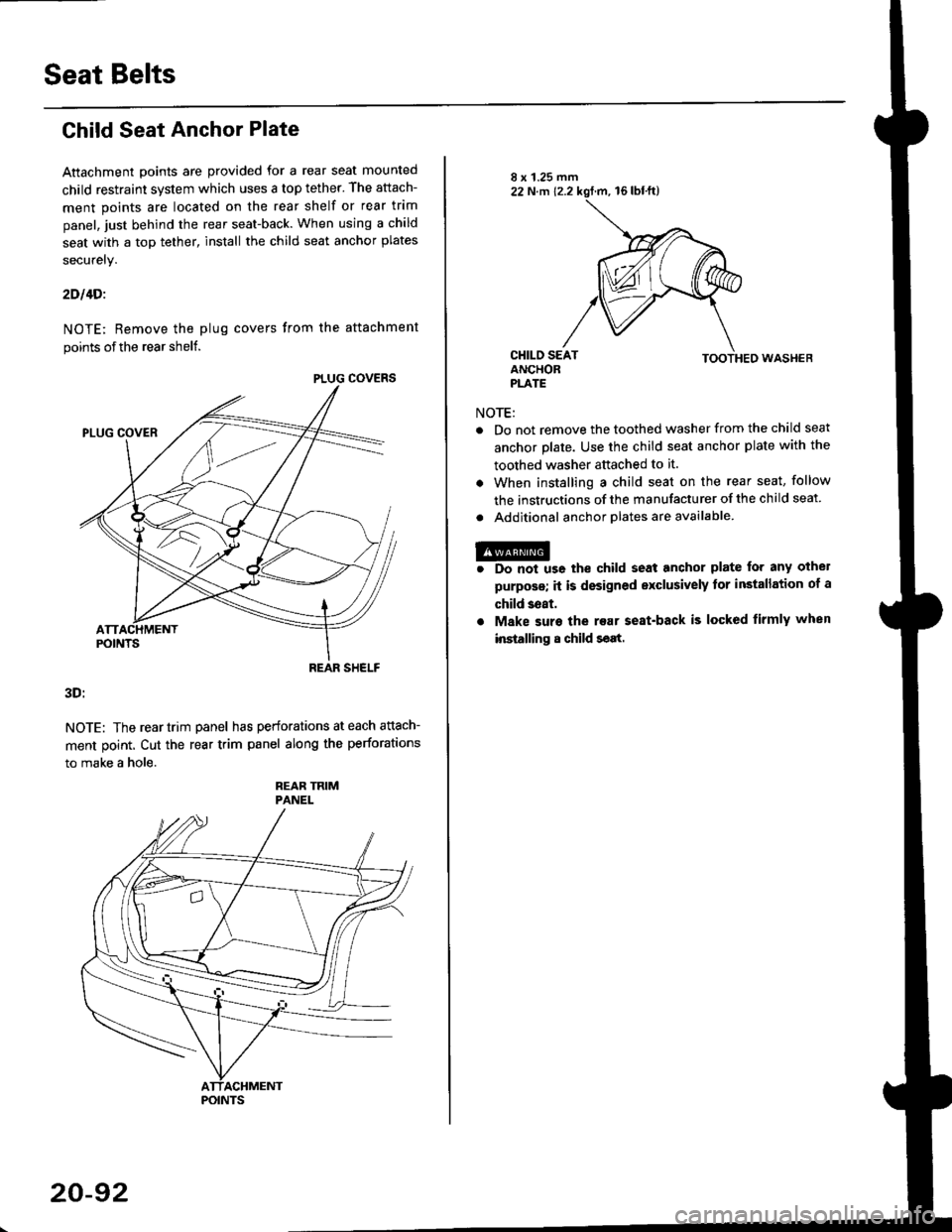
Child Seat Anchor Plate
Attachment points are provided for a rear seat mounted
child restraint system which uses a top tether. The attach-
ment points are located on the rear shelf or rear trim
panel, just behind the rear seat-back. When using a child
seat with a top tether, install the child seat anchor plates
securely.
2Dl4Di
NOTE; Remove the plug covers from the attachment
points of the rear shelf.
3D:
NOTE: The reartrim panel has perforations at each attach-
ment point. Cut the rear trim panel along the perforations
to make a hole.
REAR TRIMPANEL
PLUG COVERS
REAR SHELF
POINTS
20-92
NOTE:
TOOTHED WASHEB
Do not remove the toothed washer from the child seat
anchor plate. Use the child seat anchor plate with the
toothed washer attached to it.
When installing a child seat on the rear seat, follow
the instructions of the manufacturer of the child seat
Additional anchor olates are available.
@r Do not us6 the child seat anchor plate for any othel
purposs; it is designed exclusively tor installation of a
child 3eat.
. Make suro the rear seat-back is locked firmly when
installing 8 child seat.
Page 1324 of 2189
Front Bumper
Replacement
CAUTION: Put on glov$ to protect your hands.
NOTE:
. An assistant is helpful when removing the front bumper.
. Take care not to scratch the front bumDer and bodv.
FRONT BUMPERSIDE SNFFENER
lnstallation is the reverse of the removal orocedure.
NOTE:
. Make sure the front bumper engages the front
bumper side stiffener on each side securely.
. lf necessary, adjust the front bumper side stiffener
to obtain the proper gap.
>: golt, screw locationsa>,2B>,2>: Cliplocations, 7
iAerr:ore. A lm
L.'* fl'T;Ll'
o'n' -'
\€5>_ JIc>,4 ,D>,4
| -.6a 8 x 't.25 mm l,Rt o x 1.0 mm
l(Dl[m 22N.n'.t2.2kstnf'. j(Qll@ s.e N.m rr.o rsf.m,t'KJ) 16 tbf.ft, |. -ll 7.2 tbf.hJ
ABSORBER
FRONT EUMPERBEAM
FRONT BUMPERSIDE STIFFENER
FRONT BUMPER BEAM
:l
I ir
\
20-94
Page 1325 of 2189
Rear Bumper
Replacement
CAUTION: Put on gloveslo protect your hands.
NOTE:
. An assistant is helpful when removing the rear bumper.
. Take care not to scratch the rear bumper and body.
. 2D and 4D shown here;3D removal procedures are the same as 4D.
>: Screw, boll locationsA>,2 B>,4>: Clip locations, 7
Installation is the reverse of the removal Drocedure.
NOTE:
. lf necessary, replace any damaged clips.
. Make sure the rear bumper engages the side clip on each side securely.
n ,/_- Ert . -*E]s-
.A IVilIdfIT*ff
*,r/ \7
REAR BUMPER BEAM
REAR BUMPER
20-95